


 Loading...
Agilent U2751A USB
Modular Switch Matrix
User’s and Service Guide


 Agilent Technologies

Notices
® Agilent Technologies, Inc. , 2008, 2010
No part of this manual may be reproduced in any form or by any means (including electronic storage and retrieval or translation into a foreign language) without prior agreement and written consent from Agilent Technologies, Inc. as governed by United States and international copyright laws.
Manual Part Number
U2751-90011
Edition
Second Edition, April 12, 2010
Agilent Technologies, Inc.
3501 Stevens Creek Blvd.
Santa Clara, CA 95052 USA
Trademark Acknowledgements
Pentium is a U.S. registered trademark of Intel Corporation.
Microsoft, Visual Studio, Windows, and MS Windows are trademarks of Microsoft Corporation in the United States and/or other countries.
Warranty
The material contained in this document is provided “as is,” and is subject to being changed, without notice, in future editions. Further, to the maximum extent permitted by applicable law, Agilent disclaims all warranties, either express or implied, with regard to this manual and any information contained herein, including but not limited to the implied warranties of merchantability and fitness for a particular purpose. Agilent shall not be liable for errors or for incidental or consequential damages in connection with the furnishing, use, or performance of this document or of any information contained herein. Should Agilent and the user have a separate written agreement with warranty terms covering the material in this document that conflict with these terms, the warranty terms in the separate agreement shall control.
Technology Licenses
The hardware and/or software described in this document are furnished under a license and may be used or copied only in accordance with the terms of such license.
Restricted Rights Legend
U.S. Government Restricted Rights. Software and technical data rights granted to the federal government include only those rights customarily provided to end user customers. Agilent provides this customary commercial license in Software and technical data pursuant to FAR 12.211 (Technical Data) and 12.212 (Computer Software) and, for the Department of Defense, DFARS 252.227-7015 (Technical Data - Commercial Items) and DFARS 227.7202-3 (Rights in Commercial Computer Software or Computer Software Documentation).
Safety Notices
CAUTION
A CAUTION notice denotes a hazard. It calls attention to an operating procedure, practice, or the like that, if not correctly performed or adhered to, could result in damage to the product or loss of important data. Do not proceed beyond a CAUTION notice until the indicated conditions are fully understood and met.
WARNING
A WARNING notice denotes a hazard. It calls attention to an operating procedure, practice, or the like that, if not correctly performed or adhered to, could result in personal injury or death. Do not proceed beyond a WARNING notice until the indicated conditions are fully understood and met.
II |
U2751A User’s and Service Guide |
Safety Symbols
The following symbols on the instrument and in the documentation indicate precautions which must be taken to maintain safe operation of the instrument.
|
Direct current (DC) |
|
Off (supply) |
|
|
|
|
|
Alternating current (AC) |
|
On (supply) |
|
|
|
|
|
Both direct and alternating current |
|
Caution, risk of electric shock |
|
|
|
|
|
Three-phase alternating current |
|
Caution, risk of danger (refer to this |
|
|
|
manual for specific Warning or Caution |
|
|
|
information) |
|
|
|
|
|
Earth (ground) terminal |
|
Caution, hot surface |
|
|
|
|
|
Protective conductor terminal |
|
Out position of a bi-stable push control |
|
|
|
|
|
Frame or chassis terminal |
|
In position of a bi-stable push control |
|
|
|
|
|
Equipotentiality |
CAT I |
Measurements performed on circuits |
|
|
|
not directly connected to MAINS |
|
|
|
|
|
Equipment protected throughout by |
|
|
|
double insulation or reinforced |
|
|
|
insulation |
|
|
|
|
|
|
U2751A User’s and Service Guide |
III |

General Safety Information
WARNING
• Do not operate the device around explosive gas, vapor, or dust.
• Observe all markings on the device before establishing any connection.
• The device is under CAT I measurement category, do not connect the 25-pin connector to MAINS.
CAT I:
Maximum working voltage:
Standalone 35 Vrms
Modular (Used with U2781A) 180 Vrms
Maximum transient voltage: 300 Vrms
•Do not measure higher than the rated voltage (as marked on the device).
•Do not operate the device with the cover removed or loosened.
•Use only the power adapter provided by the manufacturer to avoid any unexpected hazards.
CAUTION |
• Electrostatic discharge (ESD) can cause damage to the components in |
|
the instrument and accessories. The cables or wires should be |
||
|
||
|
connected to the plug-in connectors first and covered with the wire |
|
|
casing prior to plugging it into the output connector to prevent ESD |
|
|
from occurring. |
|
|
• If the device is used in a manner not specified by the manufacturer, the |
|
|
device protection may be impaired. |
|
|
• Always use dry cloth to clean the device. Do not use ethyl alcohol or |
|
|
any other volatile liquid to clean the device. |
|
|
• Do not permit any blockage of the ventilation holes of the device. |
|
|
|
IV |
U2751A User’s and Service Guide |

Environmental Conditions
This instrument is designed for indoor use and in an area with low condensation. The table below shows the general environmental requirements for this instrument.
Environmental conditions |
Requirements |
|
|
Operating temperature |
0 °C to 50 °C |
Operating humidity |
20% to 85% RH non-condensing |
Storage temperature |
–20 °C to 70 °C |
Storage humidity |
5% to 90% RH non-condensing |
|
|
CAUTION
The U2751A USB modular switch matrix complies with the following safety and EMC requirements.
•IEC 61010-1:2001/EN61010-1:2001 (2nd Edition)
•Canada: CAN/CSA-C22.2 No. 61010-1-04
•USA: ANSI/UL 61010-1:2004
•IEC 61326-2002/EN 61326:1997+A1:1998+A2:2001+A3:2003
•Canada: ICES-001:2004
•Australia/New Zealand: AS/NZS CISPR11:2004
U2751A User’s and Service Guide |
V |
Regulatory Markings
|
The CE mark is a registered trademark |
|
The C-tick mark is a registered |
|
of the European Community. This CE |
|
trademark of the Spectrum |
|
mark shows that the product complies |
|
Management Agency of Australia. |
|
with all the relevant European Legal |
|
This signifies compliance with |
|
Directives. |
|
the Australia EMC Framework |
|
|
|
regulations under the terms of the |
|
|
|
Radio Communication Act of 1992. |
|
|
|
|
|
ICES/NMB-001 indicates that this |
|
This instrument complies with the |
|
ISM device complies with the |
|
WEEE Directive (2002/96/EC) |
|
Canadian ICES-001. |
|
marking requirement. This affixed |
|
Cet appareil ISM est confomre a la |
|
product label indicates that you must |
|
norme NMB-001 du Canada. |
|
not discard this electrical/electronic |
|
|
|
product in domestic household waste. |
|
|
|
|
|
The CSA mark is a registered |
|
|
|
trademark of the Canadian Standards |
|
|
|
Association. |
|
|
|
|
|
|
VI |
U2751A User’s and Service Guide |
Waste Electrical and Electronic Equipment (WEEE) Directive 2002/96/EC
This instrument complies with the WEEE Directive (2002/96/EC) marking requirement. This affixed product label indicates that you must not discard this electrical/electronic product in domestic household waste.
Product Category:
With reference to the equipment types in the WEEE directive Annex 1, this instrument is classified as a “Monitoring and Control Instrument” product.
The affixed product label is as shown below.
Do not dispose in domestic household waste
To return this unwanted instrument, contact your nearest Agilent
Technologies, or visit:
www.agilent.com/environment/product
for more information.
U2751A User’s and Service Guide |
VII |
In This Guide…
1Getting Started
This chapter provides an overview of the U2751A USB modular switch matrix, which includes the product outlook, product dimensions, and product layout. This chapter also contains instructions on how to install and configure the U2751A.
2Operation and Features
This chapter describes the operation and features that are offered by the U2751A, such as switch controls and relay usage monitoring.
3Characteristics and Specifications
This chapter contains the characteristics and specifications of the U2751A.
4Service Information
This chapter provides the guidelines for returning the U2751A to Agilent Technologies for servicing or for servicing it yourself. It also contains the list of replaceable parts.
VIII |
U2751A User’s and Service Guide |
U2751A User’s and Service Guide |
IX |

Declaration of Conformity (DoC)
The Declaration of Conformity (DoC) for this instrument is available on the Web site. You can search the DoC by its product model or description.
http://regulations.corporate.agilent.com/DoC/search.htm
NOTE
If you are unable to search for the respective DoC, please contact your local Agilent representative.
X |
U2751A User’s and Service Guide |
Contents
List of Figures |
XIII |
|
|
|
|
|
List of Tables |
XV |
|
|
|
|
|
1 Getting Started |
1 |
|
|
|
|
|
Introduction 2 |
|
|
|
|
|
|
Product at a Glance |
3 |
|
|
|
|
|
Product Outlook |
3 |
|
|
|
|
|
Product Dimensions |
5 |
|
|
|
|
|
Dimensions Without Bumpers |
5 |
|
||||
Dimensions With Bumpers |
6 |
|
|
|||
Standard Purchase Items |
7 |
|
|
|
||
Inspection and Maintenance |
8 |
|
|
|||
Initial Inspection |
8 |
|
|
|
|
|
Electrical Check |
8 |
|
|
|
|
|
General Maintenance |
8 |
|
|
|
||
Installation and Configuration |
9 |
|
|
|||
Installation |
9 |
|
|
|
|
|
A. Check Your System |
10 |
|
|
|
||
B. Install the IO Libraries Suite |
11 |
|
||||
C. Install the Module Driver |
12 |
|
|
|||
D. Install the Agilent Measurement Manager |
13 |
|||||
E. Connect the Module to Your PC |
15 |
|
||||
F. Verify Your Module Connection |
20 |
|
||||
G. Launch Your Agilent Measurement Manager |
21 |
|||||
U2751A DSub Connector |
|
23 |
|
|
||
U2751A User’s and Service Guide |
XI |
Contents
|
U2922A Terminal Block |
24 |
|
|||
|
U2922A Terminal Block Installation |
27 |
||||
|
55-Pin Backplane Connector Pin Configuration 29 |
|||||
|
Chassis Installation |
30 |
|
|
||
2 |
Operation and Features |
31 |
|
|||
|
Power Up |
32 |
|
|
|
|
|
Switch Control 33 |
|
|
|
|
|
|
Relay Cycle Counter |
36 |
|
|
|
|
|
System-Related Operation |
37 |
|
|||
|
Self-Test |
37 |
|
|
|
|
|
Error Conditions |
37 |
|
|
|
|
|
SCPI Commands for System-Related Tasks 38 |
|||||
3 |
Characteristics and Specifications |
39 |
||||
|
Product Characteristics |
40 |
|
|
||
|
Product Specifications |
41 |
|
|
||
4 |
Service Information |
43 |
|
|
||
|
Checking Defective Relay(s) |
44 |
|
|||
|
Replaceable Parts |
45 |
|
|
|
|
|
Disassembly Instructions |
46 |
|
|||
|
Reassembly Instructions |
48 |
|
|||
|
Contacting Agilent Technologies |
48 |
||||
XII |
U2751A User’s and Service Guide |
List of Figures
Figure 1-1. 25-pin male DSub connector 23
Figure 1-2. U2922A pin configuration |
24 |
|
Figure 1-3. U2922A outlook 25 |
|
|
Figure 1-4. U2922A dimensions 26 |
|
|
Figure 1-5. 55-pin backplane connector pin configuration 29 |
||
Figure 2-1. |
Switch matrix concept |
33 |
Figure 2-2. |
Panel view of the Agilent Measurement Manager 34 |
|
Figure 2-3. |
Panel view of the relay cycle counter 36 |
|
Figure 4-4. |
Defective relay(s) check |
44 |
U2751A User’s and Service Guide |
XIII |
XIV |
U2751A User’s and Service Guide |
List of Tables
Table 1-1. Pin assignments 23
Table 1-2. Synchronous Simultaneous Interface (SSI) connector pin description 29
Table 3-3. |
Electrical and mechanical specifications update per |
attached data sheet 41 |
|
Table 3-1. |
Electrical and mechanical specifications update per |
attached data sheet (continued) 42 |
|
Table 4-2. |
Part number and description of replaceable part 45 |
U2751A User’s and Service Guide |
XV |
XVI |
U2751A User’s and Service Guide |

U2751A USB Modular Switch Matrix
User’s and Service Guide
1
Getting Started
Introduction 2 |
|
|
|
|
|
|
Product at a Glance |
3 |
|
|
|
|
|
Product Outlook |
3 |
|
|
|
|
|
Product Dimensions |
5 |
|
|
|
|
|
Dimensions Without Bumpers |
5 |
|
|
|||
Dimensions With Bumpers |
6 |
|
|
|
||
Standard Purchase Items |
7 |
|
|
|
|
|
Inspection and Maintenance |
8 |
|
|
|
||
Initial Inspection |
8 |
|
|
|
|
|
Electrical Check |
8 |
|
|
|
|
|
General Maintenance |
8 |
|
|
|
|
|
Installation and Configuration |
9 |
|
|
|
||
Installation 9 |
|
|
|
|
|
|
A. Check Your System |
10 |
|
|
|
|
|
B. Install the IO Libraries Suite |
11 |
|
|
|||
C. Install the Module Driver |
12 |
|
|
|
||
D. Install the Agilent Measurement Manager |
13 |
|||||
E. Connect the Module to Your PC |
15 |
|
||||
F. Verify Your Module Connection |
20 |
|
||||
G. Launch Your Agilent Measurement Manager |
21 |
|||||
U2751A DSub Connector 23 |
|
|
|
|||
U2922A Terminal Block |
24 |
|
|
|
||
U2922A Terminal Block Installation |
27 |
|
||||
55-Pin Backplane Connector Pin Configuration |
29 |
|||||
Chassis Installation 30 |
|
|
|
|
||
Agilent Technologies |
1 |
1 Getting Started
Introduction
The U2751A USB modular switch matrix offers a high quality, low cost switching solution for automated test. It can operate as a standalone or modular unit when used with the U2781A USB modular instrument chassis.
The U2751A is a compact 4 8, two-wire modular switch matrix which is controlled remotely over a USB interface via the Agilent Measurement Manager software. The U2751A can also be programmed using the provided drivers or via SCPI commands.
The U2751A has the following features.
•32 two-wire cross-points organized in a 4 rows by 8 columns configuration
•any combination of rows and columns can be connected at a time. Multiple channels can be closed at the same time
•relay cycle counter
The U2751A offers you the most flexible connection path between your device under test (DUT) and your test equipment, allowing different instruments to be connected to multiple points on your DUT at the same time.
Using the Agilent Measurement Manager, you can instruct the matrix to make or break any of the 32 row-column intersections over the USB interface. More details will be covered in the Agilent Measurement Manager help file.
2 |
U2751A User’s and Service Guide |
Getting Started |
1 |
Product at a Glance
Product Outlook
Top View
Bumpers
U2751A User’s and Service Guide |
3 |

1 Getting Started
Front View
USB indicator
Power indicator
DSub connector
Rear View
55-pin backplane connector
USB inlet
Fastening hole for USB cable with locking mechanism
Power inlet
4 |
U2751A User’s and Service Guide |
Getting Started |
1 |
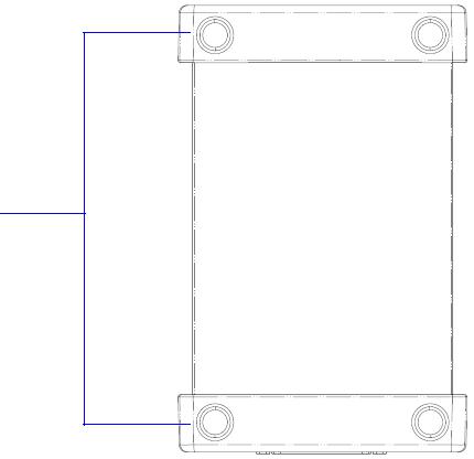
Product Dimensions
Dimensions Without Bumpers
Top View
105.00 mm
175.00 mm
Front View
25.00 mm
U2751A User’s and Service Guide |
5 |
Loading...