


How your 3499A/B/C Test System Benefits From Upgrading to the New 34980A Switch/Measure/Control System
Application Note
Add functionality, streamline your test programs, and reduce the physical test system size by upgrading from your 3499A/B/C to the new 34980A Multifunction Switch/Measure Unit.
This application note will describe differences and advantages of the new 34980A as compared to the 3499A/B/C. The 34980A Switch/Measure System masters switching, measurement, and control features by offering a superior selection of switch topologies and system control features. A state-of-the-art DMM has been integrated into the 34980A mainframe providing a wide variety of measure capability. The 34980A mainframe also includes standard PC connections and instrument control options for your ease of use.
Discover the detailed advantages of upgrading your test system using the 34980A in this document.
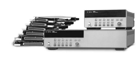
34980A Mainframe, plug-in modules and terminal cards
Measurements
One of the advantages of the new 34980A is its ability to make highly accurate test system measurements. The integration of a high-speed DMM into the mainframe enhances the 34980A switch and control system by providing voltage, current, temperature, frequency, and resistance measurements without using any of the mainframe’s available eight slots. The DMM conveniently generates measurement results in selectable engineering units. Eleven different types of measurements can be made and are listed on the page 2. The 34980A time-stamped measurement data can be stored or displayed and analyzed as the
measurements are acquired. The 34980A also has configurable High/Low limits on each channel that activate an alarm if the input signals are out of the set range. The 34980A’s integrated DMM saves you time and money by reducing the number of individual instruments required, and additional cabling for measurements and triggering. In comparison, the 3499A/B/C switch requires an external DMM or other measurement instrument as well as additional wiring to provide the same functionality.
List of 34980A Measurement
Capabilities
•Temperature measured with Thermocouples, RTDs and Thermistors
•DC and AC volts
•2- and 4-wire Resistance
•Frequency and Period
•DC and AC current
•4 alarms for High/Low or both limits for each channel
•Digital I/O
•Analog outputs (DAC)
The 34980A mainframe also includes four 2-wire internal analog buses. This is a differentiating 34980A feature and not included with the 3499A/B/C. The analog buses can be used to route measurements directly to the internal DMM or connect the mainframe modules to external instruments. The analog bus can be used to extend modules such as the matrix switch modules, or provide additional signal routing between modules.
Mainframes
The 34980A Multifunction Switch/Measure Unit consists of an eight-slot mainframe with an optional DMM. The DMM is mounted directly behind the front panel so it does not require any of the available eight module slots. A choice from 19 different modules can be plugged directly into the eight-slot mainframe.
In comparison, the 3499 Family has mainframes in three different sizes: A, B, and C that house five, two, and nine modules respectively. The 3499 Family offers a selection of 30 plug-in modules, 13 of which are the earlier generation HP 3488A Switch/Control Unit modules. Since some of the modules were designed for the 3488, and some modules specifically for the 3499, there is duplicate functionality between the modules.
As test systems and capability needs expand there is a call for a greater number of switch channels within one system. The 34980A switch modules are designed for high switching channel count. The 34980A eightslot mainframe fully loaded with 2-wire multiplexer modules houses a total switch channel count of 560. The 3499C nine-slot mainframe fully loaded with 2- wire multiplexer modules houses a total of 360 switch channels. For a quick summary of the maximum switch channel count for the switch systems mainframes, see Table 1.
|
Mainframe |
Mainframe Size |
Number of Module Slots |
Maximum Number |
|
|
|
|
|
of Channels (2-wire) |
|
|
34980A |
Full Rack, 3U |
8 |
560 |
|
|
3499B |
Rack, 2U |
2 |
80 |
|
|
3499A |
Half Rack, 2U |
5 |
200 |
|
|
3499C |
Full Rack, 5U |
9 (electrical)/ |
360 |
|
|
|
|
14 (physical) |
|
|
|
|
|
|
|
|
Table 1. Max 2-wire Mux channel count per Mainframe
2
Modules
The 34980A implements a superior selection of switch topologies. The 34980A switch topologies are similar to 3499A/B/C switch modules and include multiplexers, matrixes, high-power, general purpose, and RF/microwave switches. However, the 34980A modules have utilized the newest switch technology which enables a higher density of channels per module, and the ability to achieve the faster scan rates with the integrated DMM. The 34980A offers other functionality used in test systems and includes digital I/O, a counter/totalizer and D/A converters. New 34980A functions include a FET
multiplexer switch module, a counter/timer and digital I/O with pattern generator/detector along with digital I/O and D/A converters. The 34980A RF and microwave switch drivers offer functionality for a broader range of RF/microwave switches being used by customers today.
The 3499A/B/C does provide a selection of optics switching which is not available with the 34980A. Table 2 shows the 34980A and 3499A/B/C system modules organized by switch and/or measurement type. It is easy to compare and upgrade from the 3499A/B/C switch modules to the new 34980A switch modules as well as add new switch, measurement and control capabilities.
Benefits of the new 34980A modules vs 3499A/B/C modules
•Increased channel count per module with the same switch reliability
•Increased drivability for various RF/uWave switches
•High Speed FET multiplexer
•Reed Matrix switch
•Switch/attenuator driver
•Counter/Timer
•High Speed Digital I/O with memory
•Analog output with waveform capabilities
•Breadboard module with +5V, +12V
With so many different types of switch modules to choose from, you can easily identify the modules from Table 2 that provide the best solution to meet your test application needs. For detailed module specifications, please refer to the product data sheets available at these web locations: http://www.agilent.com/find/34980A and http://www.agilent.com/find/3499
3499A/B Mainframe and plug-in modules
3

Table 2. Direct comparison of 34980A and 3499 modules |
|
|
|
|
||||
|
|
|
|
|
|
|
|
|
|
Module Type |
34980A |
|
3499A/B/C |
||||
|
Multiplexer |
34921A |
40 Ch armature 300V 1A |
N2260A 40 Ch armature 200V 1A |
|
|||
|
|
34922A |
70 Ch armature 300V 1A |
N2266A 40 Ch reed 200V .5A |
||||
|
|
34923A |
40 Ch reed 200V .5A |
N2270A 10 Ch 1000V 1A |
||||
|
|
34924A |
70 Ch reed 80V .5 |
44470A |
10 Ch armature 250V 2A |
|||
|
|
34925A |
40 Ch FET +/-80V .5A |
44470D |
20 Ch armature 250V 2A |
|
||
|
General Purpose |
34937A |
28 Ch, 1A and 4 Ch, 5A |
N2261A 40 Ch |
||||
|
|
34938A |
20 Ch, 5A |
N2267A 8 Ch, 8A |
||||
|
|
|
|
|
44471A |
10 Ch |
||
|
|
|
|
|
44471D |
20 Ch |
||
|
|
|
|
|
44477A |
7 Ch SPDT (Form C) |
||
|
Matrix |
34931A Dual 4x8 armature 300V 1A |
N2262A 4x8 armature 200V 1A |
|
||||
|
|
34932A Dual 4x16 armature300V 1A |
44473A |
4x4 armature 250V 2A |
||||
|
|
34933A Dual 4x8 reed 80V .5A |
|
|
|
|
||
|
Digital I/O |
See multifunction 34950A, 34952A |
N2263A 32-bit TTL |
|
||||
|
|
|
|
|
44474A |
16-bit TTL |
||
|
Multifunction |
34952A |
32-bit Digital I/O with 2 Ch |
N2264A 12 GP, 3 GP 5A, 16-bit Dig I/O |
|
|||
|
|
|
DAC and Counter/Timer |
N2265A 4x4 matrix, 16-bit Dig I/O |
||||
|
|
34950A |
64-bit Digital I/O with Pattern |
N2269A 2 DAC, 16-bit Dig I/O |
||||
|
|
|
Generator/Detector |
|
|
|
|
|
|
Fiber-Optic Multiplexer |
|
|
|
N2280A Quad 1x2 |
|||
|
|
|
|
|
N2281A Dual 1x4 |
|||
|
|
|
|
|
N2282A Single 1x8 |
|||
|
RF & Microwave |
34941A Quad 1x4 RF 1.5G 50Ω, SMA |
N2268A Dual 1x4 3.5G 50Ω |
|
||||
|
|
34946A |
4G/20G 50Ω, 2 SPDT SMA |
N2272A Single 1x9 1.0G 50Ω |
||||
|
|
|
(N1810TL) |
N2276A Dual 1x6 20G 50Ω |
||||
|
|
34947A |
4G/20G 50Ω, 3 SPDT, SMA |
(87106B/4B) |
||||
|
|
|
(N1810UL) |
44472A |
Dual 1x4 300M 50Ω |
|||
|
|
|
|
|
44478A Dual 1x4 1.3G 50Ω |
|||
|
|
|
|
|
44476A |
Triple 1x2 18G 50Ω |
||
|
|
|
|
|
(8762B) |
|||
|
|
|
34942A Quad 1x4 RF 1.5G 75Ω, mSMB |
44478B Dual 1x4 1.3G 75Ω |
|
|||
|
|
34945A uwave Switch/Attn Driver |
N2276B Relay driver (2 switches) |
|||||
|
|
32 SPDT or 8 attenuators |
Choose from switches; |
|||||
|
|
The following µwave switches and |
87104A/B/C |
|||||
|
|
attenuators are supported with |
87106A/B/C |
|||||
|
|
the distribution1 boards; |
also drive two external attenuators |
|||||
|
|
|
N181x series SPDT switches |
84904/6/7/K/L |
||||
|
|
|
876X series SPDT switches |
|
|
|
|
|
|
|
|
87104x/106x multi-port switches |
44476B Relay driver (2 switches) |
||||
|
|
|
87606x series matrix switches |
Choose from switches; |
||||
|
|
|
8722x transfer switches |
8762A/B/C/F |
||||
|
|
|
849x series attenuators |
8763B/C |
||||
|
|
|
8490x series attenuators |
8764B/C |
||||
|
|
|
Generic screw terminal connections |
|
|
|
|
|
|
|
|
Third-party switches (screw terminals) |
|
|
|
|
|
|
DAC |
34951A Quad 16-bit D/A Converter |
See multifunction |
|||||
|
Breadboard |
34959A |
+12 V, +5 V |
44475A |
5.5 |
|
|
|
|
|
|
|
|
|
|
|
|
User Interface
The 34980A offers the most modern instrument I/O options for interfacing a controller PC with the switch system: GPIB, USB and LAN. All three Input/Output interface connections come standard with the 34980A mainframe. If you choose to modify or upgrade your test system I/O, the 34980A is system ready.
You can also easily control the 34980A without connecting to a PC by pressing the front-panel buttons, an advantage when first setting up or troubleshooting a system.
Upgrading your test system from using the 3499A/B/C GPIB to the 34980A GPIB, or newer USB or LAN is quick and easy. If you have used I/O Config from the Agilent I/O Libraries to set your GPIB instrument connection, you would use the same I/O Config to set up your LAN or “TCPIP” instrument connection. Retrieve the LAN, TCPIP address from your instrument and enter it into I/O Config. When you address your instrument in a program, it will look similar to; TCPIP0::9::INSTR. For more information on
connecting to Agilent instruments you can access the Agilent Technologies USB/LAN/GPIB Interfaces Connectivity Guide at www.agilent.com/find/connectivity With LAN, the instrument can be located closer to the device under test without worrying about the distance to the PC. A USB to instrument connection is even easier. The computer automatically detects instruments that are USB ready. If you are currently using the 3499A/B/C RS232 interface, it is recommended to upgrade to the 34980A GPIB, USB or LAN interface to achieve optimal data transfer rates.
Instrument Control (Programming)
The 34980A and 3499A/B/C can both be controlled locally from the front panel, or by sending either instrument or driver commands from a PC for remote control. The 34980A’s instrument commands and drivers are based on modern standards such as SCPI (standard commands for programmable instruments) and IVI-C and IVI COM drivers. The SCPI instrument
similar to the 3499A/B/C’s but they are not interchangeable. A comparison of the commands is provided in appendix A. The 34980A's IVI-C and IVI-COM drivers are similar to Plug & Play drivers, the 3499A/B/C's Plug & Play driver for example, but include improvements. The IVI (Interchangeable Virtual Instruments) driver specification was built upon the Plug&Play driver specification but adds the capabilities provided by the Microsoft ActiveX technologies which simplify instrument interchangeability, and product performance. The 34980A also includes many new commands for the operation of the embedded DMM. A 34980A Web interface provides a new easy way to communicate via LAN with the instrument.
Table 3 shows a summary of the programming control options available for the 3499A/B/C and the 34980A. There is similarity between the instrument commands, however, the 34980A has evolved to use the most modern and widely accepted instrument command standards.
Table 3. Control Options for 3499A/B/C and 34980A |
|
|
||
|
|
|
|
|
|
|
3499A/B/C |
34980A |
|
|
Front Panel Buttons |
● |
● |
|
|
3488 Legacy Commands |
● |
|
|
|
SCPI Commands |
● |
● |
|
|
Plug & Play driver |
● |
|
|
|
IVI COM driver |
● |
● |
|
|
IVI-C driver |
|
● |
|
|
LabVIEW driver |
|
● |
|
|
Web Interface |
|
● |
|
|
|
|
|
|
5

Listed below are each of the many ways available to communicate and control the 34980A, the communication options and their description
Web Page Interface
The 34980A comes with a built-in detailed instrument web page that allows you to remotely connect and communicate with the mainframe and installed modules. You establish a LAN connection, either directly between the 34980A and PC, or from the 34980A to an existing Local Area Network. The instrument Web page resides on the 34980A and can be accessed using a standard web browser such as Netscape or Internet Explorer on a PC. Just type the IP address into the web browser. The web interface allows you to select any of the installed modules and view the current configuration, change settings, make measurements, and makes it easy to troubleshoot or debug the switch/measure system. The instrument web interface also allows you to check the current status of the instrument by viewing the error queue, calibration status and the accumulated module switch closures.
Web interface display for 34921A MUX Switch module
Web interface display of scanned measurements
6
 Loading...