


 Loading...
Agilent E2050 LAN/GPIB
Gateway Installation and
Configuration Guide
Manual Part Number: E2050-90003
Printed in U.S.A. E0701

Contents
E2050 LAN/GPIB Gateway User’s Guide
Front Matter............................................................................................... |
5 |
Warranty Information .................................................................... |
5 |
Contacting Agilent ......................................................................... |
6 |
Safety Considerations ................................................................... |
7 |
Radio and Television Interference ................................................ |
7 |
Declaration of Conformity .............................................................. |
9 |
1. Introduction ........................................................................................ |
11 |
How to Use This Guide................................................................ |
13 |
Guide Contents .................................................................... |
13 |
Related Software Documentation ......................................... |
14 |
E2050 Hardware Description ....................................................... |
15 |
E2050 LAN/GPIB Gateway Front Panel ............................... |
15 |
E2050 LAN/GPIB Gateway Rear Panel ............................... |
16 |
AC/DC Adapter and AC Power Cord .................................... |
17 |
Rack Mount Kit (Optional) .................................................... |
17 |
E2050 Software/Firmware Architecture ....................................... |
18 |
I/O Application Software Supported ..................................... |
18 |
Typical LAN Connections ..................................................... |
19 |
Software/Firmware Architecture Overview ........................... |
21 |
Using Application Software .................................................. |
22 |
2. Installation .......................................................................................... |
23 |
Hardware Requirements.............................................................. |
25 |
Software Requirements ............................................................... |
26 |
Installing the Hardware ................................................................ |
27 |
3. Configuration ..................................................................................... |
33 |
Setting Configuration Values ....................................................... |
35 |
Steps to Set Configuration Values ....................................... |
35 |
Configuration Values Descriptions ....................................... |
35 |
How Configuration Values are Used .................................... |
41 |
Configuration Methods................................................................. |
43 |
Configuration Methods Overview ......................................... |
43 |
Using Telnet Configuration Method (Windows) .................... |
45 |
Using Telnet Configuration Method (HP-UX) ....................... |
50 |
Using BOOTP Configuration Method (HP-UX) ..................... |
55 |
Using BOOTP with TFTP Configuration Method (HP-UX) ... |
58 |
Contents 3

4. Administration .................................................................................... |
63 |
Using the Telnet Utility.................................................................. |
65 |
Accessing the Telnet Utility ................................................... |
65 |
Exiting the Telnet Utility ........................................................ |
68 |
Telnet Commands ................................................................. |
68 |
Querying the Gateway.................................................................. |
70 |
Querying the Current Configuration ...................................... |
70 |
Querying the Firmware Revision ........................................... |
70 |
Querying the Configuration Method ...................................... |
71 |
Querying Gateway/Client Connections ................................. |
71 |
Configuring the Gateway.............................................................. |
75 |
Setting Default Configuration Values .................................... |
75 |
Changing the Configuration Method ..................................... |
75 |
Using the Gateway’s syslog File ........................................... |
77 |
Terminating Client Connections ............................................ |
79 |
5. Troubleshooting ................................................................................. |
81 |
Gateway Failure Messages .......................................................... |
83 |
SICL Error Codes and Messages ......................................... |
83 |
syslog File Messages ............................................................ |
84 |
Troubleshooting Network Configuration ....................................... |
85 |
Verifying Network Connections ............................................. |
85 |
Troubleshooting Network Configurations .............................. |
86 |
Troubleshooting Gateway Configuration ...................................... |
88 |
Verifying Gateway Configuration .......................................... |
88 |
Setting Default Configuration ................................................ |
88 |
Verifying the Configuration Method ....................................... |
89 |
Changing the Configuration Method ..................................... |
91 |
Troubleshooting Telnet Configuration ................................... |
92 |
Troubleshooting BOOTP Configuration ................................ |
92 |
Troubleshooting BOOTP with TFTP Configuration ............... |
93 |
Troubleshooting Client Connections............................................. |
94 |
Client Connection Problems ................................................. |
94 |
Client Run-time Errors .......................................................... |
96 |
A. Specifications ................................................................................... |
99 |
Glossary ................................................................................................ |
103 |
Index ...................................................................................................... |
107 |
Contents 4

Notice
The information contained in this document is subject to change without notice.
Agilent Technologies shall not be liable for any errors contained in this document. Agilent Technologies makes no warranties of any kind with regard to this document, whether express or implied. Agilent Technologies specifically disclaims the implied warranties of merchantability and fitness for a particular purpose. Agilent Technologies shall not be liable for any direct, indirect, special, incidental, or consequential damages, whether based on contract, tort, or any other legal theory, in connection with the furnishing of this document or the use of the information in this document.
Warranty Information
A copy of the specific warranty terms applicable to your Agilent Technologies product and replacement parts can be obtained from Agilent Technologies, Inc.
U.S. Government Restricted Rights
The Software and Documentation have been developed entirely at private expense. They are delivered and licensed as "commercial computer software" as defined in DFARS 252.2277013 (Oct 1988), DFARS 252.2117015 (May 1991) or DFARS 252.227-7014 (Jun 1995), as a "commercial item" as defined in FAR 2.101(a), or as "Restricted computer software" as defined in FAR 52.227-19 (Jun 1987) (or any equivalent agency regulation or contract clause), whichever is applicable. You have only those rights provided for such Software and Documentation by the applicable FAR or DFARS clause or the Agilent standard software agreement for the product involved.
5

Trademark Information
Microsoft®, Windows ® 95, Windows ® 98, Windows ® Me,
Windows ® 2000, and Windows NT® are U.S. registered trademarks of Microsoft Corporation. All other brand and product names are trademarks or registered trademarks of their respective companies.
This software and documentation are based in part on the Fourth Berkeley Software Distribution under license from The Regents of the University of California. We acknowledge the Regents of the University of California for their role in the development of this software and documentation.
Printing History
Edition 1 - February 1995
Edition 2 - November 1995
Edition 3 - May 1996
Edition 4 - July 2001
Copyright Information
Agilent Technologies E2050 LAN/GPIB Gateway
Installation and Configuration Guide
Edition 4
Portions of the TCP/IP software are copyright Phil Karn, KA9Q. Copyright © 1984, 1985, 1986, 1987, 1988 Sun Microsystems, Inc. Copyright © 1995-1996, 2001 Agilent Technologies, Inc.
All rights reserved.
Contacting Agilent
nIn the USA and Canada, you can reach Agilent Technologies at these telephone numbers:
USA: 1-800-452-4844
Canada: 1-877-894-4414
nOutside the USA and Canada, contact your country’s Agilent support organization. A list of contact information for other countries is available on the Agilent web site:
http://www.agilent.com/find/assist
6

Safety Considerations
Product and Documentation Labels
A WARNING denotes a hazard that can cause injury or death. A CAUTION denotes a hazard that can damage equipment or cause data loss. Do not proceed beyond a WARNING or CAUTION notice until you understand the hazardous conditions and have taken appropriate steps.
Grounding
The power module (Agilent 0950-2546 AC/DC Adapter) is a safety class I product and has a protective earthing terminal. There must be an uninterruptible safety earth ground from the main power source to the product’s input wiring terminals, power cord, or power cord set. Whenever it is likely that the protection has been impaired, disconnect the power cord until the ground has been restored.
Servicing
There are no user-serviceable parts inside the E2050 LAN/GPIB Gateway or its power module (AC/DC Adapter). Any servicing, adjustment, maintenance, or repair must be performed by service-trained personnel only. The power module does not have a power switch. The power cord is intended to serve as the disconnect device. Make sure the power module is installed near a wall outlet and is easily accessible.
Radio and Television Interference
This device has been verified to comply with FCC Rules Part 15. Operation is subject to these two conditions: (1) this device may not cause radio interference, and (2) this device must accept any interference received (including interference that may cause undesired operation).
This equipment generates and uses radio frequency energy. If not installed and used in accordance with this manual, it can cause interference to radio and television communications. The rules with which it must comply afford reasonable protection against such interference when it is used in most locations.
However, there can be no guarantee that such interference will not occur in a particular installation. If you think your device is causing interference, turn off the system. If the radio or television reception does not improve, your device is probably not causing the interference.
7

If your device does cause interference to radio and television reception, you are encouraged to try to correct the interference by one or more of the following measures:
nRelocate the radio or TV antenna.
nMove the device away from the radio or television.
nPlug the device into a different electrical outlet, so that the device and the radio or television are on separate electrical circuits.
nMake sure you use only shielded cables to connect peripherals to your device.
nConsult your dealer, Agilent Technologies, or an experienced radio/ television technician for other suggestions.
nOrder the FCC booklet How to Identify and Resolve Radio-TV Interference Problems from the U.S. Government Printing Office, Washington, D.C. 20402. The stock number of this booklet is 004-000-00345-4.
8

|
|
DECLARATION OF CONFORMITY |
|
|
|
According to ISO/IEC Guide 22 and CEN/CENELEC EN 45014 |
|
|
|
|
|
Manufacturer’s Name: |
|
Agilent Technologies, Incorporated |
|
Manufacturer’s Address: |
|
815 - 14th St. SW |
|
|
|
Loveland, Colorado 80537 |
|
|
|
USA |
|
Declares, that the product |
|||
Product Name: |
LAN/GPIB Gateway |
||
Model Number: |
E2050B |
||
Product Options: |
This declaration covers all options of the above product(s). |
||
Conforms with the following European Directives:
The product herewith complies with the requirements of the Low Voltage Directive 73/23/EEC and the EMC Directive 89/336/EEC (including 93/68/EEC) and carries the CE Marking accordingly.
Conforms with the following product standards: |
|
|
EMC |
Standard |
Limit |
|
IEC 61326-1:1997+A1:1998 / EN 61326-1:1997+A1:1998 |
|
|
CISPR 11:1990 / EN 55011:1991 |
Group 1 Class A |
|
IEC 61000-4-2:1995+A1:1998 / EN 61000-4-2:1995 |
4kV CD, 8kV AD |
|
IEC 61000-4-3:1995 / EN 61000-4-3:1995 |
3 V/m, 80-1000 MHz |
|
IEC 61000-4-4:1995 / EN 61000-4-4:1995 |
0.5kV signal lines, 1kV power lines |
|
IEC 61000-4-5:1995 / EN 61000-4-5:1995 |
0.5 kV line-line, 1 kV line-ground |
|
IEC 61000-4-6:1996 / EN 61000-4-6:1996 |
3V, 0.15-80 MHz |
|
IEC 61000-4-11:1994 / EN 61000-4-11:1994 |
Dips: 30% 10ms; 60% 100ms |
|
Canada: ICES-001:1998 |
Interrupt > 95%@5000ms |
|
|
|
|
Australia/New Zealand: AS/NZS 2064.1 |
|
|
The product was tested in a typical configuration with Agilent Technologies test systems |
|
Safety |
IEC 61010-1:1990+A1:1992+A2:1995 / EN 61010-1:1993+A2:1995 |
|
|
Canada: CSA C22.2 No. 1010.1:1992 |
|
|
UL 3111-1: 1994 |
|
21 June 2001 |
|
|
|
|
|
Date |
|
Ray Corson |
|
|
Product Regulations Program Manager |
For further information, please contact your local Agilent Technologies sales office, agent or distributor. Authorized EU-representative: Agilent Technologies Deutschland GmbH, Herrenberger Straße 130, D 71034 Böblingen, Germany
9

10
1
Introduction
11

Introduction
This Agilent E2050 LAN/GPIB Gateway Installation and Configuration Guide gives guidelines to install and configure the E2050 LAN/GPIB Gateway (Gateway) for use with supported, network-equipped computer systems. You can also use this guide to administer the Gateway on your network and to troubleshoot installation or configuration problems. This chapter includes:
nHow to Use This Guide
nE2050 Hardware Description
nE2050 Software/Firmware Architecture
12 |
Chapter 1 |

Introduction
How to Use This Guide
How to Use This Guide
The information in this guide assumes you are a Network Administrator who installs, configures, and maintains a local area network (LAN), including network-related hardware like the E2050 LAN/GPIB Gateway.
If you use a Series 700 HP-UX workstation with the Gateway, you must also have super-user (root) privileges on the HP-UX system. If you use a Windows NT PC with the Gateway, you must also have system administrator privileges on the Windows NT PC.
Guide Contents
|
Chapter |
Description |
|
|
|
Chapter 1 - Overview |
Provides an overview of the E2050 LAN/GPIB Gateway. |
|
|
|
|
Chapter 2 - Installation |
Shows how to install the Gateway on LAN and GPIB. |
|
|
|
|
Chapter 3 - Configuration |
Shows how to configure the Gateway on your network. |
|
|
|
|
Chapter 4 |
- Administration |
Shows how to maintain the Gateway on the network. |
|
|
|
Chapter 5 |
- Troubleshooting |
Provides ways to fix problems with the Gateway. |
|
|
|
Appendix A - Specifications |
Provides specifications for the Gateway. |
|
|
|
|
Glossary |
|
Technical terms used in this guide. |
|
|
|
Chapter 1 |
13 |

Introduction
How to Use This Guide
|
Related Software Documentation |
|
Suggested software manuals you can use for E2050 LAN/GPIB Gateway |
|
operation with the listed I/O application software products follow. The E2050 |
|
Gateway supports all I/O application operations by these software products |
|
except for parallel polling, SICL commander sessions, and asynchronous |
|
aborting. |
|
|
Product |
Related Documentation |
|
|
VISA |
To use the LAN/GPIB Gateway, you must configure the LAN Client software |
|
provided with VISA. See the Agilent I/O Libraries Installation and |
|
Configuration Guide for configuration procedures. To develop and use VISA |
|
I/O applications for the Gateway, see Agilent VISA User’s Guide. |
|
|
SICL |
To use the LAN/GPIB Gateway, you must configure the LAN Client software |
|
provided with SICL. See the Agilent I/O Libraries Installation and |
|
Configuration Guide for configuration procedures. |
|
To develop and use SICL I/O applications for the Gateway in Windows, see |
|
the Agilent SICL User’s Guide for Windows. To develop and use SICL I/O |
|
applications for the Gateway in HP-UX, see the Agilent SICL User’s Guide |
|
for HP-UX. |
|
|
VEE |
To use the LAN/GPIB Gateway, see the VEE User’s Manual for configuration |
|
procedures. To develop and use VEE I/O applications for the Gateway, see |
|
the VEE User’s Manual. |
|
|
BASIC/ |
Version 8.x |
UX 700 |
To use the LAN/GPIB Gateway, you must configure the SICL LAN Client |
|
software provided with BASIC/UX 700 Version 8.x. See the Installing and |
|
Using BASIC/UX 8.x manual for configuration procedures. To develop and |
|
use BASIC/UX 700 Version 8.x I/O applications for the Gateway, see the |
|
BASIC Interface Reference manual. |
|
Version 7.1 |
|
To use the LAN/GPIB Gateway, you must configure the SICL LAN Client |
|
software provided with BASIC/UX 700 Version 7.1. See the Installing and |
|
Maintaining HP BASIC/UX manual for configuration procedures. To develop |
|
and use BASIC/UX 700 Version 7.1 I/O applications for the Gateway, see the |
|
BASIC Interface Reference manual. |
|
|
14 |
Chapter 1 |

Introduction
E2050 Hardware Description
E2050 Hardware Description
In addition to this guide, the E2050 product package consists of:
nE2050 LAN/GPIB Gateway Front Panel
nE2050 LAN/GPIB Gateway Rear Panel
nAC/DC Adapter and Standard AC Power Cord
nRack Mount Kit (Optional)
E2050 LAN/GPIB Gateway Front Panel
As shown in the following figure, the front panel of the Gateway contains 8 light-emitting diodes (LEDs) that indicate the status of the Gateway.
E2050 |
LAN |
GPIB |
LAN/GPIB Gateway |
|
|
Power Fail |
Conn Tx Rx |
Talk Listen SRQ |
|
|
|
|
|
|
|
|
|
|
|
|
|
|
|
|
|
|
|
|
|
E2050 LAN/GPIB Gateway Front Panel |
||||||||||||||||
|
|
|
|
|
|
|
|
|
|
|
|
|
|
|
|
|
|
|
LED |
Color |
|
Meaning When Illuminated |
|||||||||||||||
|
|
|
|
|
|
|
|
|
|
|
|
|
|
|
|
|
|
|
Power |
Green |
Power is applied to the Gateway. |
||||||||||||||||
|
|
|
|
|
|
|
|
|
|
|
|
|
|
|
|
|
|
|
Fault |
Red |
Diagnostic failure of the hardware. This LED will normally be off. |
||||||||||||||||
|
|
|
|
|
|
|
|
|
|
|
|
|
|
|
|
|
|
|
LAN Conn |
Yellow |
A TCP/IP port is open (Telnet or a LAN connection). Flashes at a |
||||||||||||||||
|
|
fast rate for BOOTP or a BOOTP with TFTP configuration. Flashes |
||||||||||||||||
|
|
at a slow rate when the default IP address (192.0.0.192) is used |
||||||||||||||||
|
|
(after the Config Preset button is pressed). |
||||||||||||||||
|
|
|
|
|
|
|
|
|
|
|
|
|
|
|
|
|
|
|
LAN Tx |
Yellow |
Flashes at 10 Hz rate when transmitting packets on the LAN. |
||||||||||||||||
|
|
|
|
|
|
|
|
|
|
|
|
|
|
|
|
|
|
|
LAN Rx |
Yellow |
Flashes at 10 Hz rate when receiving packets from the LAN. |
||||||||||||||||
|
|
|
|
|
|
|
|
|
|
|
|
|
|
|
|
|
|
|
GPIB Talk |
Yellow |
The Gateway is configured to TALK on the GPIB bus. |
||||||||||||||||
|
|
|
|
|
|
|
|
|
|
|
|
|
|
|
|
|
|
|
GPIB Listen |
Yellow |
The Gateway is configured to LISTEN on the GPIB bus. |
||||||||||||||||
|
|
|
|
|
|
|
|
|
|
|
|
|
|
|
|
|
|
|
GPIB SRQ |
Yellow |
The GPIB SRQ line is asserted. |
||||||||||||||||
|
|
|
|
|
|
|
|
|
|
|
|
|
|
|
|
|
|
|
Chapter 1 |
15 |

Introduction
E2050 Hardware Description
E2050 LAN/GPIB Gateway Rear Panel
This figure shows the back panel features of the Gateway. Note that the RS-232 interface is NOT supported for I/O application use..
RJ-45 connector for 10 Base-T, unshielded twisted-pair cable (Ethertwist LAN)
BNC connector for
10 Base2, thin coaxial cable (ThinLAN)
RS-232 connector (the RS-232 interface is not supported for I/O application use)
GPIB Connector |
Config Preset button for resetting |
|
the Gateway to its factory-set |
|
default configuration values |
Power input for the DC cable from the AC/DC Adapter (power module)
E2050 LAN/GPIB Gateway Rear Panel
NOTE
Converters are available that provide an Attachment Unit Interface (AUI) connection (10 Base-T to DB15 AUI port) for ThickLAN or fiber optic networks (for Ethernet/IEEE 802.3 protocol).
You will need to purchase both a converter and a Medium Attachment Unit (MAU) to use the E2050 LAN/GPIB Gateway with ThickLAN or a fiber optic network. Contact Agilent Technologies for information on these and other networking products.
16 |
Chapter 1 |
Introduction
E2050 Hardware Description
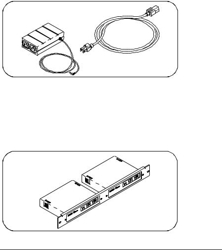
AC/DC Adapter and AC Power Cord
As shown in the following figure, the power module (AC/DC Adapter) (Agilent part number 0950-2546) provides 5 Vdc power to the Gateway. The 4-foot, DC cable attached to the power module connects to the power input on the back panel of the Gateway. The universal AC outlets on the power module can automatically accept and adapt to 100-240 Vac power.
The separate AC power cord connects to the AC IN outlet on the power module and to a power outlet (wall outlet), thus providing power to the power module and Gateway. You should have received the appropriate AC power cord for your country.
AC/DC Adapter and Standard AC Power Cord
Rack Mount Kit (Optional)
As shown in the following figure, this optionally purchased E2051 Rack Mount Kit allows you to mount up to two LAN/GPIB Gateways in a rack frame. A light-duty, fixed shelf is also required. It is recommended you use an Agilent E3666 Plain Shelf with this rack mount kit.
Rack Mount Kit (Optional)
Chapter 1 |
17 |

Introduction
E2050 Software/Firmware Architecture
E2050 Software/Firmware Architecture
This section describes E2050 software/firmware architecture, including:
nI/O Application Software Supported
nTypical LAN Connections
nSoftware/Firmware Overview
nUsing Applications Software
I/O Application Software Supported
The E2050 LAN/GPIB Gateway supports these I/O application software products. The Gateway supports all I/O application operations provided by these software products except for parallel polling, SICL commander sessions, and asynchronous aborting.
nAgilent Virtual Instrument Software Architecture (VISA) on HP-UX or on Microsoft Windows 95, Windows 98, Windows 2000, Windows Me, or Windows NT (for WIN32 applications only), as applicable.
nAgilent Standard Instrument Control Library (SICL) on HP-UX or on Microsoft Windows 95, Windows 98, Windows 2000, Windows Me, or Windows NT (for WIN32 applications only).
nAgilent Visual Engineering Environment (VEE) on HP-UX or on Microsoft Windows 95, Windows 98, Windows 2000, Windows Me, or Windows NT (for WIN32 applications only).
nHP BASIC/UX 700 Version 7.1 or Version 8.x on HP-UX.
18 |
Chapter 1 |

Introduction
E2050 Software/Firmware Architecture
Typical LAN Connections
The E2050 LAN/GPIB Gateway combines hardware and firmware in a single box that provides a network gateway between network-equipped computer systems and GPIB based instruments. The Gateway enables users of I/O applications to obtain measurement data either locally or remotely from GPIB instrumentation. The following figure shows typical LAN connections for an E2050 Gateway.
Computer Systems
LAN
LAN
E2050
LAN/GPIB
Gateway
GPIB bus
GPIB Instruments
Typical LAN Connections
Chapter 1 |
19 |
Introduction
E2050 Software/Firmware Architecture
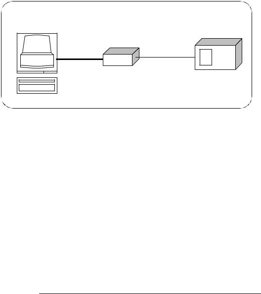
The Gateway connects the local area network (LAN) from the computer system to the GPIB bus. Network-equipped computer systems that are supported for use with the Gateway include Series 700 workstations and 32-bit PCs. Following the client/server model of computing, the computer system is the client, and the E2050 LAN/GPIB Gateway acts as the server.
Client System |
Server |
GPIB Instrument |
|
E2050 |
|
|
LAN |
GPIB bus |
Client - Server Configuration
Thus, I/O applications running on the computer system can transparently interface to GPIB-based instruments over the LAN. Since several computer systems can access the LAN/GPIB Gateway, groups of users can share access to the same GPIB instruments via the Gateway. In addition, existing I/O applications that are supported with the LAN/GPIB Gateway and are designed for GPIB can use the Gateway without modification beyond an address change.
The Gateway and its attached GPIB instruments can be placed anywhere on the network (rather than with a particular controller or server computer system). This includes networks which span different geographic locations, such as when networked computer systems are located at several different sites. Hence, GPIB instruments can be located where they are most convenient for I/O application users.
In addition, you can have more than one LAN/GPIB Gateway on a network, providing “clusters” of GPIB instrumentation at different locations. This further aids users in accessing the instrumentation they need for their specific I/O applications.
20 |
Chapter 1 |
Introduction
E2050 Software/Firmware Architecture
Software/Firmware Architecture Overview
Agilent SICL contains the LAN client software needed to access the LAN/GPIB Gateway. Thus, SICL is also provided with the VISA, VEE, and HP BASIC/UX 700 I/O application software products. To use any of these software products with the LAN/GPIB Gateway, you must also install and configure SICL on the client computer system.
Several of these software products support two different LAN networking protocols: the SICL LAN Protocol and the TCP/IP Instrument Protocol. Version A.01.00 or later of the LAN/GPIB Gateway supports the SICL LAN Protocol and VXI-11 (TCP/IP Instrument Protocol). To check your version of the Gateway (and the protocol(s) you can use with the Gateway depending on the software product you have), see Chapter 4.
As shown in the following figure, the client system contains the LAN client software provided with SICL as well as the TCP/IP LAN software needed to access the Gateway. The Gateway contains LAN server and TCP/IP LAN firmware so that it acts as the LAN server.
The LAN client software provided with SICL uses the TCP/IP LAN protocol suite to pass messages between the client system and the server (the E2050 LAN/GPIB Gateway). Therefore, the client sends I/O requests over the network to the server. The server then executes those I/O requests on the appropriate GPIB based instrument(s) connected to the server.
Client System |
|
|
Server (E2050) |
|
|
Instrument |
|||||
|
|
|
|
|
|
|
|
|
|
|
|
Application |
|
|
|
LAN Server |
|
|
Instrument |
||||
|
|
|
|
|
|
|
|
|
|
Firmware |
|
Agilent VISA |
|
TCP |
|
Instrument |
|||||||
|
|
|
|
|
|||||||
|
|
|
|
|
|||||||
|
|
|
|
|
|
|
|
|
|||
|
|
|
|
|
|
|
|
|
|||
SICL |
|
IP |
|
Driver |
|
|
|
|
|||
|
|
|
|
|
|
|
|
|
|
|
|
|
|
|
|
|
|
|
|
|
|
|
|
LAN Client |
|
LAN Interface |
|
|
|
|
|
|
|||
|
|
|
|
|
|
|
|
|
|
|
|
TCP |
|
|
|
|
|
|
|
|
|
|
|
|
|
|
|
|
|
|
|
|
|
||
|
|
|
|
|
|
|
|
|
|
|
|
IP |
|
|
|
|
|
|
|
|
|
|
|
LAN Interface |
|
|
|
|
|
|
GPIB bus (or other) |
||||
|
|
|
|
|
|
|
|
|
|
||
|
|
|
|
|
|
|
|
|
|
|
|
|
|
|
|
|
|
|
|
|
|
|
|
Software/Firmware Architecture
Chapter 1 |
21 |

Introduction
E2050 Software/Firmware Architecture
Using Application Software
Establishing a
Network Connection
This section summarizes how the software on a client computer system works with the E2050 LAN/GPIB Gateway to complete I/O application operations on attached GPIB instruments. For more information on how to use your software with the Gateway, see the applicable software documentation as listed in “Related Software Documentation”.
Before trying to perform an I/O application operation on the Gateway’s GPIB interface and the GPIB bus, the LAN client software in the client computer system establishes a network connection to the LAN server (the Gateway). Once the client establishes a connection, the client can begin to send I/O requests to the Gateway.
Maximum Client
Connections
The Gateway (LAN server) can have multiple clients connected and being serviced at any given time. The maximum number of concurrent client connections depends on memory usage in the Gateway, including the number of clients and the number of current sessions running on those clients. However, at least 8, but not more than 15, client connections can be running concurrently. Thus, if the maximum number of client connections to the Gateway has not been exceeded, the connection is allowed to occur.
I/O Application
Operation
Using Locks
Although several instruments can be connected to the Gateway’s GPIB bus, only one I/O application operation can occur on the GPIB bus at any given time. Therefore, once a client’s request begins to execute on the GPIB, all other client requests for operations on the GPIB must wait until the current client request completes. Client requests are serviced in a first come, first served manner, unless they are prohibited by interface or device locks.
If a client has a sequence of I/O application operations to perform that should not be preempted, the client should obtain a lock on the Gateway’s GPIB interface or device. Once the client’s sequence has completed, it should release its lock, allowing other clients access.
Closing a Network
Connection
When a client closes a connection, the Gateway frees up the resources allocated to that client, including any locks, pending I/O requests, memory usage, etc. Abnormal termination (for example, the network and/or client goes down) is discussed in Chapter 5.
22 |
Chapter 1 |

2
Installation
23

Installation
This chapter shows how to install the E2050 LAN/GPIB Gateway on the LAN and the GPIB bus for use with network-equipped computer systems, including:
nHardware Requirements
nSoftware Requirements
nHardware Installation
24 |
Chapter 2 |

Installation
Hardware Requirements
Hardware Requirements
To install the Gateway, you must have the following hardware:
nOne or more of these network-equipped computer systems to act as the LAN client system(s):
qHP 9000 Series 700 workstation
q32-bit personal computer (PC)
nA local area network (LAN) to which the client system(s) and the E2050 LAN/GPIB Gateway can connect via the appropriate LAN cables.
nThe E2050 LAN/GPIB Gateway.
nThe power module and standard power cord to provide power to the Gateway.
nOptionally, a separately purchased rack mount kit in which you can mount the Gateway.
nGPIB instrument(s), including the GPIB cable(s) needed to connect the Gateway to the instrument(s).
Chapter 2 |
25 |

Installation
Software Requirements
Software Requirements
Each client computer system that will access the Gateway must be running one of the following operating systems.
nHP-UX Version 9 or Version 10.01 or later (for Series 700 workstations)
nMicrosoft Windows 95, Windows 98, Windows 2000, Windows Me, or Windows NT (for 32-bit PCs)
You must also have one or more of the following I/O application products installed and configured on each client computer system that you want to use with the Gateway.
n Agilent I/O Libraries, including one or more of the following:
qAgilent VISA on HP-UX or on Microsoft Windows 95, Windows 98, Windows 2000, Windows Me, or Windows NT (for WIN32 applications only) as applicable.
qAgilent SICL on HP-UX or on Microsoft Windows 95, Windows 98, Windows 2000, Windows Me, or Windows NT (for WIN32 applications only).
qAgilent VEE on HP-UX or on Microsoft Windows 95, Windows 98, Windows 2000, Windows Me, or Windows NT (for WIN32 applications only)
qHP BASIC/UX 700 Version 7.1 or Version 8.x on HP-UX.
For information on configuring these software products for use with the Gateway, see “Related Software Documentation” in Chapter 1.
26 |
Chapter 2 |
Installation
Installing the Hardware
Installing the Hardware
This section shows how to install the LAN/GPIB Gateway hardware by connecting it to the LAN, GPIB bus, and power module.
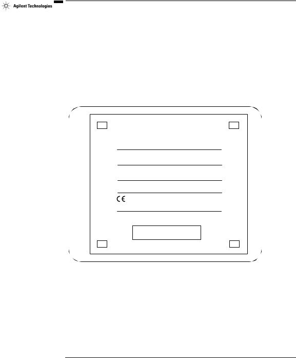
Step 1: Record LAN Hardware Address
First, find the hardware address of the LAN interface in the E2050 LAN/GPIB Gateway. Turn the Gateway over and look for the label on the underside of the Gateway. The hardware address on the label will be similar to 0800XXXXXX. Write down this address, as you may need it later to configure the Gateway on the network.
CAUTION: Use only Agilent Technologies specified AC - DC adaptor.
CAUTION: No operator serviceable parts inside.
Refer servicing to qualified personnel.
POWER: Input: 5V DC, 6 watts
 N279
N279
ISM 1-A
Made in U.S.A. of domestic and foreign components
LAN HARDWARE ADDRESS 0800fffffef6
Finding the LAN Hardware Address (MAC) Step 2: Configure the Network
nIf you purchased the optional rack mount kit, follow that kit’s documentation to assemble the rack and to install the Gateway in the rack’s frame.
nMake sure the GPIB instrumentation you will connect to the Gateway is working properly and is connected to the GPIB bus.
Chapter 2 |
27 |
Installation
Installing the Hardware
Step 3: Connect the Gateway to the Network
CAUTION
Do not connect to both the RJ-45 and the BNC connectors on the Gateway. Only one connection to the LAN interface in the Gateway can be made at a time. Data loss may occur if you try to use both connectors simultaneously. The Gateway will automatically select the active port.
NOTE
To connect the Gateway to a ThickLAN or fiber optic network, see the hardware documentation for with your ThickLAN or fiber optic network to connect the LAN cable to the RJ-45 connector on the Gateway.
To connect the Gateway directly to a client computer system, you will need a special twisted-pair cable. Contact Agilent Technologies for more information.
nEthertwist Connection. For Ethertwist, connect the LAN cable to the RJ-45 connector on the back panel of the Gateway.
Connecting to an Ethertwist LAN Using an RJ-45 Connector
28 |
Chapter 2 |
Installation
Installing the Hardware
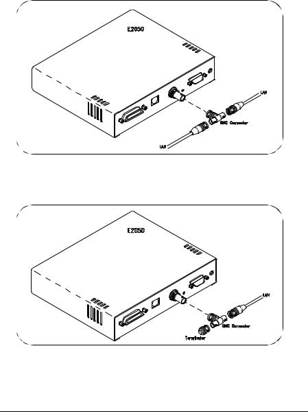
nThinLAN Connections. For ThinLAN, connect the LAN cable to the BNC connector on the back panel of the Gateway using a BNC “T” connector. Make sure the ThinLAN segment is properly terminated. If the Gateway is the end node on the LAN, a 50-ohm BNC terminator must be attached to the “T” connector.
Connecting to a ThinLAN Using a BNC “T” Connector
Connecting to a ThinLAN Using a BNC “T” Connector and 50-Ohm Terminator
Chapter 2 |
29 |
Installation
Installing the Hardware
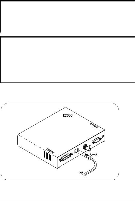
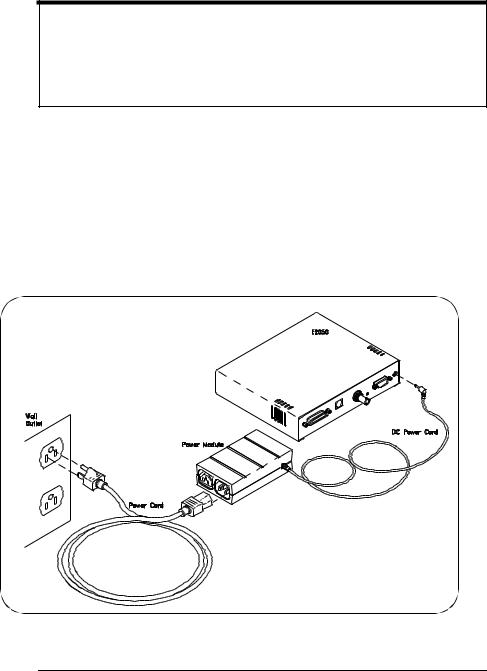
Step 4: Connect GPIB Cable and Power Cords
NOTE
The power module and Gateway do not have power switches. Connecting the standard AC power cord to the power source (wall outlet) activates both units. The power module automatically adapts to the correct AC voltage range for your power source.
nConnect the GPIB cable from the GPIB instrument(s) to the GPIB connector on the back panel of the Gateway.
nConnect the DC power cord attached to the power module (AC/DC Adapter) to the power input on the back panel of the Gateway, as shown.
nConnect the standard AC power cord to AC IN on the power module and to a power outlet (wall outlet), as shown.
Connecting the Power Module
30 |
Chapter 2 |
Loading...