


 Loading...
Operating Guide
This guide describes how to use the Agilent 53150A, 53151A, and 53152A Microwave Frequency Counters. The information in this guide applies to instruments having the number prefix listed below, unless accompanied by a “Manual Updating Changes” package indicating otherwise.
SERIAL PREFIX NUMBER: 3735A, US3925, and US4050 (53150A) 3736A, US3926, and US4051 (53151A) 3737A, US3927, and US4052 (53152A)
Agilent 53150A/151A/152A Microwave Frequency Counter
Copyright Agilent
Technologies, Inc. 1999, 2002
All Rights Reserved. Reproduction, adaptation, or translations without prior written permission is prohibited, except as allowed under the copyright laws.
Printed: August 2002
Printed in U.S.A.
Manual part number 53150-90013
Certification and Warranty
Certification
Agilent Technologies, Inc. certifies that this product met its published specification at the time of shipment from the factory. Agilent further certifies that its calibration measurements are traceable to the United States National Institute of Standards and Technology (formerly National Bureau of Standards), to the extent allowed by the Institute’s calibration facility, and to the calibration facilities of other International Standards Organization members.
Warranty
Agilent warrants Agilent hardware, accessories and supplies against defects in materials and workmanship for a period of one year from date of shipment. If Agilent receives notice of such defects during the warranty period, Agilent will, at its option, either repair or replace products which prove to be defective. Replacement products may be either new or like-new.
Agilent warrants that
Agilent software will not fail to execute its programming instructions, for the period specified above, due to defects in material and workmanship when properly installed and used. If Agilent receives notice of such defects during the warranty period, Agilent will replace software media which does not execute its programming instructions due to such defects.
For detailed warranty information, see back matter.
Safety Considerations
General
This product and related documentation must be reviewed for familiarization with this safety markings and instructions before operation.
Before Cleaning
Disconnect the product from operating power before cleaning.
Warning Symbols That May
Be Used In This Book
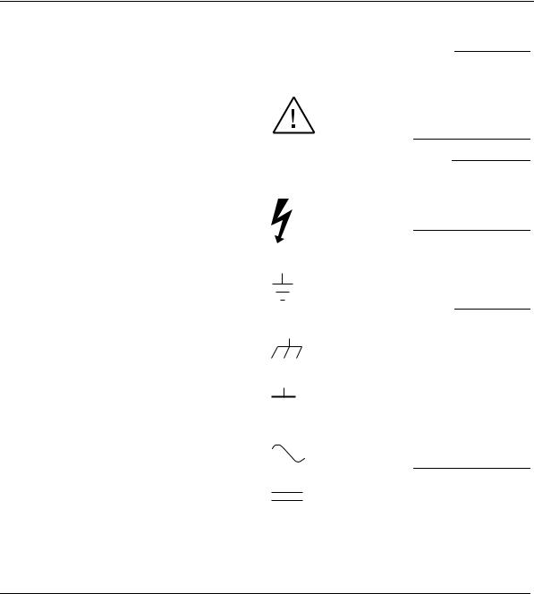
Instruction manual symbol; the product will be marked with this symbol when it is necessary for the user to refer to the instruction manual.
Indicates hazardous voltages.
Indicates earth (ground) terminal.
or
Indicates terminal is connected to chassis when such connection is not apparent.
Indicates Alternating current.
Indicates Direct current.
Safety Considerations (cont’d)
WARNING
BODILY INJURY OR DEATH MAY RESULT FROM FAILURE TO HEED A WARNING. DO NOT PROCEED BEYOND A WARNING UNTIL THE INDICATED CONDITIONS ARE FULLY UNDERSTOOD AND MET.
CAUTION
Damage to equipment, or incorrect measurement data, may result from failure to heed a caution. Do not proceed beyond a CAUTION until the indicated conditions are fully understood and met.
Safety Earth Ground
An uninterruptible safety earth ground must be maintained from the mains power source to the product’s ground circuitry.
WARNING
WHEN MEASURING POWER LINE SIGNALS, BE EXTREMELY CAREFUL AND ALWAYS USE A STEP-DOWN ISOLATION TRANSFORMER WHICH OUTPUT IS COMPATIBLE WITH THE INPUT MEASUREMENT CAPABILITIES OF THIS PRODUCT. THIS PRODUCT’S FRONT AND REAR PANELS ARE TYPCIALLY AT EARTH GROUND. THUS, NEVER TRY TO MEASURE AC POWER LINE SIGNALS WITHOUT AN ISOLATION TRANSFORMER.
For additional safety and acoustic noise information, see back matter.
Agilent Technologies, Inc. |
7.C.NL.06.15.01.R1.M.CW6FC |
5301 Stevens Creek Boulevard |
|
Santa Clara, California 95052-8059 |
|

Contents
|
Contents and Organization |
viii |
|
|
|
|
|
|
|
Related Documents |
ix |
|
|
|
|
|
|
|
Types of Service Available if Instrument Fails |
x |
|
|||||
|
Repackaging for Shipment |
xi |
|
|
|
|
|
|
|
Description of the Microwave Frequency Counter |
xii |
||||||
|
Options xiii |
|
|
|
|
|
|
|
|
Accessories Supplied and Available |
xiv |
|
|
||||
|
Agilent 53150A/151A/152A Quick Reference Guide |
xv |
||||||
1 |
Getting Started |
|
|
|
|
|
|
|
|
The Front Panel at a Glance |
1-2 |
|
|
|
|
||
|
The Front Panel Indicators at a Glance |
1-3 |
|
|
||||
|
The Front Panel Menus at a Glance |
1-4 |
|
|
||||
|
The Display Annunciators at a Glance |
1-5 |
|
|
||||
|
The Display Special Characters at a Glance |
1-6 |
|
|||||
|
The Rear Panel at a Glance |
1-7 |
|
|
|
|
||
|
Operating the Counter 1-8 |
|
|
|
|
|
||
|
Turning the Counter On |
1-10 |
|
|
|
|
||
|
Turning the Display Backlight Off or On |
1-11 |
|
|||||
|
Using the Menu |
1-12 |
|
|
|
|
|
|
|
Displaying the Menu |
1-12 |
|
|
|
|
||
|
Navigating in the Menu and Changing Settings 1-12 |
|||||||
|
Setting the Serial Port Baud Rate (Menu Example) 1-15 |
|||||||
|
Selecting the Input Channel |
1-16 |
|
|
|
|||
|
Measuring Frequency |
1-17 |
|
|
|
|
|
|
|
Measuring Relative Frequency |
1-19 |
|
|
||||
|
Offsetting a Frequency Measurement 1-20 |
|
||||||
|
Measuring Power (Channel 2 Only) |
1-22 |
|
|||||
|
Selecting the Unit of Measurement for Power |
1-23 |
||||||
|
Measuring Relative Power |
1-24 |
|
|
|
|||
|
Offsetting a Power Measurement |
|
1-24 |
|
|
|||
Operating Guide |
iii |

Contents
Using Power Correction |
1-26 |
|
|
Power Correction Theory of Operation |
1-26 |
||
Increasing Profile Accuracy |
1-27 |
|
|
Selecting a Power-Correction Profile |
1-28 |
||
Entering Data Points in a Power-Correction Profile 1-28 |
|||
Setting the Measurement Rate |
1-32 |
|
|
Setting the Number of Averages |
1-33 |
|
|
Setting the Resolution |
1-34 |
|
|
2 Operating Your Frequency Counter
Introduction 2-2 |
|
|
|
|
|
|
Chapter Summary |
2-2 |
|
|
|
|
|
How this Counter Works for You |
2-3 |
|
||||
Summary of the Measurement Sequence 2-4 |
||||||
Using the Selection Keys 2-5 |
|
|
|
|||
Sequencing Through the Menu |
2-5 |
|||||
Numeric Entry |
2-6 |
|
|
|
|
|
Changing States |
|
2-7 |
|
|
|
|
Using the Clear and Reset/Local Keys |
2-9 |
|||||
Acknowledging Messages |
2-9 |
|
|
|||
Other Function Selection Keys |
2-10 |
|
||||
Measuring Frequency |
2-12 |
|
|
|
|
|
Setting the Resolution and the Measurement Rate 2-14 |
||||||
Setting the Resolution |
2-14 |
|
|
|||
Resolution Setting Example |
2-15 |
|||||
Setting the Measurement Rate |
2-16 |
|||||
Rate Setting Example |
2-16 |
|
|
|||
Setting the Number of Averages |
2-17 |
|
||||
Averages Setting Example |
2-17 |
|||||
Measuring Relative Frequency |
2-20 |
|
||||
Relative Frequency Example |
|
2-20 |
||||
Offsetting a Frequency Measurement |
2-21 |
|||||
Frequency Offset Example |
2-21 |
|||||
Measuring Power |
2-24 |
|
|
|
|
|
Power Measurement Example |
2-24 |
|||||
iv |
Operating Guide |

Contents
Measuring Relative Power |
2-26 |
|
|
|
|
|
|
Relative Power Example |
2-26 |
|
|
|
|||
Offsetting a Power Measurement |
|
2-27 |
|
|
|
||
Power Offset Example 2-27 |
|
|
|
||||
Using Power Correction 2-30 |
|
|
|
|
|
||
Power Correction Theory of Operation |
2-31 |
|
|||||
Increasing Profile Accuracy |
2-32 |
|
|
|
|||
Power Correction Examples |
2-32 |
|
|
|
|||
Power Correction Example: Selecting a Correction Profile |
2-33 |
||||||
Power Correction Example: Editing Data Point Values |
2-35 |
||||||
Using the Menu |
2-39 |
|
|
|
|
|
|
Navigating in the Menu and Changing Settings 2-41 |
|
||||||
Reference Oscillator (REF OSC) |
2-42 |
|
|
||||
Do Self Test 2-43 |
|
|
|
|
|
|
|
Battery Voltage (BATT VOLTAGE) |
2-43 |
|
|||||
Operating Hours (OP HOURS) 2-43 |
|
|
|||||
Model Number, Firmware Version, Serial Number, |
|
||||||
and Option Codes |
2-43 |
|
|
|
|
||
Preset |
2-45 |
|
|
|
|
|
|
RS-232 Serial Port Data Rate (BAUD) |
2-46 |
|
|||||
Frequency Modulation (FM) |
2-46 |
|
|
||||
Channel 1 Low-Pass Filter (CH1 LPF) |
2-46 |
|
|||||
Recall User Settings (RECALL) |
2-46 |
|
|
||||
Save User Settings (SAVE) |
2-46 |
|
|
|
|||
Power Correction (PWR CORR) |
2-46 |
|
|
||||
3 Specifications
Introduction 3-2
A Rack Mounting the Counter
Rack Mounting the Counter A-2
Operating Guide |
v |

Contents
B |
Messages |
|
|
Overview B-2 |
|
|
Status Messages |
B-2 |
|
Self-Test Messages B-3 |
|
|
Error Messages |
B-4 |
C Using the Battery Option
Overview C-2
Operating the Counter from the Batteries C-2 Operating the Counter from a DC Power Source C-3
Replacing the Batteries |
C-4 |
Removing the Batteries C-4 |
|
Installing Batteries |
C-5 |
Charging the Batteries |
C-8 |
Precautions C-9 |
|
vi |
Operating Guide |

In This Guide
This book is the operating guide for the Agilent 53150A (20 GHz), 53151A (26.5 GHz), and 53152A (46 GHz) Frequency Counters. It consists of a table of contents, this preface, a quick reference guide, three chapters, three appendices, and an index.
This preface contains the following information:
• |
Contents and Organization |
pg. viii |
• |
Related Documents |
pg. ix |
• Types of Service Available if Instrument Fails |
pg. x |
|
• |
Repackaging for Shipment |
pg. xi |
• Description of the Microwave Frequency Counter |
pg. xii |
|
• |
Options |
pg. xiii |
• Accessories Supplied and Available |
pg. xiv |
|
• |
Manuals Supplied |
pg. xiv |
Operating Guide |
vii |

In This Guide
Contents and Organization
The Quick Reference Guide consists of a Menu Tree (tear-out sheet) that serves as a tool to trigger your memory or get you quickly reacquainted with the instrument.
Chapter 1 Getting Started is a quick-start guide that gives you a brief overview of the Counter’s keys, indicators, menus, display, and connectors. A graphical procedure for performing a measurement is
also provided.
Chapter 2 Operating Your Instrument is an operator’s reference. You are given an overview of each group of front-panel keys, operating functions, and menus followed by a series of exercises that guide you through the operation of the Counter.
Chapter 3 Specifications lists the specifications and characteristics of the Counter.
Appendix A Rack Mounting the Counter provides rack-mounting procedures for the Counter.
Appendix B Messages lists and explains all of the messages that are displayed on the Counter’s front panel and/or sent over the RS-232 serial interface.
Appendix C Using the Battery Option explains how to use the Counter with the Battery option.
Index
viii |
Operating Guide |

In This Guide
Related Documents
For more information on frequency counters refer to the following Series 200 Application Notes:
•Fundamentals of Electronic Frequency Counters, Application Note 200—Agilent part number 02-5952-7506.
•Understanding Frequency Counter Specifications, Application Note 200-4—Agilent part number 02-5952-7522.
•Fundamentals of Time and Frequency Standards, Application Note 52-1—Agilent part number 02-5952-7870.
Operating Guide |
ix |

In This Guide
Types of Service Available if Instrument Fails
If your Counter fails within one year of original purchase, Agilent will repair it free of charge. If your instrument fails after your one-year warranty expires, Agilent will repair it, or you can repair it yourself.
There are three types of repair services:
•Standard repair service—if downtime is not critical.
•Express Repair/Performance Calibration Service—if downtime is critical.
•Owner repair—repair the unit yourself using the Assembly-Level Service Guide.
Standard Repair Services (Worldwide)
Contact your nearest Agilent Service Center to arrange to have your Counter repaired.
Express Repair/Performance Calibration
Service (USA Only)
If downtime is critical, you can receive your repaired Counter via overnight shipment. Just call 1-800-403-0801 and ask for Express Repair/Performance Calibration Service. When your Counter is repaired, it will be returned via overnight shipment.
Repair Instrument Yourself
If you choose to repair the instrument yourself or would like more details on self test and calibration, use the procedures in the Assembly-Level Service Guide.
x |
Operating Guide |
In This Guide
Repackaging for Shipment
For the Express Repair/Performance Calibration Service described above, return your failed Counter to the designated Agilent Service Center, using the instrument’s original shipping carton (if available). Agilent notifies you when your failed instrument is received.
If the instrument is to be shipped to Agilent for service or repair, be sure you do the following:
•Attach a tag to the instrument identifying the owner and indicating the required service or repair. Include the instrument model number and full serial number.
•Place the instrument in its original container (if available) with appropriate packaging material.
•Secure the container with strong tape or shipping bands.
If the original shipping container is not available, place your unit in a container with at least 4 inches of compressible packaging material around all sides of the unit. Use static free packaging materials to avoid additional damage to your unit.
Agilent suggests that you always insure shipments.
Operating Guide |
xi |

In This Guide
Description of the Microwave Frequency
Counter
The Agilent 53150A, 53151A, and 53152A Microwave Frequency Counters are capable of measuring frequencies from 10 Hz to 125 MHz on Channel 1 and from 50 MHz to 20 GHz (53150A), 26.5 GHz (53151A), and 46 GHz (53152A) on Channel 2. These frequency counters are also capable of measuring power on Channel 2 (in the same frequency ranges). All three Counters have a maximum frequency resolution of 1 Hz.
The Agilent 53150A/151A/152A provides GPIB and RS-232 serial interfaces and are suitable for bench-top and ATE operation.
The basic measurement functions of the Agilent 53150A/151A/152A include Frequency, Relative Frequency, Frequency Offset, and Power (including Power Offset and Relative Power). All of these features are accessible from the front panel and over the GPIB and RS-232 interfaces.
The Agilent 53150A/151A/152A includes the following additional measurement functions and features that are designed specifically for manufacturing and service applications:
•1, 2, 5, and 10 MHz external reference capability
•Optional high-stability oven oscillator for high-accuracy needs and lengthened calibration cycles
•Frequency and power offset capabilities for relative measurements
•SCPI programming capability
•Battery and dc input option for operation in locations where AC power is unavailable
•Optional soft carrying case for safe transportation and mobile use
Programmable control is performed via an GPIB or an RS-232 serial interface. The GPIB and RS-232C ports are standard for the Agilent 53150A, 53151A, and 53152A.
xii |
Operating Guide |

In This Guide
Options
The options available for the Agilent 53150A/151A/152A are listed below. Specifications for the options are listed in Chapter 3, “Specifications.” Options ordered with the Counter are installed at the factory and are ready for operation on delivery. Refer to the "Retrofitting Options" chapter in the Agilent 53150A/151A/152A Assembly-Level Service Guide for information on installing options in the field.
Hardware
•High Stability Oven Timebase, Option 001
•Battery/DC Power Input, Option 002
•Rack Mount Kit, Option 1CM
•Soft Carrying Case, Option 007
Support
•3-year Return to Agilent for Repair, Option W30
•3-year Return to Agilent for Calibration, Option W32
•3-year Return to Agilent for Standards Compliant Calibration, Option W34
•5-year Return to Agilent for Repair, Option W50
•5-year Return to Agilent for Calibration, Option W52
•5-year Return to Agilent for Standards Compliant Calibration, Option W54
Retrofit
•Options 001 and 002 can be installed only by authorized Agilent Technologies Repair Centers.
Operating Guide |
xiii |

In This Guide
Accessories Supplied and Available
Accessories Supplied
•Power cord, 2.3 meters (Part number dependent upon destination country)
•Fuse (Agilent P/N 2110-0007)
Accessories Available
•Soft Carrying Case, (Agilent P/N 53150-80016)
•Automotive Power Adapter (Agilent P/N 53150-60214)
•Battery (Agilent P/N 53150-80010)
•GPIB Cables (Agilent P/N 10833A/B/C/D)
•RS-232 Cable (Agilent P/N 53150-60215)
Manuals Supplied
Agilent 53150A/151A/152A Operating Guide
(Agilent P/N 53150-90013)
Agilent 53150A/151A/152A Programming Guide
(Agilent P/N 53150-90014)
Agilent 53150A/151A/152A Assembly-Level Service Guide
(Agilent P/N 53150-90015)
xiv |
Operating Guide |

Agilent 53150A/151A/152A
Quick Reference Guide
The Quick Reference Guide is designed for experienced users of the Agilent 53150A, 53151A, and 53152A. It is intended to be used as a tool to trigger your memory.
If you are using the Counter for the first time, Agilent recommends that you at least read Chapter 1, “Getting Started,” first.
The Quick Reference Guide, which follows this page, consists of a menu tree that may be torn out of the guide for external use.
Reference |
Quick |
|
|
xv

Quick |
Reference |
|
|
xvi

Agilent 53150A/151A/152A Frequency Counter
Menu
Reset/
Local
REF OSC > INT REF OSC > EXT
SAVE > 0 to 9
RECALL > 0 to 9
CH1 LPF > OFF CH1 LPF > ON
FM |
|
> AUTO |
||
|
|
|
|
|
FM |
> |
OFF |
||
|
|
|
|
|
BAUD |
> |
|
9600 |
|
|
|
|
|
|
BAUD |
> |
|
4800 |
|
|
|
|
|
|
BAUD |
> |
|
2400 |
|
|
|
|
|
|
BAUD |
> |
|
1200 |
|
|
|
|
|
|
BAUD |
> |
|
19200 |
|
|
|
|
|
|
BAUD |
> |
|
14400 |
|
PRESET
53150A |
> |
< 00-111-222 > |
< SN |
999999 > |
<OPTNS -- -- -- -- |
> |
OP 9999 HRS
BATT VOLTAGE
0.0 |
|
Freq |
Pwr |
GPIB |
|
Offset |
Offset |
||
DO SELF TEST |
Rate |
Avg |
Resol |
|
|
|
|
||
PWR CORR > OFF |
|
|
|
|
PWR CORR > |
0 |
00 000 000 000 000 |
± 00.00 |
GPIB± 00ADDR.00 > 0 |
|
|
|
||
PWR CORR > |
to |
49 999 999 999 999 |
± 99.99 |
GPIB ADDR > 30 |
9 |
|
|
|
|
|
|
Freq |
Pwr |
GPIB |
|
|
Offset |
Offset |
|
|
|
Rate |
Avg |
Resol |
RATE |
FAST |
AVERAGES |
01 |
RESOL |
1 HZ |
RATE |
MED |
AVERAGES |
99 |
RESOL |
10 KHZ |
RATE |
SLOW |
|
|
RESOL |
100 KHZ |
RATE |
HOLD |
|
|
RESOL |
1 MHZ |
Quick
Quick
Reference
Reference
QR-1

Quick |
Reference |
|
|
QR-2

1
Getting Started
1
Chapter 1 Getting Started
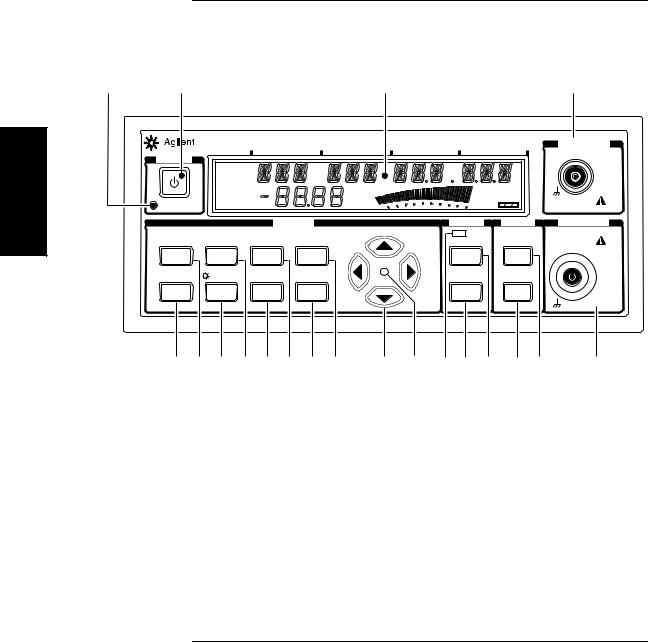
The Front Panel at a Glance
The Front Panel at a Glance
1 |
2 |
|
|
3 |
|
4 |
|
|
53150A |
|
|
20 GHz Counter |
CHANNEL 1 |
|
POWER |
GHz |
MHz |
kHz |
Hz |
10 Hz to 125 MHz |
|
Ch 12 |
|
|
|
|
|
|
|
|
|
|
|
|
|
|
Rel Freq |
|
|
|
1M Ω |
|
|
Offset |
|
|
|
|
|
|
dB |
|
Ext Rel Hold |
|
|
|
|
Avg On |
|
|
||
|
|
dBm |
|
Rate Rmt SRQ |
|
|
|
|
Rel Pwr |
Watts |
|
|
|
|
|
mW |
|
Error |
DAMAGE |
|
|
Standby |
Offset |
uW |
|
Shift |
|
|
% |
|
+30 dBm |
|||
|
|
|
|
|
|
|
|
|
MODIFY |
|
|
|
FREQ |
|
POWER |
|
CHANNEL 2 |
|
Freq |
Pwr |
|
|
|
|
Gate |
Channel 2 50 MHz to 20 GHz |
|||
Menu |
Offset |
Offset |
GPIB |
|
|
|
|
|
dBm/ W |
|
DAMAGE |
Reset/ |
Rate |
Avg |
Resol |
|
|
Chan |
|
Display |
|
+27 dBm |
|
|
|
|
|
|
|||||||
Local |
|
|
|
|
|
Select |
|
Power |
|
|
|
|
On/Off |
|
|
|
|
Rel Freq |
|
Rel Pwr |
|
50 Ω |
|
|
|
|
|
|
|
|
|
||||
Shift |
Clear |
+/- |
Enter |
|
|
Offset |
|
Offset |
|
|
|
|
|
|
|
|
|
On/Off |
|
On/Off |
|
|
|
20 19 18 17 16 15 14 13 |
12 |
11 |
10 |
9 |
8 |
7 |
6 |
5 |
|||
1 |
Standby indicator |
11 Selection keys active indicator |
|
2 |
Power/Standby switch |
12 |
Selection (arrow) keys |
3 |
LCD display |
13 |
Resolution / GPIB key |
4 |
Channel 1 input connector |
14 |
Enter key |
5 |
Channel 2 input connector |
15 |
Average / Power Offset key |
6 |
Display Power / dBm/W key (Channel 2) |
16 |
Sign (+/–) key |
7 |
Offset On/Off / Relative Power key |
17 |
Rate / Frequency Offset key |
|
(Channel 2) |
18 |
Clear / Backlight On/Off key |
|
|
||
8 |
Channel Selection key |
19 |
Reset/Local / Menu key |
|
|
||
9 |
Offset On/Off / Relative Frequency key |
20 |
Shift key |
|
|
||
10 |
Gate indicator |
|
|
1-2 |
Operating Guide |
NOTE
Chapter 1 Getting Started
The Front Panel Indicators at a Glance
The Front Panel Indicators at a Glance
The front panel includes three LED indicators. These are listed and described in the following table.
Indicator |
Description |
||
|
|
|
|
|
|
|
The Standby indicator is lit whenever the Main ~ |
|
|
|
Power switch on the rear panel is turned ON, and |
|
POWER |
the POWER switch on the front panel is OFF (out). |
|
|
During Standby, most of the instrument’s circuits do |
||
|
|
|
|
|
|
|
not receive power. However, the timebase and the |
|
|
|
|
|
|
|
cooling fan are powered so that the temperature in |
|
Standby |
the timebase components remains stable, and if the |
|
|
Battery option is installed, the battery-charging |
||
|
|
|
|
|
|
|
circuits are powered. When you press the POWER |
|
|
|
switch on the front panel, the Standby indicator goes |
|
|
|
off, and all of the Counter’s circuits receive power. |
|
|
|
|
|
|
|
When the LED indicator between the arrow keys |
|
|
|
flashes, the arrow keys can be used to navigate and |
|
|
|
change values in menus. |
|
|
|
When you make a change in a menu, always press |
|
|
|
the Enter key to save the setting and exit the menu. |
|
|
|
|
|
|
|
The Gate LED indicator flashes to indicate the rate |
|
FREQ |
at which measurements are triggered. The flash rate |
|
|
|
Gate |
of the LED varies with the settings of the |
|
|
||
|
|
|
measurement rate (Rate key) and the measurement |
|
Chan |
resolution (Resol key). The flash rate of the LED |
|
|
Select |
provides a rough indication of the number of |
|
|
|
|
|
|
|
|
measurements that are being taken in a given period |
|
|
|
of time. |
|
|
|
|
It is normal for the fan in the Counter to run when the Counter is in Standby mode. Power is supplied to the timebase whenever the
Main ~ Power switch is on to maintain long term measurement reliability, and the fan helps maintain timebase temperature stability.
1
Operating Guide |
1-3 |
1
Chapter 1 Getting Started
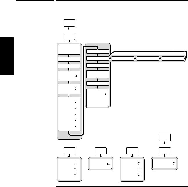
The Front Panel Menus at a Glance
The Front Panel Menus at a Glance
Shift
Menu
Reset/
Local
REF OSC > INT REF OSC > EXT
SAVE > 0 to 9
RECALL > 0 to 9
CH1 LPF > OFF CH1 LPF > ON
FM |
|
> AUTO |
||
|
|
|
|
|
FM |
> |
OFF |
||
|
|
|
|
|
BAUD |
> |
|
9600 |
|
|
|
|
|
|
BAUD |
> |
|
4800 |
|
|
|
|
|
|
BAUD |
> |
|
2400 |
|
|
|
|
|
|
BAUD |
> |
|
1200 |
|
|
|
|
|
|
BAUD |
> |
|
19200 |
|
|
|
|
|
|
BAUD |
> |
|
14400 |
|
Rate
PRESET |
|
|
|
|
53150A |
> |
< 00-111-222 > |
< SN 999999 > |
<OPTNS -- -- -- -- > |
OP 9999 |
HRS |
|
|
|
BATT VOLTAGE 0.0
DO SELF TEST
PWR CORR > OFF
PWR CORR > 0 to PWR CORR > 9
Shift
GPIB
Avg |
Resol |
Resol |
RATE |
FAST |
AVERAGES |
01 |
RESOL |
1 HZ |
GPIB ADDR |
0 |
RATE |
MED |
AVERAGES |
99 |
RESOL |
10 KHZ |
GPIB ADDR |
30 |
RATE |
SLOW |
|
|
RESOL |
100 KHZ |
|
|
RATE |
HOLD |
|
|
RESOL |
1 MHZ |
|
|
1-4 |
Operating Guide |
Chapter 1 Getting Started
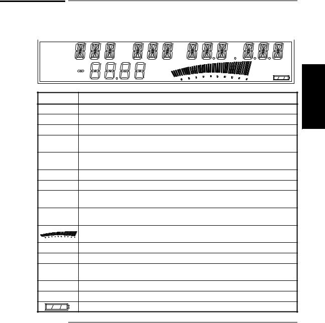
The Display Annunciators at a Glance
The Display Annunciators at a Glance
|
GHz |
|
MHz |
|
kHz |
|
Hz |
|
|
|
|
|
|
|
Ch 12 |
|
|
|
Rel Freq |
|
|
|
Offset |
dB |
Ext Rel Hold |
|
Avg On |
|||
dBm |
Rate Rmt SRQ |
||
Rel Pwr |
Watts |
|
|
mW |
Error |
||
Offset |
uW |
Shift |
|
% |
|||
Annunciator |
Description |
|
|
Ch 1 or Ch 2 |
Indicates which channel is selected to measure an input signal. |
|
|
Freq |
Indicates that the value displayed is a frequency reading. |
|
|
Rel Freq |
The displayed frequency value is relative to a previously zeroed value. |
||
Freq |
The displayed frequency value is offset by a previously entered frequency value. |
||
Offset |
|
|
|
Avg On |
The displayed frequency value is the result of a number of individual frequency |
||
|
measurements that have been averaged. |
|
|
Pwr |
The Counter is set to measure Power (Channel 2 only). |
|
|
Rel Pwr |
The displayed power measurement is relative to a previously zeroed power value. |
||
Pwr |
The displayed power value is offset by a previously entered power value. |
||
Offset |
|
|
|
dB, dBm, W, |
Indicates the unit of measurement for the currently displayed power value. |
||
mW, W, % |
|
|
|
|
Provides a real-time analog representation of the Power measurement (intended for |
||
|
peaking and similar procedures). |
|
|
Ext Ref |
The Counter is using an external reference signal for frequency measurements. |
||
Hold |
Indicates the Counter is in Hold (single-measurement) mode. |
|
|
Rmt, SRQ |
Shows the current state of the GPIB interface |
|
|
|
(Rmt = Remote operation via GPIB; SRQ = Service ReQuest). |
|
|
Error |
Indicates that a front-panel key command is unacceptable in the current context. |
||
Shift |
Indicates that all front-panel keys are redefined to the function printed above the key. |
||
|
Shows the amount of charge in the batteries (if the Battery option is installed). |
||
1
Operating Guide |
1-5 |

Chapter 1 Getting Started
The Display Special Characters at a Glance
1
NOTE
The Display Special Characters at a Glance
Special Description
Characters
Points to the current value for a Menu setting.
Indicates that the value for the current Menu setting can be changed using the selection (arrow) keys.
When the letter “c” is displayed in the hundredths position of the power display, Power Correction mode is in effect.
The first two special characters shown above are intended to help you navigate within the Menu. When the right pointer (  ) is flashing, it indicates the current setting for the selected Menu option. When the left pointer (
  ) is flashing, it indicates that you can use the selection (arrow) keys to change the setting for the current Menu option.
1-6 |
Operating Guide |
Chapter 1 Getting Started
The Rear Panel at a Glance
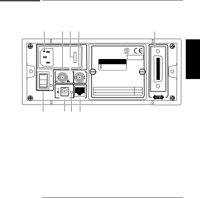
The Rear Panel at a Glance
1 |
2 |
3 |
4 |
5 |
|
6 |
|
|
|
|
Made in U.S.A. |
ISM 1-A |
|
|
|
|
|
with domestic and foreign content |
1 |
|
|
|
|
|
|
||
|
|
|
|
OPTIONS |
|
|
|
|
|
|
|
|
|
|
|
|
|
001 Oven Time Base |
|
|
|
|
|
|
002 Battery |
|
|
Main ~ Power |
Reference 10 MHz |
Auxillary |
|
|
|
|
|
WARNING: |
|
|
|||
|
|
In |
|
|
|
|
|
|
|
To avold electric shock, |
|
|
|
|
|
or |
|
|
|
|
|
|
Out |
|
do not remove covers. |
|
|
|
|
|
|
|
|
|
No user-serviceable parts inside.
Refer all servicing to qualified personnel.
This unit must be earth grounded.
11 TO 18 VDC |
|
|
|
|
AC POWER |
FUSE |
|
|
100 |
– 130 VAC, 50/60/400 Hz 75 VA |
1.0 A T |
|
220 |
– 240 VAC, 50/60 Hz 75 VA |
250 V |
EXT DC |
RS-232 |
|
|
10 |
9 |
8 |
7 |
1AC Input/Power module (Senses incoming voltage and adjusts automatically)
2External Reference connector (BNC) 1, 2, 5, or 10 MHz Input
10 MHz Output
3Fuse Holder (behind door)
4Auxiliary connector (reserved)*
5Battery compartment (optional) or cover plate
6GPIB (IEEE-488.1) Interface connector
7RS-232 Interface connector (RJ12)
8Main AC Power On indicator
9EXT DC power-input connector (functional only when Battery option is installed)
10Main ~ Power switch
* The Auxiliary connector is not installed on standard production units.
Operating Guide |
1-7 |

1
Chapter 1 Getting Started
Operating the Counter
Operating the Counter
The procedures in this section are designed to familiarize you with the Frequency Counter’s features and controls. Agilent suggests that you follow the steps for each of these procedures, even if you do not presently need to make any measurements or to adjust any of the Counter’s settings. The following procedures are provided:
•Turning the Counter On
•Turning the Display Backlight Off or On
•Selecting an Input Channel
•Using the Menu
•Setting the Serial Port Baud Rate
•Measuring Frequency
•Measuring Relative Frequency
•Offsetting a Frequency Measurement
•Measuring Power
•Measuring Relative Power
•Offsetting a Power Measurement
•Using Power Correction
•Setting the Measurement Rate
•Setting the Number of Averages
•Setting the Resolution
1-8 |
Operating Guide |
Chapter 1 Getting Started
Operating the Counter
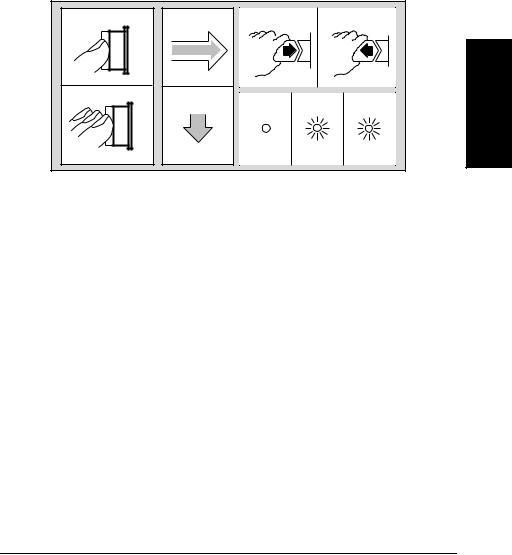
The following legend defines the meanings of the icons used throughout this chapter.
|
|
Legend |
|
|
|
1 |
3 |
5 |
|
6 |
|
2 |
4 |
7 |
8 |
9 |
1 |
|
|
|
1 |
Press key one |
3 |
Result |
7 |
Indicator off |
|
|
time and release |
4 |
Auto operation |
8 |
Indicator on |
|
2 |
Multiple key |
|||||
5 |
Connect signal |
9 |
Indicator flashing |
|||
|
presses |
|||||
|
6 |
Disconnect signal |
|
|
||
|
|
|
|
Operating Guide |
1-9 |
Chapter 1 Getting Started
Operating the Counter
Turning the Counter On
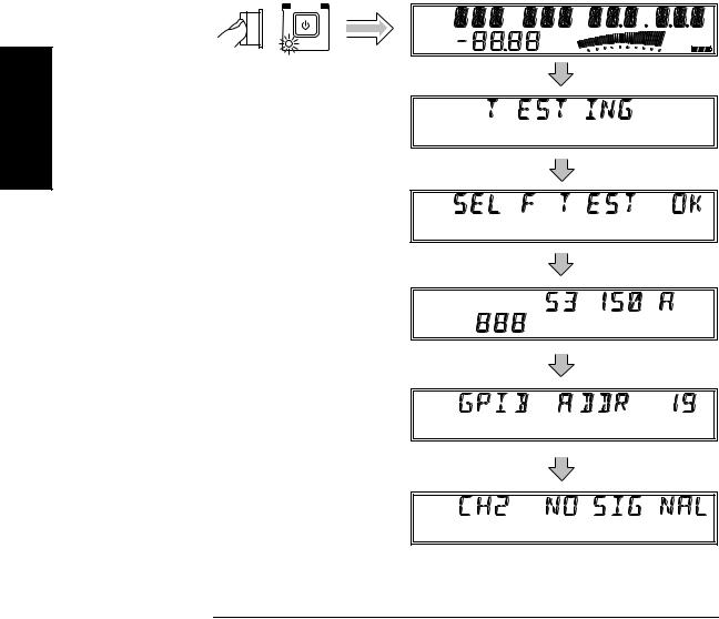
To turn on the Counter, turn on the Main ~ Power switch on the rear panel (see page 1-7), and then press and release the POWER button on the front panel.
POWER
Ch 12
Rel Freq
Offset
Avg On
Standby |
Rel Pwr |
|
Offset |
dB |
Ext Rel Hold |
dBm |
Rate Rmt SRQ |
Watts |
|
mW |
Error |
uW |
Shift |
% |
1
Ch 2
Freq
1-10 |
Operating Guide |
NOTE
NOTE
NOTE
Chapter 1 Getting Started
Operating the Counter
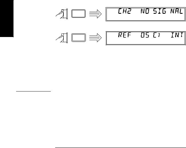
If a signal was applied to the Channel 2 input connector prior to turning on the Counter, CH2 NO SIGNAL is displayed momentarily. As soon as the Counter acquires the input signal, it displays the signal’s value.
The internal Reference Oscillator requires 10 to 15 minutes to reach a stable operating temperature. Since the Reference Oscillator receives power only when the Counter is on or in Standby mode, no measurements should be taken unless the Counter’s Main ~ Power switch has been in the on (1) position for at least that amount of time.
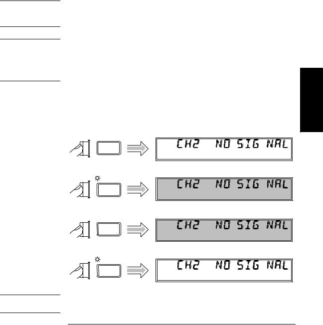
Turning the Display Backlight Off or On
When you first turn the Counter on, the backlight for the LCD display is always lit. You can toggle the backlight off and on by pressing the Shift key and then the  On/Off (Clear) key, as shown below.
|
Ch 2 |
Shift |
Freq |
Shift
On/Off
Ch 2
Freq
Clear
|
Ch 2 |
Shift |
Freq |
Shift
On/Off
Ch 2
Freq
Clear
If your Counter has the Battery option, you can extend the length of time the Counter can operate from the batteries by turning off the display backlight.
1
Operating Guide |
1-11 |
1
Chapter 1 Getting Started
Operating the Counter
Using the Menu
The Agilent 53150A/151A/152A Counter has one menu that you use to control a number of the Counter’s features and functions.
Displaying the Menu
To display the Menu, press the Shift key and then the Menu (Reset/Local) key, as shown below.
|
Ch 2 |
Shift |
Freq |
Shift
Menu
Reset/
Local
Navigating in the Menu and Changing Settings
Use the Selection (arrow) keys to navigate to the setting you want to change and then to actually make the changes. For example, the diagram on the next page shows how to change the setting of the Reference Oscillator from INTernal to EXTernal. (In this example, a reference signal is applied to the External Reference connector, but no signal is applied to the Channel 2 input.)
NOTE |
The Counter will not switch to EXTernal unless a suitable reference |
|
signal is available at the External Reference connector. |
1-12 |
Operating Guide |
Loading...