


 Loading...
Agilent G3180B
Two-Way Splitter Kit
With Makeup Gas
Installation and Operation
Guide


 Agilent Technologies

Notices
©Agilent Technologies, Inc. 2006
No part of this manual may be reproduced in any form or by any means (including electronic storage and retrieval or translation into a foreign language) without prior agreement and written consent from Agilent Technologies, Inc. as governed by United States and international copyright laws.
Manual Part Number
G3180-90120
Supercedes G3180-90110
Edition
First edition, April 2006
Printed in USA
Agilent Technologies, Inc.
2850 Centerville Road
Wilmington, DE 19808-1610 USA
Acknowledgement
Microsoft® is a U.S. registered trademark of Microsoft Corporation.
Warranty
The material contained in this document is provided “as is,” and is subject to being changed, without notice, in future editions. Further, to the maximum extent permitted by applicable law, Agilent disclaims all warranties, either express or implied, with regard to this manual and any information contained herein, including but not limited to the implied warranties of merchantability and fitness for a particular purpose. Agilent shall not be liable for errors or for incidental or consequential damages in connection with the furnishing, use, or performance of this document or of any information contained herein. Should Agilent and the user have a separate written agreement with warranty terms covering the material in this document that conflict with these terms, the warranty terms in the separate agreement shall control.
Safety Notices
CAUTION
A CAUTION notice denotes a hazard. It calls attention to an operating procedure, practice, or the like that, if not correctly performed or adhered to, could result in damage to the product or loss of important data. Do not proceed beyond a CAUTION notice until the indicated conditions are fully understood and met.
WARNING
A WARNING notice denotes a hazard. It calls attention to an operating procedure, practice, or the like that, if not correctly performed or adhered to, could result in personal injury or death. Do not proceed beyond a WARNING notice until the indicated conditions are fully understood and met.
2 |
Installation and Operation Guide |
In this Guide. . .
This Installation and Operation Guide contains information for installing and using an effluent splitter on an Agilent 6890 gas chromatograph (GC). The G3180 splitter is intended for use with capillary columns and uses makeup gas to maintain adequate flows throughout the system.
1Introduction
This chapter describes how the splitter works, the GC and software requirements of the system and the contents of the installation kit.
2Hardware Installation
See this chapter for a detailed procedure for installing the splitter hardware and connecting the makeup gas supply.
3Splitter Configurations
The split ratio (how the column effluent divides between the two detectors) is governed by two restrictors, which are lengths of deactivated fused silica tubing. This chapter presents a set of precalculated “typical” configurations. If desired, you can create a custom configuration to meet specific needs. The chapter describes a set of software tools, included in the kit, to assist you in designing such configurations. Finally, installation of the column and restrictors is covered.
4Operation
This chapter contains a worked-out custom configuration, plus a few special topics.
Installation and Operation Guide |
3 |
4 |
Installation and Operation Guide |
Contents
1 Introduction |
|
|
|
Overview |
8 |
|
|
How It Works |
9 |
|
|
Details |
10 |
|
|
Metal ferrules |
10 |
||
Microfluidic plate 10 |
|||
Constant pressure operation 10 |
|||
Calculation of chromatographic parameters 11 |
|||
GC Requirements |
12 |
||
Other Requirements |
12 |
||
Parts Supplied |
13 |
|
|
Part Identification |
14 |
||
Parts Not Supplied |
15 |
||
Tools Required |
15 |
|
|
2 Hardware Installation |
|
Prepare the GC 18 |
|
Install the Column Clips 20 |
|
Install the Bracket and Splitter |
21 |
Connect the Makeup Gas Supply |
24 |
To supply the makeup gas froma PCM 24
To supply the makeup gas from an Auxiliary Pressure controller 24
Installation and Operation Guide |
5 |
3 Splitter Configurations |
|
|
|
Typical Configurations |
26 |
|
|
Splitting to an MSD |
28 |
|
|
Custom Configurations |
29 |
|
|
Restrictor id and length |
32 |
|
|
Maximum and minimum flows |
33 |
||
Column outlet pressure |
34 |
|
|
Inlet pressure 34 |
|
|
|
Restrictor and Column Installation |
35 |
||
Install the column |
35 |
|
|
Connect the splitter |
35 |
|
|
Disconnect tubing from the splitter 37 |
|||
4 Operation |
|
|
An Example 40 |
|
|
Column flow 40 |
|
|
Select restrictors 42 |
|
|
Calculate column flow |
43 |
|
Calculate ECD restrictor flow |
44 |
|
Calculate MSD restrictor flow |
45 |
|
Changing Columns Without Venting the MSD 46 |
||
Backflushing the Column |
47 |
|
6 |
Installation and Operation Guide |

Agilent G3180B Splitter Kit
Installation and Operation Guide
1 Introduction
Overview 8 |
|
|
|
How It Works |
9 |
|
|
Details 10 |
|
|
|
Metal ferrules |
10 |
|
|
Microfluidic plate |
10 |
||
Constant pressure operation 10 |
|||
Calculation of chromatographic parameters 11 |
|||
GC Requirements |
12 |
|
|
Other Requirements |
12 |
||
Parts Supplied |
13 |
|
|
Part Identification |
14 |
||
Parts Not Supplied |
15 |
||
Tools Required |
15 |
|
|
This manual covers the installation and operation of the G3180B effluent splitter with makeup gas kit on the Agilent 6890 series gas chromatograph (GC).
Agilent Technologies |
7 |
1 Introduction
Overview
Splitter installation is done in three steps:
1Hardware installation. This gets the hardware installed and the gas flows connected.
2Restrictor configuration. You can choose to use a typical, precalculated configuration or create a custom one using software tools supplied on a CD.
3Restrictor and column installation. Using the results of step 2, cut the appropriate lengths of the appropriate diameter tubing for the restrictors. Install the restrictors and the analytical column.
8 |
Installation and Operation Guide |
Introduction 1
How It Works
The splitter divides the effluent from a column between two different detectors. The detectors can be operating at different pressures, that is, any mix of the following can be used:
•Atmospheric pressure
FID (flame ionization detector) TCD (thermal conductivity detector) NPD (nitrogen phosphorus detector) ECD (electron capture detector) FPD (flame photometric detector)
•Below atmospheric pressure
MSD (mass selective detector)
•Above atmospheric pressure
AED (atomic emission detector)
The split ratio is determined by the length and diameter of tubing connecting the splitter to the detectors. Tubing dimensions may be determined from Table 2 on page 26 in this manual or from a spreadsheet calculator that is included for calculating tubing dimensions for special situations.
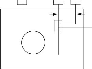
Figure 1 shows the plumbing configuration for the G3180B splitter.
Inlet |
Det 1 |
Det 2 |
|
Restrictor 1 |
Restrictor 2 |
|
Splitter |
Constant pressure |
|
|
|
|
|
makeup gas supply |
|
Column |
|
GC oven
Figure 1 Splitter plumbing
Installation and Operation Guide |
9 |
1 Introduction
The column flow mixes with the makeup flow in the splitter. This mixture then flows through lengths of uncoated, deactivated, fused-silica tubing to each detector. These tubes act as flow restrictors. While the flow through each restrictor changes with oven temperature, the ratio of the two flows at any temperature is the same.
Details
The G3180B kit addresses several limitations of previous approaches to splitting column effluent between two detectors:
Metal ferrules
The splitter uses metal column ferrules, which eliminate air leakage into the sample stream. Unlike polyimide, metal ferrules do not loosen upon thermal cycling of the oven. They also do not outgas contaminants or shed particles (like graphite) that can result in chromatographic problems.
Microfluidic plate
The splitting hardware is based on microfluidic plate technology. This allows very low dead volume connections between the column end and the two detector restrictor tubes. The thin metal plate has fast thermal response and is mounted solidly on the oven wall for ease of use. The interior plate surfaces are deactivated to prevent adsorption by active compounds.
Constant pressure operation
The splitter uses a source of makeup gas supplied by electronic pneumatics control (EPC). This maintains the splitter at a known and constant pressure. Constant pressure allows easier splitting to vacuum detectors like the MSD. It simplifies choice of splitter parameters, allowing all aspects of the chromatographic setup to be calculated. Constant pressure makeup allows the column to be run in constant flow mode while still maintaining a constant split ratio between two detectors of different operating pressures such as the FPD and the MSD. Because the EPC pressure can be time programmed, useful operations like backflushing unwanted heavy materials from the column and changing columns in MSD systems without venting are possible.
10 |
Installation and Operation Guide |
Introduction 1
Calculation of chromatographic parameters
Because the pressure at the split point is known and constant, the chromatographic parameters can be calculated before setup. This is especially useful with GC/MSD setups, where there are limitations on the flow rates of carrier gas allowed into the MSD. If a method that was originally developed on an MSD is converted to a splitter setup, a new inlet pressure can be calculated to produce retention times very similar to the original method.
Installation and Operation Guide |
11 |
1 Introduction
GC Requirements
The splitter mounts in an Agilent 6890 series GC.
The splitter requires an electronically controlled pressure source such as the Three Channel Pressure controller (6890 option 205, 301, or 308) or a Pneumatics Control Module (PCM).
Other Requirements
The calculator requires Microsof®t Excel 97 (or later), which is not supplied with this kit.
12 |
Installation and Operation Guide |
Introduction 1
Parts Supplied
The G3180B kit contains the following parts (Table 1).
Table 1 |
Parts supplied |
|
|
|
|
|
|
Part number |
Description |
Quantity |
|
|
|
|
|
0100-0124 |
|
Union, stainless steel, 1/16-inch tubing |
2 |
|
|
|
|
0100-0241 |
|
Union, stainless steel, 1/8 to 1/16-inch reducing |
1 |
|
|
|
|
G1580-00130 |
Valve box blanking plate |
1 |
|
|
|
|
|
G1530-01340 |
Capillary column spring clips |
4 |
|
|
|
|
|
0515-0374 |
|
Screw, M3 × 10 mm |
7 |
|
|
|
|
G2855-60140 |
Oven bracket assembly |
1 |
|
|
|
|
|
G2855-60560 |
T-screw oven bracket retainer |
2 |
|
|
|
|
|
G2855-80022 |
Manual and calculator CD |
1 |
|
|
|
|
|
G3180-90120 |
Manual, G3180B |
|
|
|
|
|
|
0100-2354 |
|
Tubing, stainless steel, 1/16-inch od × 0.01-inch id, 1 m |
1 |
|
|
|
|
G3180-61500 |
Compact splitter with makeup gas assembly |
1 |
|
|
|
|
|
G2855-60150 |
Supplies and spares kit |
1 |
|
|
|
|
|
Installation and Operation Guide |
13 |
1 Introduction
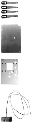
Part Identification
Most of the kit parts are easily recognized. The unique ones are identified in Figure 2.
Capillary column spring clips
Valve box blanking plate
Oven bracket assembly
Compact splitter with makeup gas assembly
This assembly is shipped in a plastic bag to keep contaminants out of the tubing and the fittings. Do not open the bag until you are ready to install the splitter.
Figure 2 Part identification
14 |
Installation and Operation Guide |
Introduction 1
Parts Not Supplied
Brown-dot frit (19231-60610)
Tools Required
Side cutter, large
Open-end wrenches
Installation and Operation Guide |
15 |
1 Introduction
16 |
Installation and Operation Guide |
Loading...