


 Loading...
Agilent G1978B Multimode Source for 6100 Series Single Quad LC/MS
Set-Up Guide


 Agilent Technologies

Notices
© Agilent Technologies, Inc. 2008
No part of this manual may be reproduced in any form or by any means (including electronic storage and retrieval or translation into a foreign language) without prior agreement and written consent from Agilent Technologies, Inc. as governed by United States and international copyright laws.
Manual Part Number
G1978-90070
Edition
First Edition, December 2008
Printed in USA
Agilent Technologies, Inc.
5301 Stevens Creek Blvd.
Santa Clara, CA 95051 USA
Windows® and MS Windows® are U.S. registered trademarks of Microsoft Corporation.
Windows NT® is a U.S. registered trademark of Microsoft Corporation.
Warranty
The material contained in this document is provided “as is,” and is subject to being changed, without notice, in future editions. Further, to the maximum extent permitted by applicable law, Agilent disclaims all warranties, either express or implied, with regard to this manual and any information contained herein, including but not limited to the implied warranties of merchantability and fitness for a particular purpose. Agilent shall not be liable for errors or for incidental or consequential damages in connection with the furnishing, use, or performance of this document or of any information contained herein. Should Agilent and the user have a separate written agreement with warranty terms covering the material in this document that conflict with these terms, the warranty terms in the separate agreement shall control.
Technology Licenses
The hardware and/or software described in this document are furnished under a license and may be used or copied only in accordance with the terms of such license.
Restricted Rights Legend
U.S. Government Restricted Rights. Software and technical data rights granted to the federal government include only those rights customarily provided to end user customers. Agilent provides this customary commercial license in Software and technical data pursuant to FAR 12.211 (Technical Data) and 12.212 (Computer Software) and, for the Department of Defense, DFARS 252.227-7015 (Technical Data - Commercial Items) and DFARS 227.7202-3 (Rights in Commercial Computer Software or Computer Software Documentation).
Safety Notices
CAUTION
A CAUTION notice denotes a hazard. It calls attention to an operating procedure, practice, or the like that, if not correctly performed or adhered to, could result in damage to the product or loss of important data. Do not proceed beyond a CAUTION notice until the indicated conditions are fully understood and met.
WARNING
A WARNING notice denotes a hazard. It calls attention to an operating procedure, practice, or the like that, if not correctly performed or adhered to, could result in personal injury or death. Do not proceed beyond a WARNING notice until the indicated conditions are fully understood and met.
2 |
Multimode Source for 6100 Series Single Quad LC/MS Set-Up Guide |
In This Guide
This guide explains how to install, maintain and troubleshoot your nanoelectospray ion source.
1Installation
This chapter tells you how to install the multimode ion source.
2Verification
This chapter tells you how to install the multimode ion source.
3Methods
This chapter describes basic operation and maintenance for the multimode ion source.
Multimode Source for 6100 Series Single Quad LC/MS Set-Up Guide |
3 |
4 |
Multimode Source for 6100 Series Single Quad LC/MS Set-Up Guide |
Content
1 |
Installation |
7 |
|
|
|
|
|
Installation |
8 |
|
|
|
|
|
Step 1. Prepare to install |
8 |
|
|
||
|
Step 2. Install the HV control PCA and cables |
9 |
|
|||
|
Changing Sources |
13 |
|
|
|
|
|
To remove the multimode source 13 |
|
|
|||
|
To convert from multimode to ESI, APCI or APPI |
14 |
|
|||
|
To convert from ESI, APCI or APPI to the multimode source |
15 |
||||
2 |
Verification |
21 |
|
|
|
|
|
To verify sensitivity for 6120 Quad - G1978B Multimode, Positive SIM |
|||||
|
Modes |
22 |
|
|
|
|
|
To verify sensitivity for 6130 and 6140 Quads - G1978B Multimode, Positive SIM |
|||||
|
Modes |
24 |
|
|
|
|
|
To verify sensitivity for 6130 and 6140 Quads - G1978B Multimode, Positive |
|||||
|
Scan Modes |
27 |
|
|
|
|
|
To verify sensitivity for the G1978B Multimode using Multiple FIA method in |
|||||
|
Mixed Mode operation |
30 |
|
|
||
|
To do an autotune |
32 |
|
|
|
|
|
Example of multimode verification report 33 |
|
|
|||
3 |
Methods 35 |
|
|
|
|
|
|
To setup a method to use the multimode source |
36 |
|
|||
|
To create a method for positive/negative mixed mode operation 37 |
|||||
|
To create a method for alternating ESI and APCI operation |
39 |
||||
Multimode Source for 6100 Series Single Quad LC/MS Set-Up Guide |
5 |
Contents
6 |
Multimode Source for 6100 Series Single Quad LC/MS Set-Up Guide |

Agilent G1978B Multimode Source for 6100 Series Single Quad LC/MS
Set-Up Guide
1 Installation
Installation 8
Step 1. Prepare to install 8
Step 2. Install the HV control PCA and cables 9
Changing Sources 13
To remove the multimode source 13
To convert from multimode to ESI, APCI or APPI 14
To convert from ESI, APCI or APPI to the multimode source 15
This chapter contains instructions to install the multimode source on a 6100 Series Single Quad LC/MS system, and also to remove and replace the source.
Agilent Technologies |
7 |
1Installation Installation
Installation
This section explains how to install the G1978B multimode source on a 6100 Series Single Quad LC/MS instrument. The G1978A multimode source is not supported on these instruments.
The 6100 Series Single Quad LC/MS with multimode source is supported on ChemStation B.03.01 or higher, or the ChemStation B.01.03 with a patch.
Step 1. Prepare to install
The Multimode Enablement Kit, G1978-60451, is shipped with the multimode source. This kit needs to be installed before the multimode source is used.
Note that the multimode source and its accessories are to be installed by an Agilent Customer Engineer.
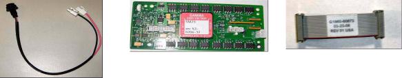
1Check that the Multimode Enablement Kit contains the following parts:
•Multimode Bd HV cable, p/n G1960-60858
•Multimode HV PCA, p/n G1960-61015
•Multimode Bd Power/Data Cable, p/n G1960-60873
Figure 1 From left to right: G1960-60858, G1960-61015 and G1960-60873
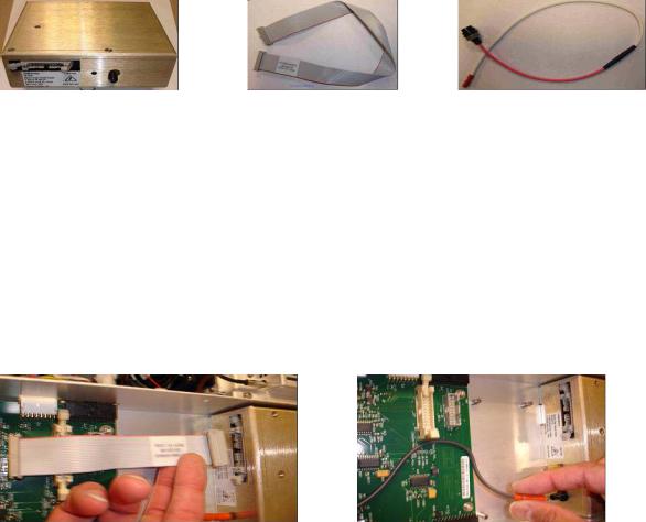
2Install the APCI Enablement Kit, G1947-60451, which is shipped with the multimode source.
The APCI Enablement kit contains the following parts:
• Fast APCI HV Supply, p/n G1946-80058
8 |
Multimode Source for 6100 Series Single Quad LC/MS Set-Up Guide |
Installation 1
Step 2. Install the HV control PCA and cables
•Valve BD-APCI supply, p/nG1960-60802
•Valve BD-APCI Needle Interlock, p/n G1960-60856
Figure 2 From left to right: G1946-80058, G1960-60802 and G1960-60856
Step 2. Install the HV control PCA and cables
1Turn off the system power and remove the system power cord.
Keep the power cord intact if the vacuum control switch box is used. The switch box is intended to keep the vacuum on while a CE works on the electronics. The switch box is for CE use only.
2Remove the CDS cover, top, side, front, and the Aux Module cover.
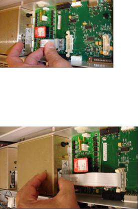
3Disconnect the ribbon cable that connects the valve PCA to the Vcap/Vchamber power supply. Then disconnect the Vcap and Vchamber cable from the power supply.
Figure 3 Disconnecting the Vcap/Vchamber power supply from the valve PCA (left) and the Vcap/Vchamber.
4Place the multimode HV power supply PCA in the slot between the valve PCA and the Vcap/Vchamber. Secure the board by pressing it down into its slot and then attach it with two screws.
5Connect the short gray cable from valve PCA to the multimode HV power supply.
Multimode Source for 6100 Series Single Quad LC/MS Set-Up Guide |
9 |
1Installation
Step 2. Install the HV control PCA and cables
Figure 4 Connecting the valve PCA to the multimode HV power supply.
6Install the APCI HV power supply. The APCI HV power supply is located at the end of the AUX Module.
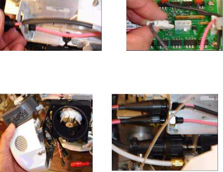
7Connect ribbon cable between valve PCA and Vcap/Vchamber power supply.
Figure 5 Connecting the valve PCA to the Vcap/Vchamber power supply.
8Connect the Vcap and Vchamber cables to the Vcap/Vchamber power supply.
10 |
Multimode Source for 6100 Series Single Quad LC/MS Set-Up Guide |

Installation 1
Step 2. Install the HV control PCA and cables
Figure 6 Connecting the Vcap and Vchamber cables to the power supply.
9Connect the long ribbon cable, p/n G1960-60802, from the APCI HV power supply to the valve PCA.
Figure 7 Connecting the APCI HV power supply to the valve PCA.
10Insert one end of the APCI Needle Interlock cable, G1960-60856, through the slot at the front of the system and then plug it to the APCI HV connector. Attach the other end to the chassis with the o-ring and the nut.
Figure 8 Connecting the APCI HV to the chassis.
11Insert the cable, G1960-60858, to the top slot and attach it to the chassis. Plug the other two ends into the multimode HV PCA.
Multimode Source for 6100 Series Single Quad LC/MS Set-Up Guide |
11 |
1Installation
Step 2. Install the HV control PCA and cables
Figure 9 Connecting the HV PCA to the chassis.
12 Close the AUX Module cover and reconnect all cables.
13 Install the multimode source to the system and connect all connectors.
Figure 10 Installing the multimode source (left) and connecting all connectors.
14 Put back the side, top, front and CDS cover.
15 Plug the system power cord back on and turn the front switch on.
The pump down process will start.
16 Start the ChemStation program.
17 Click Method and Run Control View > MSD > Spray Chamber and verify that the source is an MM Source.
18 Go to MSD Tune window and start the Auto tune with a multimode source.
19 Verify that the multimode source is working correctly.
12 |
Multimode Source for 6100 Series Single Quad LC/MS Set-Up Guide |
Installation 1
Changing Sources
Changing Sources
To remove the multimode source
Do the following steps to remove the multimode source.
1Set the source temperatures for vaporizer heater and drying gas heater to minimum values to cool the source.
Use the Tune > Instrument > Edit Spray Chamber menu item to display the Edit Spray Chamber dialog box. Set the drying gas flow, nebulizer gas flow, drying gas temperature and the vaporizer temperature to minimum values.
WARNING |
Do not touch the multimode source or the capillary cap. They may be very hot. Let |
||
the parts cool before you handle them. |
|||
|
|||
|
|
||
|
Never touch the source surfaces, especially when you analyze toxic substances or |
||
WARNING |
|||
when you use toxic solvents. The source has several sharp pieces which can pierce |
|||
|
|||
|
your skin including the APCI corona needle, vaporizer sensor and counter current |
||
|
electrode. |
||
|
|
||
|
Do not insert fingers or tools through the openings on the multimode chamber. When |
||
WARNING |
|||
in use, the capillary and capillary cap are at high voltages up to 4 kV. |
|||
|
|||
|
|
|
|
|
2 |
Wait approximately 20 minutes or until the source is cool. |
|
|
3 |
Open the CDS door at the front of the MS to access the cables. |
|
|
4 |
Disconnect the ESI high voltage charging electrode cable. |
|
|
5 |
Disconnect the APCI Needle Interlock and multimode HV cable. |
|
|
6 |
Unscrew the nebulizer gas line from the nebulizer. |
|
|
7 |
Unscrew the LC sample tubing from the nebulizer. |
|
|
8 |
Open the latch on the source and open the source. |
|
|
9 |
Remove the multimode source from the spray chamber mount. |
|
Multimode Source for 6100 Series Single Quad LC/MS Set-Up Guide |
13 |
1Installation
To convert from multimode to ESI, APCI or APPI
10 Place the source shipping cover on the source.
To convert from multimode to ESI, APCI or APPI
WARNING |
Never touch the source surfaces, especially when you analyze toxic substances or |
||
when you use toxic solvents. The source has several sharp pieces which can pierce |
|||
|
|||
|
your skin including the APCI corona needle, vaporizer sensor and counter current |
||
|
electrode. |
||
|
|
|
|
|
1 |
If the source to be installed is an APPI source, disconnect the multimode |
|
|
|
high voltage PCA RS-232 serial cable from the serial port B connector of |
|
|
|
Smart Card. |
|
|
2 |
Unscrew and remove the multimode spray shield with the field shaping |
|
|
|
electrodes. |
|
|
3 |
Install the new source and the standard spray shield, making sure that the |
|
|
|
hole in the spray shield is in the 12 o'clock position. |
|
|
4 |
For APCI and APPI ion source, connect the vaporizer heater cable and the |
|
|
|
APCI high voltage cable. For the APPI source, connect the RS-232 cable to |
|
|
|
the serial port B connector of Smart Card. |
|
|
5 |
For all sources, reconnect the nebulizer gas line tubing and the LC/MS |
|
|
|
sample tubing. |
|
14 |
Multimode Source for 6100 Series Single Quad LC/MS Set-Up Guide |
Loading...