


 Loading...
Agilent Technologies 6011A, 6023A, 6010A, 6015A, 6012B User Manual
...USER’S GUIDE
AGILENT 6010A, 6011A, 6012B, 6015A, 6023A and 6028A
DC AUTORANGING POWER SUPPLY
Agilent Part Number 5964-8120 |
Printed in Malaysia |
Microfiche Part No. 5964-8121 |
September, 2004 |

CERTIFICATION
Agilent Technologies certifies that this product met its published specifications at time of shipment from the factory. Agilent Technologies further certifies that its calibration measurements are traceable to the United States National Bureau of Standards, to the extent allowed by the Bureau’s calibration facility, and to the calibration facilities of other International Standards Organization members.
WARRANTY
The 601xA/B and 602xA Agilent Technologies hardware products are warranted against defects in material and workmanship for a period of one year from date of delivery. Agilent software and firmware products, that are designated by Agilent for use with a hardware product and when properly installed on that product, are warranted not to fail to execute their programming instructions due to defects in material and workmanship for a period of 90 days from date of delivery. During the warranty period Agilent Technologies will, at its option, either repair or replace products that prove to be defective. Agilent does not warrant that the operation for the software firmware, or hardware shall be uninterrupted or error free.
For warranty service, with the exception of warranty options, this product must be returned to a service facility designated by Agilent. Customer shall prepay shipping charges (and shall pay all duty and taxes) for products returned to Agilent for warranty service. Except for products returned to a Customer from another country, Agilent shall pay for return of products to the Customer.
Warranty services outside the country of initial purchase are included in Agilent's product price, only if Customer pays Agilent international prices (defined as destination local currency price, or U.S. or Geneva Export price).
If Agilent is unable, within a reasonable time to repair or replace any product to condition as warranted, the Customer shall be entitled to a refund of the purchase price upon return of the product to Agilent.
LIMITATION OF WARRANTY
The foregoing warranty shall not apply to defects resulting from improper or inadequate maintenance by the Customer, Customer-supplied software or interfacing, unauthorized modification or misuse, operation outside of the environmental specifications for the product, or improper site preparation and maintenance. NO OTHER WARRANTY IS EXPRESSED OR IMPLIED. AGILENT SPECIFICALLY DISCLAIMS THE IMPLIED WARRANTIES OF MERCHANTABILITY AND FITNESS FOR A PARTICULAR PURPOSE.
EXCLUSIVE REMEDIES
THE REMEDIES PROVIDED HEREIN ARE THE CUSTOMER'S SOLE AND EXCLUSIVE REMEDIES. AGILENT SHALL NOT BE LIABLE FOR ANY DIRECT, INDIRECT, SPECIAL, INCIDENTAL, OR CONSEQUENTIAL DAMAGES, WHETHER BASED ON CONTRACT, TORT, OR ANY OTHER LEGAL THEORY.
ASSISTANCE
The above statements apply only to the standard product warranty. Warranty options, extended support contacts, product maintenance agreements and customer assistance agreements are also available. Contact your nearest Agilent Technologies Sales and Service office for further information on Agilent's full line of Support Programs.
Copyright 1999 Agilent Technologies |
Edition 1___January, 1999 |
|
|
Update |
1___February, 2000 |
|
Update |
2___September, 2004 |
2

Safety Summary
The following general safety precautions must be observed during all phases of operation of this instrument. Failure to comply with these precautions or with specific warnings elsewhere in this manual violates safety standards of design, manufacture, and intended use of the instrument. Agilent Technologies assumes no liability for the customer’s failure to comply with these requirements.
GENERAL
This product is a Safety Class 1 instrument (provided with a protective earth terminal). The protective features of this product may be impaired if it is used in a manner not specified in the operating instructions.
Any LEDs used in this product are Class 1 LEDs as per IEC 825-1.
This ISM device complies with Canadian ICES-001. Cet appareil ISM est conforme à la norme NMB-001 du Canada.
ENVIRONMENTAL CONDITIONS
This instrument is intended for indoor use in an installation category II, pollution degree 2 environment. It is designed to operate at a maximum relative humidity of 95% and at altitudes of up to 2000 meters. Refer to the specifications tables for the ac mains voltage requirements and ambient operating temperature range.
BEFORE APPLYING POWER
Verify that the product is set to match the available line voltage, the correct fuse is installed, and all safety precautions are taken. Note the instrument’s external markings described under "Safety Symbols".
GROUND THE INSTRUMENT
To minimize shock hazard, the instrument chassis and cabinet must be connected to an electrical ground. The instrument must be connected to the ac power supply mains through a three-conductor power cable, with the third wire firmly connected to an electrical ground (safety ground) at the power outlet. For instruments designed to be hard-wired to the ac power lines (supply mains), connect the protective earth terminal to a protective conductor before any other connection is made. Any interruption of the protective (grounding) conductor or disconnection of the protective earth terminal will cause a potential shock hazard that could result in personal injury. If the instrument is to be energized via an external autotransformer for voltage reduction, be certain that the autotransformer common terminal is connected to the neutral (earthed pole) of the ac power lines (supply mains).
ATTENTION: Un circuit de terre continu est essentiel en vue du fonctionnement sécuritaire de l’appareil. Ne jamais mettre l’appareil en marche lorsque le conducteur de mise … la terre est d‚branch‚.
FUSES
Only fuses with the required rated current, voltage, and specified type (normal blow, time delay, etc.) should be used. Do not use repaired fuses or short-circuited fuseholders. To do so could cause a shock or fire hazard.
DO NOT OPERATE IN AN EXPLOSIVE ATMOSPHERE
Do not operate the instrument in the presence of flammable gases or fumes.
KEEP AWAY FROM LIVE CIRCUITS
Operating personnel must not remove instrument covers. Component replacement and internal adjustments must be made by qualified service personnel. Do not replace components with power cable connected. Under certain conditions, dangerous voltages may exist even with the power cable removed. To avoid injuries, always disconnect power, discharge circuits and remove external voltage sources before touching components.
DO NOT SERVICE OR ADJUST ALONE
Do not attempt internal service or adjustment unless another person, capable of rendering first aid and resuscitation, is present.
DO NOT EXCEED INPUT RATINGS
This instrument may be equipped with a line filter to reduce electromagnetic interference and must be connected to a properly grounded receptacle to minimize electric shock hazard. Operation at line voltages or frequencies in excess of those stated on the data plate may cause leakage currents in excess of 5.0 mA peak.
DO NOT SUBSTITUTE PARTS OR MODIFY INSTRUMENT
Because of the danger of introducing additional hazards, do not install substitute parts or perform any unauthorized modifications to the instrument. Return the instrument to an Agilent Technologies Sales and Service Office for service and repair to ensure that safety features are maintained.
Instruments that appear damaged or defective should be made inoperative and secured against unintended operation until they can be repaired by qualified service personnel.
3

SAFETY SYMBOLS
Direct current
Alternating current
Both direct and alternating current
Three-phase alternating current
Earth (ground) terminal
Protective earth (ground) terminal
Frame or chassis terminal
Terminal is at earth potential. Used for measurement and control circuits designed to be operated with one terminal at earth potential.
Terminal for Neutral conductor on permanently installed equipment
Terminal for Line conductor on permanently installed equipment
On (supply)
Off (supply)
Standby (supply). Units with this symbol are not completely disconnected from ac mains when this switch is off. To completely disconnect the unit from ac mains, either disconnect the power cord or have a qualified electrician install an external switch.
In position of a bi-stable push control
Out position of a bi-stable push control
Caution, risk of electric shock
Caution, hot surface
Caution (refer to accompanying documents)
WARNING The WARNING sign denotes a hazard. It calls attention to a procedure, practice, or the like, which, if not correctly performed or adhered to, could result in personal injury. Do not proceed beyond a WARNING sign until the indicated conditions are fully understood and met.
Caution The CAUTION sign denotes a hazard. It calls attention to an operating procedure, or the like, which, if not correctly performed or adhered to, could result in damage to or destruction of part or all of the product. Do not proceed beyond a CAUTION sign until the indicated conditions are fully understood and met.
4

|
|
DECLARATION OF CONFORMITY |
|
|
|
According to ISO/IEC Guide 22 and CEN/CENELEC EN 45014 |
|
|
|
|
|
Manufacturer’s Name and Address |
|||
Responsible Party |
|
Alternate Manufacturing Site |
|
Agilent Technologies, Inc. |
|
Agilent Technologies (Malaysia) Sdn. Bhd |
|
550 Clark Drive, Suite 101 |
|
Malaysia Manufacturing |
|
Budd Lake, New Jersey 07828 |
Bayan Lepas Free Industrial Zone, PH III |
||
USA |
|
11900 Penang, |
|
|
|
Malaysia |
|
Declares under sole responsibility that the product as originally delivered |
|||
Product Names |
a) 1 kW Single Output System dc Power Supplies |
||
|
b) 1 kW Single Output dc Power Supplies |
||
|
c) 200 W Single Output System dc Power Supplies |
||
Model Numbers |
a) 6030A; 6031A; 6032A; 6035A |
||
|
b) 6010A; 6011A; 6012B; 6015A |
||
|
c) 6033A 6038A |
||
|
(and other customized products based upon the above) |
||
Product Options |
This declaration covers all options and customized products based on the above products. |
||
Complies with the essential requirements of the Low Voltage Directive 73/23/EEC and the EMC Directive 89/336/EEC (including 93/68/EEC) and carries the CE Marking accordingly.
EMC Information |
ISM Group 1 Class A Emissions |
As detailed in |
Electromagnetic Compatibility (EMC), Certificate of Conformance Number |
|
CC/TCF/00/078 based on Technical Construction File (TCF) HPNJ5, dated |
|
Oct. 29, 1997 |
Assessed by: |
Celestica Ltd, Appointed Competent Body |
|
Westfields House, West Avenue |
|
Kidsgrove, Stoke-on-Trent |
|
Straffordshire, ST7 1TL |
|
United Kingdom |
Safety Information |
and Conforms to the following safety standards. |
|
IEC 61010-1:2001 / EN 61010-1:2001 |
|
UL 1244 |
|
CSA C22.2 No. 1010.1:1992 |
This DoC applies to above-listed products placed on the EU market after:
January 1, 2004 |
|
Date |
Bill Darcy/ Regulations Manager |
For further information, p lease contact your local Agilent Technologies sales office, agent or distributor, or
Agilent Technologies Deutschland GmbH, Herrenberger Straβe 130, D71034 Böblingen, Germany
Revision: B.00.00 |
Issue Date: Created on 11/24/2003 3:35 |
Document No. 60xyA.11.24.doc |
|
PM |
5 |
|
|

Acoustic Noise Statement
Herstellerbescheinigung
Diese Information steht im Zusammenhang mit den Anforderungen der Maschinenlärminformationsverordnung vom 18 Januar 1991.
* Schalldruckpegel Lp < 70 dB(A) * Am Arbeitsplatz * Normaler Betrieb * Nach DIN 45635 T. 19 (Typprüfung)
Manufacturer’s Declaration
This statement is provided to comply with the requirements of the German Sound Emission Directive, from 18 January 1991. This product has a sound pressure emission (at the operator position) < 70 dB.
* Sound Pressure Lp < 70 dB(A) * At Operator Position * Normal Operation * According to ISO 7779 (Type Test).
6
|
Table Of Contents |
|
1. |
General Information |
|
|
Introduction .................................................................................................................................................... |
9 |
|
Description ...................................................................................................................................................... |
9 |
|
Safety Considerations ..................................................................................................................................... |
9 |
|
Options ............................................................................................................................................................ |
9 |
|
Accessories ................................................................................................................................................... |
10 |
|
Instrument & Manual Identification .............................................................................................................. |
11 |
|
Ordering Additional Manuals........................................................................................................................ |
11 |
|
Related Documents ....................................................................................................................................... |
11 |
|
Specifications ............................................................................................................................................... |
11 |
2. |
Installation |
|
|
Introduction .................................................................................................................................................. |
17 |
|
Initial Inspection............................................................................................................................................ |
17 |
|
Mechanical Check ....................................................................................................................................... |
17 |
|
Electrical Check .......................................................................................................................................... |
17 |
|
Preparation for Use ....................................................................................................................................... |
17 |
|
Location & Cooling..................................................................................................................................... |
17 |
|
Outline Diagram.......................................................................................................................................... |
18 |
|
Bench Operation.......................................................................................................................................... |
18 |
|
Rack Mounting............................................................................................................................................ |
18 |
|
Input Power Requirements .......................................................................................................................... |
18 |
|
Power Connection ......................................................................................................................................... |
19 |
|
Agilent Models 6010A, 6011A, 6012B, and 6015A ................................................................................... |
19 |
|
Agilent Models 6023A, 6028A ................................................................................................................... |
19 |
|
Line Voltage Option Conversion................................................................................................................... |
20 |
|
Agilent Models 6010A, 6011A, 6012B, and 6015A ................................................................................... |
20 |
|
Agilent Models 6023A, 6028A ................................................................................................................... |
21 |
|
AC Line Impedance Check ........................................................................................................................... |
23 |
|
Repackaging for Shipment ............................................................................................................................ |
23 |
|
Rear Panel Screw Sizes and Part Numbers ................................................................................................... |
24 |
3. |
Operating Instructions |
|
|
Introduction .................................................................................................................................................. |
25 |
|
Turn-On Checkout Procedure ....................................................................................................................... |
26 |
|
Initial Setup & Interconnections.................................................................................................................... |
28 |
|
Connecting the Load ................................................................................................................................... |
28 |
|
Overvoltage Protection................................................................................................................................ |
30 |
|
Protective Shutdown ................................................................................................................................... |
30 |
|
Operating Modes........................................................................................................................................... |
31 |
|
Normal Mode .............................................................................................................................................. |
31 |
|
Constant Voltage Operation ........................................................................................................................ |
33 |
|
Constant Current Operation......................................................................................................................... |
34 |
|
Remote Voltage Sensing ............................................................................................................................... |
34 |
|
Analog Programing ....................................................................................................................................... |
36 |
|
Constant Voltage Output, Resistance Control ............................................................................................. |
36 |
|
Constant Voltage Output, Voltage Control ................................................................................................. |
37 |
|
Constant Current Output, Resistance Control.............................................................................................. |
38 |
|
Constant Current Output, Voltage Control.................................................................................................. |
39 |
7
|
Multiple-Supply Operation............................................................................................................................ |
39 |
|
Auto-Parallel Operation .............................................................................................................................. |
39 |
|
Series Operation .......................................................................................................................................... |
40 |
|
Monitor Signals ............................................................................................................................................. |
41 |
A |
100 VAC Input Power Option 100 |
|
|
General Information ...................................................................................................................................... |
43 |
|
Description ................................................................................................................................................. |
43 |
|
Scope of Appendix A .................................................................................................................................. |
43 |
|
Using Appendix A....................................................................................................................................... |
43 |
|
Section 1 Manual Changes .......................................................................................................................... . |
43 |
|
Section 2 Manual Changes .......................................................................................................................... . |
43 |
|
Section 3 Manual Changes ............................................................................................................................ |
44 |
Index |
...................................................................................................................................................................... |
45 |
8

1
General Information
Introduction
This manual contains specifications, installation instructions, and operating instructions for DC Power Supply Models: Agilent6010A, 6011A, 6012B, 6015A, 6023A and 6028A. Refer to "Related Documents" for other information concerning these products.
Description
These power supplies are autoranging supplies. Autoranging allows the power supply to deliver full output power over a higher voltage and current combination than would be possible with a rectangular output characteristic (see figure 1-1). They use a 20k Hz pulse-width modulation circuit with power MOSFETs to provide the autoranging output characteristic with laboratory performance.
Output voltage and current are continuously indicated on two 3 ½ digit displays. Front-panel controls allow the user to set output voltage, current and Overvoltage Protection (OVP) trip levels. OVP protects the load by quickly and automatically interrupting energy transfer if a preset voltage trip level is exceeded. Push button switches allow the display to alternately show the programmed values of voltage and current or the overvoltage limit. LED indicators show the operating state of the unit (CV, CC, Unregulated and Overvoltage).
All connections are made to rear-panel screw-on terminals.
Output voltage can be locally or remotely sensed.
A six-position MODE switch located on the rear panel is used to change from front panel control to remote voltage or remote resistance control. See section 3 for a description of remote programming, remote sensing and several methods of multiple supply operation.
Either the positive or negative output terminal may be grounded or the output may be floated (including output voltage) up to ± 240 Vdc on models 6011A, 6012B, 6023A and 6028A or ± 550 Vdc on models 6010A and 6015A from chassis ground.
The power supply is fan cooled and is packaged in an Agilent Technologies System II-compatible modular that provides easy access for servicing. A thermostat shuts down the supply if an over-temperature condition occurs and resets automatically.
Safety Considerations
This product is a Safety Class 1 instrument (provided with a protective earth terminal). The instrument and this manual should be reviewed for safety markings and instructions before operation. Refer to the Safety Summary page at the beginning of this manual for general safety information. Safety information for specific procedures is located at appropriate places in this manual.
Options
Options are standard factory modifications or accessories that are delivered with the supply. The following options are available. Note lower output power and voltage specifications for Option 100, which is described in Appendix A.
General Information 9

Option |
Description |
|
100 |
Input power: 100 |
Vac + 6%, -10%; 48-63 Hz single phase. |
120 |
Input power: 120 |
Vac +6%, -13%. 48-63 Hz single phase. |
220 |
Input Power: 220 Vac +6%, -13%; 48-63 Hz, single phase. |
|
240 |
Input power: 240 |
Vac +6%, -13%; 48-63 Hz, single phase. |
800 |
Rack mount kit for two units side by side (models 6023A and 6028A only) |
|
908Rack mounting kit
909Flanges with Handles
0L2 |
One additional User’s Guide |
0B3 |
Service Manual |
Accessories
The System-II cabinet accessories listed below may be ordered with the power supply or separately from your local Agilent Technologies Sales and Support Office (see list of addresses at rear of this manual).
For Agilent Models 6023A and 6028A
Agilent Part No |
Description |
5062-3989 |
Front handle kit for 5-1/4 inch high cabinets |
1460-1345 |
Tilt stand (1) snaps into standard foot on; must be used in pairs |
5062-3977 |
Rack flange kit for 5-1/4 inch high cabinet (will be shipped with supply if ordered as Option 908) |
5062-3983 |
Rack mount flange kit with handles |
1494-0060 |
Rack slide kit, non tilting |
5060-2865 |
Service kit, includes extenders for control and power mesh boards, three cables to allow GP-IB and |
|
PSI boards to lie on table outside unit, and control board test connector. |
5060-2866 |
FET service kit. Includes FETs and all components that should be replaced with FETs. |
59510A |
Relay Accessory |
59511A |
Relay Accessory (Polarity Reversing) |
|
For Agilent Models 6023A and 6028A |
For Agilent Models 6023A and 6028A |
|
Agilent Part No |
Description |
5062-3960 |
Rack mounting adapter kit for side mounting one 7-inch high cabinet, includes one rack flange and one |
|
half-module width extension adapter. (Will be shipped with instrument if ordered as Option 908). This |
|
rack mounting adapter kit is not compatible with front handle kit Agilent P/N 5061-3990). |
5062-3961 |
Rack mounting adapter kit for center mounting one 7-inch high cabinet, includes one rack flange and |
|
one quarter-module width extension adapter (two kits required), there will be surplus of hardware. |
5062-3978 |
Rack flange kit for 7-inch high cabinet. Must be used with another half-module width unit of equal |
|
depth with lock link kit 5061-9694. (Will be shipped if instrument is ordered as Option 800). |
5061-9694 |
Lock link kit for joining units of equal depth, contains hardware for three side-by-side joints (four |
|
units) and two over-under joints (three units). Locking cabinets together horizontally in a configuration |
|
wider than one full module is not recommended. 5062-3978 and 5061-9694 will be shipped if Option |
|
800 is ordered. |
5062-3990 |
Front handle kit for 7-inch high cabinets. Corresponding flange kit is 5061-2072. This front handle kit |
|
is not compatible with rack mounting adapter kit (Agilent PIN 5062-3960) or Option 908. |
5061-2072 |
Flange kit to be used with front handle kit 5062-3990. |
5062-3984 |
Rack mounting flange kit with handles for 7-inch high cabinet. Must be used with another half-module |
|
width unit of equal depth with lock link kit 5061-9694. |
5062-4003 |
Bail handle kit for carrying 7-inch high, half-module width cabinet. |
1460-1345 |
Tilt stand (1) snaps into standard foot on instrument, must be used in pairs. |
5062-3998 |
Support shelf bit for mounting on or more 7-inch high cabinets of any depth to 20 inches. |
5062-4027 |
Front filler panel, half-module width, for 7-inch high cabinet on support shelf. |
1494-0065 |
Slide kit for 5061-0098 support shelf. |
06033-60005 |
Service kit, includes extenders for control and power mesh boards, three cables to allow GP-IB and |
10 General Information
|
PSI boards to lie on table outside unit, and control board test connector. |
5060-0138 |
GP-IB connector non-metric to metric conversion kit. |
5060-2860 |
FET service kit, includes FETs and all components that should be replaced with FETs. |
59510A |
Relay Accessory |
59511A |
Relay Accessory (Polarity Reversing) |
Instrument and Manual Identification
The serial numbers listed on the front of this guide indicate the versions of the supplies that were available when the manual was issued. If changes have been made to the instrument since the publication of this manual the manual may include a loose yellow "Manual Change’’ sheet. That sheet updates this manual by defining any differences between the version of your supply and the instruments described in this manual, and may also include information for correcting any manual errors. Note that because not all changes to the product require changes to the manual, there may be no update information required for your version of the supply.
Ordering Additional Manuals
One User’s Guide is shipped with each power supply. Additional User’s Guides and Operating and Service manuals may be purchased directly from your local Agilent Technologies Sales office. Specify the model number, serial number prefix, and the manual part number provided on the title page. (When ordered at the same time as the power supply, additional manuals may be purchased by adding Option 910 to the order. Each Option 910 includes one User’s Guide and one Operating and Service Manual).
Related Documents
The following service documents can be ordered from your local Agilent Sales Office.
Agilent 6010A Operating and Service manual Agilent part number 06010-90001
Agilent 6011A Operating and Service manual Agilent part number 06011-90001
Agilent 6012B Operating and Service manual Agilent part number 06012-90004
Agilent 6015A Operating and Service manual Agilent part number 06015-90001
Agilent 6023A Operating and Service manual Agilent part number 06023-90001
Agilent 6028A Operating and Service manual Agilent part number 06010-90001
Specifications
Specifications for the power supply fall into two major categories: performance specifications and supplemental characteristics.
Performance specifications describe the power supply's warranted performance. All performance specifications are at the rear output terminals with a resistive load. Specifications apply over the full operating temperature range of 25 +/- 5°C unless otherwise specified range. The Service Manual has procedures for verifying the performance specifications.
Supplemental characteristics give typical but non-warranted performance parameters. Design or type testing determines supplemental characteristics. They are useful in understanding the power supply’s operation when accessing applications for the power supply.
General Information 11

Table 1-1 Performance Specifications
Agilent Technologies Model
DC Output: Voltage, current and power spans indicate range over which output may be varied using front panel controls.
Load Effect (Load Regulation) Voltage load effect is given for a load current change equal to the current rating of the supply. Current load effect is given for a load voltage change equal to the voltage rating of the supply.
Volts
Amps
Maximum Power
Voltage
Current
Source Effect (Line Regulation): Given for a change within the rated |
Voltage |
line voltage for any output within the rated output voltage, current and |
|
power of the supply |
Current |
PARD (Ripple and Noise): Measured at any line voltage and under any |
Voltage |
load condition within rating (rms 10 Hz to 10 Mhz/p-p 10 Hz to 20 MHz) |
Current |
Load Effect Transient Recovery: Maximum time required for output |
Time 10%/50% |
voltage to recover within the specified band around the nominal output |
|
voltage following a step change (10% or 50%) in output current while |
Level 10%/50% |
operating in the constant voltage mode |
|
6010A
0-200 V
0-17 A
1000-1200 W
0.01% + 5 mV
0.01% + 10 mA
0.01% + 5 mV
0.01% + 5 mA
22 mV/50 mV2
15 mA/1, 4
2 ms/3 ms
150 mV/500mV
6011A
0-20 V
0-120 A
840-1072 W
0.01% + 3 mV
0.01% + 15 mA
0.01% + 2 mV
0.01% + 25 mA
8 mV/50 mV
120 mA/1,4
2 ms/3 ms
100 mV/300mV
Table 1-2. Supplemental Characteristics |
|
|
|
|||||
Agilent Technologies Model |
|
|
|
|
|
6010A |
|
6011A |
Programming: Given for control of the |
|
|
|
Voltage Resolution |
70 mV |
|
5 mV |
|
output over the GP-IB or with front panel controls |
|
|
|
Current Resolution |
7 mA |
|
40 mA |
|
Front Panel Voltmeter: |
|
|
|
|
Range |
20 V, 200 V |
|
20 V, 200 V |
|
|
|
|
|
Resolution |
100 mV, 1 V |
|
10 mV, 100 mV |
|
|
|
|
|
Accuracy |
0.65% + 3.5 counts, |
|
0.6% + 2 counts, |
|
|
|
|
|
|
0.65% + 3.5 counts |
|
0.8% + 2 counts |
|
|
|
|
|
T.C. (per/°C) |
80 ppm + 1 mV, |
|
80 ppm + 1mV, |
|
|
|
|
|
|
80 ppm + 1 mV |
|
100ppm + 1 mV |
Front Panel Ammeter: |
|
|
|
|
Range |
20 A |
|
200 A |
|
|
|
|
|
Resolution |
10 mA |
|
100 mA |
|
|
|
|
|
Accuracy |
0.6% + 4 counts |
|
0.7% + 300 mA4 |
|
|
|
|
|
T.C. (per/°C) |
100 ppm + 2 mA |
|
100 ppm + 3 mA |
Display OVP: |
|
|
|
|
Range |
2000 V |
|
200 V |
|
|
|
|
|
Resolution |
1 V |
|
100 mV |
|
|
|
|
|
Accuracy |
2.5% + 1.1 V |
|
2.5% + 625 mV |
|
|
|
|
|
T.C. (per/°C) |
200 ppm + 3 mV |
|
150 ppm + 3 mV |
Maximum AC Input Current: +6% -13% (48-63) Hz |
|
|
|
100 Vac (Opt.100) |
24 |
|
24 |
|
|
|
|
|
120 Vac (Std.) |
24 A |
|
24 A |
|
|
|
|
|
220 Vac (Opt.220) |
15 A |
|
15 A |
|
|
|
|
|
240 Vac (Opt.240) |
14 A |
|
14 A |
|
Typical input power at rated output power: (see point P2 on Figure 1-1) |
|
1435 W |
|
1375 W |
||||
Temperature Coefficient: Output change per degree Celsius change |
|
|
Voltage |
80 ppm + 15 mV |
|
100 ppm + 2 mV |
||
in ambient following 30 minute warm-up. |
|
|
|
|
Current |
100 ppm + 4 mA |
|
180 ppm + 15 mA |
Drift (Stability): Change in output (dc to 20 Hz) over 8-hour internal |
|
|
Voltage |
0.03 % + 17 mV |
|
0.03% + 3 mV |
||
under constant line, load, and ambient following 30-minute warm-up |
|
|
Current |
0.03% + 5 mA |
|
0.1% + 25 mA |
||
Programming Response Time: The maximum time required |
|
|
Settling |
300 mV |
|
30 mV |
||
|
|
|
|
|
Band |
|
|
|
to change from zero volts to full scale voltage or from full scale |
Up |
Full Load |
300 ms (0.4Ω ) |
|
300 ms (40 Ω) |
|||
voltage to 2 volts (6 volts for Agilent 6028A and 5 volts for Agilent 6015A) |
|
|
No Load |
300 ms |
|
300 ms |
||
and settle within the specified band. Full load is defined as the |
|
Down |
Full Load |
500 ms (0.4Ω ) |
|
600 ms |
||
resistance equal to Vp1/Ip1. Light load is as specified |
|
|
|
|
Light Load |
3.5 s (open Ω) |
|
1.5 s (50 Ω) |
Overvoltage Protection: Trip voltage adjustable via front |
|
|
Range |
0-214 V |
|
0-22 V |
||
panel control using the Display OVP function |
|
|
|
|
Resolution |
600 mV |
|
100 mV |
|
|
|
|
|
Accuracy |
0.3% + 1.25 V |
|
0.25% + 625 mV |
Monitoring Output Accuracy: 0 to 5 V signals from rear panel terminals that |
Voltage |
0.3% + 60 mV |
|
0.25% + 2 mV |
||||
indicate 0 to full scale output voltage and current. Output impedance = 10K Ω. |
Current |
0.36% + 10 mA |
|
0.3% + 35 mA |
||||
|
|
|
|
|
|
|||
Remote Analog Programming Accuracy |
Resistance (0 to 4K) |
Voltage |
0.5% + 35 mV |
|
0.5% + 215 mV |
|||
|
|
|
|
|
Current |
1% + 800 mA3 |
|
1% + 170 mA |
|
Voltage (0 to 5V) |
Voltage |
0.25% + 35 mA |
|
0.3% + 215 mV |
|||
|
|
|
|
|
Current |
0.4% + 800 mA3 |
|
0.36% + 170 mA |
Reverse Voltage Protection: Maximum continuous current caused by reverse |
Ac power on |
17 A |
|
50 A |
||||
voltage impressed across the output terminals. |
|
|
|
|
Ac power off |
7 A |
|
20 A |
|
|
|
|
|
|
|
|
|
12 General Information

6012B |
|
6015A |
|
|
6023A |
|
|
6028A |
|||
0-60 V |
|
|
0-500 V |
|
|
0-20 V |
|
|
|
0-60 V |
|
0-50 A |
|
|
0-5 A |
|
0-30 A |
|
|
|
0-10 A |
|
|
1000-1200 W |
|
1000-1050 W |
|
|
200-242 W |
|
|
200-242 W |
|||
0.01% |
+ 5 mV |
0.01% + 40 mV |
0.01% |
+ 2 mV |
0.01% |
+ 3 mV |
|||||
|
|
|
|
|
|
|
|||||
0.01% |
+ 10 mA |
|
0.03% + 34 mA |
|
|
0.01% |
+ 9 mA |
|
|
0 01% |
+ 5 mA |
|
|
|
|
|
|
|
|
|
|
|
|
0.01% |
+ 3 mV |
0.01% + 13 mV |
0.01% |
+ 1 mV |
0.01% |
+ 2 mV |
|||||
|
|
|
|
|
|
|
|||||
0.01% |
+ 10 mA |
|
0.03% + 17 mA |
|
|
0 01% |
+ 6 mA |
|
|
0 01% |
+ 2 mA |
0.005% + 5 mV/40 mV5 |
|
50 mV/160 mV |
|
3 mV/30 mV |
|
3 mV/30 mV |
|||||
25 mA/1, 4 |
|
50 mA1, 4 |
|
|
30 mA/1, 4, 7 |
|
|
5 mA/1, 4 |
|||
2 ms/3 ms |
5 ms/6 |
|
|
1 ms/2 ms |
|
1 ms/6 |
|
||||
|
|
|
|
|
|
|
|||||
100 mV/300 mV |
|
200 mV/6 |
|
|
50 mV/150 mV |
|
|
75 mV/6 |
|||
|
|
|
|
|
|
|
|
|
|
|
|
6012B |
|
6015A |
|
6023A |
|
6028A |
20 mV |
|
15 mV |
|
5 mV |
|
15 mV |
20 mA |
2.5 mA |
10 mA |
10 mA |
|||
20 V, 200 V |
|
2000 V |
|
20 V, 200 V |
|
20 V, 200 V |
10 mV, 100 mV |
1 V |
10 mV, 100 mV |
10 mV, 100 mV |
|||
0.65% + 3.5 counts, |
|
1% + 3.5 counts |
|
0.6% + 20 mV, 0.6 + |
|
0.6% + 20 mV, 0.6 + |
0.65% + 3.5 counts |
|
|
|
200mV |
|
200mV |
80 ppm + 1mV, |
100 ppm + 30 mV |
75 ppm + 0.25 mV |
75 ppm + 0.25 mV |
|||
80 ppm + 1mV |
|
|
|
|
|
|
200 A |
|
20 A |
|
200 A |
|
200 A |
100 mA |
10 mA |
100 mA |
100 mA |
|||
0.6% + 4 counts |
|
1% + 4 counts |
|
0.6% + 200 mA |
|
0.6% + 70 mA |
100 ppm + 2 mA |
100 ppm + 7.5 mA |
100 ppm + 1.5 mA |
100 ppm + 1.5 mA |
|||
200 V |
|
2000 V |
|
200 V |
|
200 V |
100 mV |
1 V |
100 mV |
100 mV |
|||
2.5% + 550mV |
|
3% + 1 count |
|
2.5% + 250mV |
|
2.5% + 250 mV |
200 ppm + 3 mV |
100 ppm + 30 mV |
200 ppm + 1 mV |
200 ppm + 1 mV |
|||
24 |
|
24 |
|
6.0 A |
|
6.0 A |
24 A |
24 A |
6.5 A |
6.5 A |
|||
15 A |
|
15 A |
|
3.8 A |
|
3.8 A |
14 A |
14 A |
3.6 A |
3.6 A |
|||
1450 W |
|
1256 W |
|
340 W |
|
325 W |
80 ppm + 4 mV |
100 ppm + 30 mV |
70 ppm + 0.6 mV |
70 ppm + 0.6 mV |
|||
100 ppm + 8 mA |
|
100 ppm + 7 mA |
|
100 ppm + 2 mA |
|
100 ppm + 2 mA |
0.03 % + 5 mV |
0.03% + 40 mV |
0.02 % + 1 mV |
0.02% + 2 mV |
|||
0.03% + 10 mA |
|
0.03% + 17 mA |
|
0.03% + 10 mA |
|
0.03% + 10 mA |
90 mV/200 mV |
750 mV |
5 mV |
15 mV |
|||
300 ms/120 ms (3.4 Ω) |
|
350 ms (250 Ω) |
|
100 ms (2 Ω) |
|
150 ms (2 Ω) |
300 ms/ 120 ms |
250 ms |
100 ms |
120 ms |
|||
2 s/400 ms (3.4 Ω) |
|
600 ms (250 Ω) |
|
200 ms (2 Ω) |
|
150 ms (2 Ω) |
3 s/ 35 s (100 Ω) |
7 s (100 Ω) |
500 ms (50 Ω) |
750 ms (50 Ω) |
|||
0-64 V |
|
0-535 V |
|
0-23 V |
|
0-67 V |
200 mV |
1.5 V |
100 mV |
100 mV |
|||
0.25% + 550 mV |
|
0.3% + 1.25 V |
|
0.25% + 250 mV |
|
0.25% + 250 mV |
0.3% + 15 mV |
1% + 150 mV |
0.25% + 2 mV |
0.25% + 2 mV |
|||
0.36% + 20 mA |
|
0.5% + 100 mA |
|
0.3% + 15 mA |
|
0.3% + 15 mA |
0.5% + 70 mV |
1% + 600 mV |
0.5% + 12 mV |
0.5% + 36 mV |
|||
1% + 500 mA |
|
2% + 425 mA |
|
1% + 110 mA |
|
1% + 40 mA |
0.3% + 70 mV |
0.8% + 600 mV |
0.25% + 12 mV |
0.25% + 36 mV |
|||
0.36% + 500 mA |
|
0.7% + 425 mA |
|
0.3% + 110 mA |
|
0.3% + 40 mA |
50 A |
5 A |
30 A |
10 A |
|||
20 A |
|
5 A |
|
15 A |
|
5 A |
NOTES.
1.P-P PARD not specified
2.Initially, for each degree below 20°C the ripple increases 2.4 mV/°C. After load is applied
for 15 minutes, the increase becomes 1.4 mV/°C.
3.After a five-minute wait.
4.CC PARD is specified for a 1.2 m (4 feet) length load lead
5.P-P 75mV (20 Hz to 100MHz
6.50% change not specified
7.Typical common mode current 1 mA RMS/40 mA P-P
General Information 13

Table 1-2 Supplemental Characteristics (continued)
DC Floating Voltage: Either output terminal may be floated up to the following voltage (including the output voltage) from earth ground:
±240 Vdc on Models 6011A, 6012B, 6023A, and 6028A
±550 Vdc on Models 6010A and 6015A
Exceeding these voltages can result in damage to the equipment.
Efficiency (typical): 80% on maximum output boundary
Remote Sensing: The power supply maintains specifications at the load with up to 0.5 Volt per load lead with sense wire resistance less than 0.2 Ω per lead and sense lead length less than 5 metres. Operation with up to 2 volts per load lead is possible with some degradation of the load effect specification.
Multiple Operations: Up to two similar units may be connected in series, parallel or auto-parallel, to provide increased output capabilities. Mixing supplies with dissimilar output capabilities is not recommended because under certain conditions, the lower output supply may be stressed beyond its maximum voltage and or current capabilities by the higher output supply.
Reactive Loads: Stable with inductive loads up to 100 mH and capacitive loads up to 10 F. CC compensation that provides up to 10 H (with increased settling times) is available on special order.
Voltage Overshoot (typical): The output voltage will overshoot its steady state value by less than 250 mV (1 V on Model 6015A) due to any of the following conditions:
1.Up programming
2.Crossover from CC to CV mode
3.A step change of up to 5A
4.AC power on
Temperature Rating (°C):
∙Operating is 0-50 (Agilent 6010A/6011A/6012B/6015A)
0-55 (Agilent 6023A/6028A)
∙Storage is - 40 + 75 (all models)
Weight kg. (Lbs.) |
|
|
|
|
|
|
Model |
Agilent 6010A |
Agilent 6011A |
Agilent6012B |
Agilent 6015A |
Agilent 6023A |
Agilent 6028A |
Net |
15.9 (35) |
16.8 (37) |
15.9 (35) |
16.3 (36) |
8.6 (19) |
8.6 (19) |
Shipping |
21.3 (47) |
22.3 (49) |
21.4 (47) |
21.7 (48) |
10.5 (23) |
10.5 (23) |
Dimensions: See Figure 2-1.
Certification:
The unit is designed to comply with these requirements:
∙IEC 348-Safety Requirements for Electronic Measuring Apparatus.
∙CSA Electrical Bulletin 556B-Electronic Instruments and Scientific Apparatus for Special Use and Applications.
∙VDE 0871.6.78 Level B-RFI Suppression of Radio Frequency Equipment for Industrial, Scientific, and Medical (ISM) and similar purposes.
∙VDE 0411-Electronic Measuring Instruments and Automatic Controls.
∙UL 1244-Electrical and Electronic Measuring & Testing Equipment.
∙ANSI C39.5 Part 0 Draft 8-Electrical Testing, Measurement, and Control Equipment.
∙Agilent Class B – Environmental Specifications
14 General Information
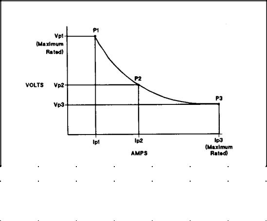
Model |
Agilent |
Agilent |
Agilent |
Agilent |
Agilent |
Agilent |
||||||
|
|
6010A |
6011A |
6012B |
6015A |
6023A |
6028A |
|||||
Vp1 |
|
200 V |
|
20 V |
|
60 V |
|
500 V |
|
20 V |
|
60 V |
Ip1 |
5 A |
50 A |
17.5 A |
2 A |
10 A |
3.3 A |
||||||
Vp2 |
|
120 V |
|
14 V |
|
40 V |
|
350 V |
|
14 V |
|
40 V |
Ip2 |
10 A |
76 A |
30 A |
3 A |
17.2 A |
6 A |
||||||
Vp3 |
|
60 V |
|
7 V |
|
20 V |
|
200 V |
|
6.7 V |
|
20 V |
Ip3 |
|
17 A |
|
120 A |
|
50 A |
|
5 A |
|
30 A |
|
10 A |
Figure 1-1. Output Characteristic Curve
General Information 15
Loading...