


 Loading...
Agilent Technologies 81480A, 81640A, 81642A, 81680A, 81689A User Manual
...Agilent 81480A and
Agilent 81680A, 81640A, 81682A, 81642A, & 81689A
Tunable Laser Modules
User’s Guide
S1

Notices
This document contains proprietary information that is protected by copyright. All rights are reserved.
No part of this document may reproduced in (including electronic storage and retrieval or translation into a foreign language) without prior agreement and written consent from Agilent Technologies Deutschland GmbH as governed by United States and international copywright laws.
Copyright 2001 by:
Agilent Technologies Deutschland GmbH Herrenberger Str. 130
71034 Böblingen
Germany
Subject Matter
The material in this document is subject to change without notice.
Agilent Technologies makes no warranty of any kind with regard to this printed material, including, but not limited to, the implied warranties of merchantability and fitness for a particular purpose.
Agilent Technologies shall not be liable for errors contained herein or for incidental or consequential damages in connection with the furnishing, performance, or use of this material.
Printing History
New editions are complete revisions of the guide reflecting alterations in the functionality of the instrument. Updates are occasionally made to the guide between editions. The date on the title page changes when an updated guide is published. To find out the current revision of the guide, or to purchase an updated guide, contact your Agilent Technologies representative.
Control Serial Number: First Edition applies directly to all instruments.
Warranty
This Agilent Technologies instrument product is warranted against defects in material and workmanship for a period of one year from date of shipment. During the warranty period, Agilent will, at its option, either repair or replace products that prove to be defective.
For warranty service or repair, this product must be returned to a service facility designated by Agilent. Buyer shall prepay shipping charges to Agilent and Agilent shall pay shipping charges to return the product to Buyer. However, Buyer shall pay all shipping charges, duties, and taxes for products returned to Agilent from another country.
Agilent warrants that its software and firmware designated by Agilent for use with an instrument will execute its programming instructions when properly installed on that instrument. Agilent does not warrant that the operation of the instrument, software, or firmware will be uninterrupted or error free.
Limitation of Warranty
The foregoing warranty shall not apply to defects resulting from improper or inadequate maintenance by Buyer, Buyer-supplied software or interfacing, unauthorized modification or misuse, operation outside of the environmental specifications for the product, or improper site preparation or maintenance.
No other warranty is expressed or implied. Agilent Technologies specifically disclaims the implied warranties of Merchantability and Fitness for a Particular Purpose.
Exclusive Remedies
The remedies provided herein are Buyer’s sole and exclusive remedies. Agilent Technologies shall not be liable for any direct, indirect, special, incidental, or consequential damages whether based on contract, tort, or any other legal theory.
Assistance
Product maintenance agreements and other customer assistance agreements are available for Agilent Technologies products. For any assistance contact your nearest Agilent Technologies Sales and Service Office.
Certification
Agilent Technologies Inc. certifies that this product met its published specifications at the time of shipment from the factory.
Agilent Technologies further certifies that its calibration measurements are traceable to the United States National Institute of Standards and Technology, NIST (formerly the United States National Bureau of Standards, NBS) to the extent allowed by the Institutes’s calibration facility, and to the calibration facilities of other International Standards Organization members.
ISO 9001 Certification
Produced to ISO 9001 international quality system standard as part of our objective of continually increasing customer satisfaction through improved process control.
Sixth Edition
81680-90014 E0101
First Edition:
E0599: May 1999
Second Edition:
E1099: October 1999
Third Edition:
E1299: December 1999
Fourth Edition:
E0300: March 2000
Fifth Edition:
E0900: September 2000
Sixth Edition:
E0101: January 2001
2 |
Agilent 81480A and 81680A, 40A, 82A, 42A, & 89A Tunable Laser Modules User’s Guide, |
|
Sixth Edition |
Safety Summary
|
Safety Summary |
|
The following general safety precautions must be observed during all |
|
phases of operation, service, and repair of this instrument. Failure to |
|
comply with these precautions or with specific warnings elsewhere in |
|
this manual violates safety standards of design, manufacture, and |
|
intended use of the instrument. Agilent Technologies Inc. assumes no |
|
liability for the customer’s failure to comply with these requirements. |
|
Before operation, review the instrument and manual, including the |
|
red safety page, for safety markings and instructions. You must follow |
|
these to ensure safe operation and to maintain the instrument in safe |
|
condition. |
W A R N I N G |
The WARNING sign denotes a hazard. It calls attention to a procedure, |
|
practice or the like, which, if not correctly performed or adhered to, |
|
could result in injury or loss of life. Do not proceed beyond a |
|
WARNING sign until the indicated conditions are fully understood and |
|
met. |
|
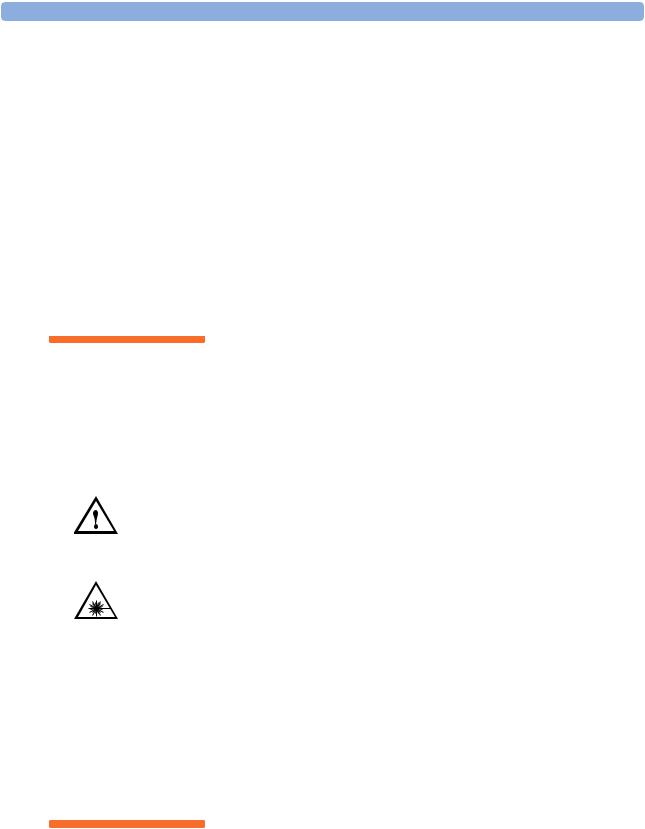
Safety Symbols |
|
The apparatus will be marked with this symbol when it is necessary |
|
for the user to refer to the instruction manual in order to protect the |
|
apparatus against damage. |
|
Hazardous laser radiation. |
|
Initial Inspection |
|
Inspect the shipping container for damage. If there is damage to the |
|
container or cushioning, keep them until you have checked the |
|
contents of the shipment for completeness and verified the instrument |
|
both mechanically and electrically. |
|
The Performance Tests give procedures for checking the operation of |
|
the instrument. If the contents are incomplete, mechanical damage or |
|
defect is apparent, or if an instrument does not pass the operator’s |
|
checks, notify the nearest Agilent Technologies Sales/Service Office. |
W A R N I N G |
To avoid hazardous electrical shock, do not perform electrical tests |
|
when there are signs of shipping damage to any portion of the outer |
|
enclosure (covers, panels, etc.). |
Agilent 81480A and 81680A, 40A, 82A, 42A, & 89A Tunable Laser Modules User’s Guide, Sixth Edition |
3 |

Safety Summary
W A R N I N G |
You MUST return instruments with malfunctioning laser modules to |
|
an Agilent Technologies Sales/Service Center for repair and |
|
calibration. |
Line Power Requirements
The Agilent 81480A, Agilent 81680A, Agilent 81640A, Agilent 81682A, Agilent 81642A, & Agilent 81689A Tunable Laser Modules operate when installed in the Agilent 8164A Lightwave Measurement System. The Agilent 81689A also operates when installed in the Agilent 8163A Lightwave Multimeter or Agilent 8166A Lightwave Multichannel System.
Operating Environment
The safety information in the Agilent 8163A Lightwave Multimeter, Agilent 8164A Lightwave Measurement System, & Agilent 8166A Lightwave Multichannel System User’s Guide summarizes the operating ranges for the Agilent 81480A, Agilent 81680A,
Agilent 81640A, Agilent 81682A, Agilent 81642A, & Agilent 81689A Tunable Laser Modules. In order for these modules to meet specifications, the operating environment must be within the limits specified for your mainframe.
|
Input/Output Signals |
C A U T I O N |
There are two BNC connectors on the front panel of the |
|
Agilent 81480A, Agilent 81680A, Agilent 81640A, Agilent 81682A, and |
|
Agilent 81642A; a BNC input connector and a BNC output connector. |
|
There is one BNC connector on the front panel of the Agilent 81689A - |
|
a BNC input connector. |
|
An absolute maximum of ±6 V can be applied as an external voltage to |
|
any BNC connector. |
|
Storage and Shipment |
|
This module can be stored or shipped at temperatures between |
|
−40°C and +70°C. Protect the module from temperature extremes that |
|
may cause condensation within it. |
4 |
Agilent 81480A and 81680A, 40A, 82A, 42A, & 89A Tunable Laser Modules User’s Guide, |
|
Sixth Edition |

Safety Summary
Initial Safety Information for Tunable Laser
Modules
The Specifications for these modules are as follows:
Table 1 Tunable Laser Modules Laser Safety Information
|
Agilent 81480A |
Agilent 81680A |
Agilent 81640A |
Agilent 81682A |
Agilent 81642A |
Agilent 81689A |
|
|
|
|
|
|
|
Laser Type |
FP-Laser |
FP-Laser |
FP-Laser |
FP-Laser |
FP-Laser |
FP-Laser |
|
InGaAsP |
InGaAsP |
InGaAsP |
InGaAsP |
InGaAsP |
InGaAsP |
Wavelength range |
1370-1480 nm |
1400-1670 nm |
1400-1670 nm |
1400-1670 nm |
1400-1670 nm |
1400-1670 nm |
Max. CW output power* |
<15 mW |
<15 mW |
<15 mW |
<15 mW |
<15 mW |
<15 mW |
Beam waist diameter |
9 m |
9 m |
9 m |
9 m |
9 m |
9 m |
Numerical aperture |
0.1 |
0.1 |
0.1 |
0.1 |
0.1 |
0.1 |
Laser Class according to |
3A |
3A |
3A |
3A |
3A |
3A |
IEC 60825-1 (1998)- International |
|
|
|
|
|
|
Max. permissible CW output |
50 mW |
50 mW |
50 mW |
50 mW |
50 mW |
50 mW |
power - IEC** |
|
|
|
|
|
|
Laser Class according to |
IIIb |
IIIb |
IIIb |
IIIb |
IIIb |
IIIb |
FDA 21 CFR 1040.10 (1995) - USA |
|
|
|
|
|
|
Max. permissible CW output |
500 mW |
500 mW |
500 mW |
500 mW |
500 mW |
500 mW |
power - FDA** |
|
|
|
|
|
|
|
|
|
|
|
|
|
* Max. CW output power is defined as the highest possible optical power that the laser source can produce at its output connector. ** Max. permissible CW output power is the highest optical power that is permitted within the appropriate laser class.
Agilent 81480A and 81680A, 40A, 82A, 42A, & 89A Tunable Laser Modules User’s Guide, Sixth Edition |
5 |
Safety Summary
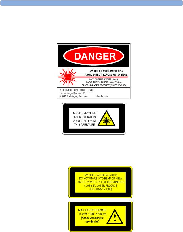
Laser Safety Labels
These laser safety warning labels are fixed on the outside of the
Agilent 8164A Lightwave Measurement System before shipment.
Figure 1 USA Safety Labels (81480A, 81680A, 81640A, 81682A, 81642A, 81689A)
These laser safety warning labels are fixed on the outside of the Agilent 8164A
Lightwave Measurement System before shipment.
Figure 2 Non-USA Safety Labels (81480A, 81680A, 81640A, 81682A, 81642A, 81689A)
6 |
Agilent 81480A and 81680A, 40A, 82A, 42A, & 89A Tunable Laser Modules User’s Guide, |
|
Sixth Edition |
Safety Summary
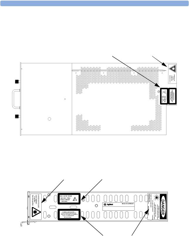
Top View
A sheet of laser safety warning labels are included with the instrument. You MUST stick the labels in the local language onto the outside of the instrument, in a position where they are clearly visible to anyone using the instrument.
See page 6 |
See page 6 |
Figure 3 Position of Safety Labels on Backloadable Tunable Laser Modules
These labels are applied in these positions to every Agilent 81480A,
Agilent 81680A, Agilent 81640A, Agilent 81682A, and Agilent 81642A
Tunable Laser Module before shipment.
See page 6 |
See page 6 |
See page 6 |
See page 6 |
Figure 4 Position of Safety Labels on Agilent 81689A Tunable Laser Module
These labels are applied in these positions to every Agilent 81689A
Tunable Laser Module before shipment.
Agilent 81480A and 81680A, 40A, 82A, 42A, & 89A Tunable Laser Modules User’s Guide, Sixth Edition |
7 |

Safety Summary
W A R N I N G |
Please pay attention to the following laser safety warnings: |
|
• Under no circumstances look into the end of an optical cable |
|
attached to the optical output when the device is operational. The |
|
laser radiation can seriously damage your eyesight. |
|
• Do not enable the laser when there is no fiber attached to the optical |
|
output connector. |
|
• The laser is enabled by pressing the gray button close to the optical |
|
output connector on the front panel of the module. The laser is on |
|
when the green LED on the front panel of the instrument is lit. |
|
• The use of optical instruments with this product will increase eye |
|
hazard. |
|
• The laser module has a built-in safety circuitry which will disable |
|
the optical output in the case of a fault condition. |
W A R N I N G |
Refer Servicing only to qualified and authorized personnel. |
8 |
Agilent 81480A and 81680A, 40A, 82A, 42A, & 89A Tunable Laser Modules User’s Guide, |
|
Sixth Edition |

The Structure of this Manual
The Structure of this Manual
This manual is divided into two categories:
•Getting Started
This section gives an introduction to the Tunable Laser modules. and aims to make these modules familiar to you:
–“Getting Started with Tunable Laser Sources” on page 21.
•Additional Information
This is supporting information of a non-operational nature. this contains information concerning accessories, specifications, and performance tests:
–“Accessories” on page 31,
–“Specifications” on page 39, and
–“Performance Tests” on page 57.
Conventions used in this manual
•Hardkeys are indicated by italics, for example, Config, or Channel.
•Softkeys are indicated by normal text enclosed in square brackets, for example, [Zoom] or [Cancel].
•Parameters are indicated by italics enclosed by square brackets, for example, [Range Mode], or [MinMax Mode].
•Menu items are indicated by italics enclosed in brackets, for example, <MinMax>, or <Continuous>.
Agilent 81480A and 81680A, 40A, 82A, 42A, & 89A Tunable Laser Modules User’s Guide, Sixth Edition |
9 |

The Structure of this Manual
10 |
Agilent 81480A and 81680A, 40A, 82A, 42A, & 89A Tunable Laser Modules User’s Guide, |
|
Sixth Edition |
Table of Contents
Table of Contents
Safety Summary |
3 |
Safety Symbols |
3 |
Initial Inspection |
3 |
Line Power Requirements |
4 |
Operating Environment |
4 |
Input/Output Signals |
4 |
Storage and Shipment |
4 |
Initial Safety Information for Tunable Laser Modules |
5 |
Laser Safety Labels |
6 |
The Structure of this Manual |
9 |
Conventions used in this manual |
9 |
Getting Started with Tunable Laser Sources |
21 |
|
|
What is a Tunable Laser ? |
23 |
Accessories
Agilent 81480A, 81680A/82A/40A/42A Tunable Laser Modules
24 |
|
Agilent 81689A Tunable Laser Module |
26 |
Optical Output |
27 |
Polarization Maintaining Fiber |
27 |
Angled and Straight Contact Connectors |
27 |
Signal Input and Output |
29 |
|
31 |
Modules and Options |
33 |
Modules |
34 |
User’s Guides |
35 |
Options |
35 |
Option 003 - Agilent 81682A, Agilent 81642A |
35 |
Option 021 - Agilent 81689A |
35 |
Option 022 - Agilent 81689A |
36 |
Option 071 - All Tunable Laser Modules |
36 |
Option 072 - All Tunable Laser Modules |
36 |
Connector Interfaces and Other Accessories |
36 |
Options 071, 021: Straight Contact Connectors |
36 |
Agilent 81480A and 81680A, 40A, 82A, 42A, & 89A Tunable Laser Modules User’s Guide, Sixth Edition |
11 |

Table of Contents
Specifications
Options 072, 022: Angled Contact Connectors |
37 |
|
39 |
|
Definition of Terms |
41 |
|
Absolute Wavelength Accuracy |
41 |
|
Effective Linewidth |
41 |
|
Linewidth |
42 |
|
Minimum Output Power |
42 |
|
Mode-Hop Free Tuning Range |
42 |
|
Modulation Extinction Ratio |
42 |
|
Modulation Frequency Range |
43 |
|
Output Power |
43 |
|
Output Isolation |
43 |
|
Peak Power |
43 |
|
Polarization Extinction Ratio |
43 |
|
Power Flatness Over Modulation |
44 |
|
Power Flatness Versus Wavelength |
44 |
|
Power Linearity |
44 |
|
Power Repeatability |
44 |
|
Power Stability |
45 |
|
Relative Intensity Noise (RIN) |
45 |
|
Relative Wavelength Accuracy |
45 |
|
Return Loss |
45 |
|
Sidemode Suppression Ratio |
46 |
|
Signal-to-Source Spontaneous Emission (SSE) Ratio |
46 |
|
Signal-to-Total-Source Spontaneous Emission |
46 |
|
Wavelength Range |
47 |
|
Wavelength Repeatability |
47 |
|
Wavelength Resolution |
47 |
|
Wavelength Stability |
47 |
|
Tunable Laser Module Specifications |
48 |
|
Supplementary Performance Characteristics |
54 |
|
Operating Modes |
54 |
|
Internal Digital Modulation 1 |
54 |
|
External Digital Modulation 1 |
54 |
|
External Analog Modulation 1 |
54 |
|
External Wavelength Locking (Agilent 81680A/40A/82A/42A) |
54 |
|
Coherence Control (Agilent 81680A/40A/82A/42A) |
54 |
|
Continuous Sweep (Agilent 81680A/40A/82A/42A) |
55 |
12 |
Agilent 81480A and 81680A, 40A, 82A, 42A, & 89A Tunable Laser Modules User’s Guide, |
|
|
Sixth Edition |
|

|
Table of Contents |
||
|
Stepped Mode (Agilent 81680A/40A/82A/42A) |
55 |
|
|
General |
55 |
|
|
Output Isolation (typ.): |
55 |
|
|
Return loss (typ.): |
55 |
|
|
Polarization Maintaining Fiber (Options 071, 072): |
55 |
|
|
Laser Class: |
55 |
|
|
Recalibration Period: |
56 |
|
|
Warm-up Time: |
56 |
|
|
Environmental |
56 |
|
|
Storage Temperature: |
56 |
|
|
Operating Temperature: |
56 |
|
|
Humidity: |
56 |
|
|
Performance Tests |
57 |
|
|
|
|
|
|
Required Test Equipment |
59 |
|
|
Test Record |
60 |
|
|
Test Failure |
60 |
|
|
Instrument Specification |
60 |
|
|
Performance Test Instructions |
61 |
|
|
General Test Setup |
61 |
|
|
Wavelength Tests |
61 |
|
|
General Settings of Wavelength Meters for all Wavelength Tests |
62 |
|
|
Wavelength Accuracy |
62 |
|
|
Relative Wavelength Accuracy |
62 |
|
|
Absolute Wavelength Accuracy |
64 |
|
|
Mode Hop Free Tuning |
64 |
|
|
Wavelength Repeatability |
65 |
|
|
Power Tests |
67 |
|
|
Calibration of the Agilent 81001FF Attenuation Filter |
67 |
|
|
Maximum Output Power |
69 |
|
|
Power Linearity |
71 |
|
|
Power Linearity - Low Power Test |
71 |
|
|
Example (Agilent 81680A Output 1) |
73 |
|
|
Power Linearity - High Power Test |
73 |
|
|
Power Linearity - Test Using Attenuation |
75 |
|
|
Power Flatness over Wavelength |
76 |
|
|
Power Flatness over Wavelength - Without Attenuation |
76 |
|
|
Power Flatness over Wavelength - Using Attenuation |
77 |
|
|
Power Stability |
79 |
|
|
Signal-to-Source Spontaneous Emission |
81 |
|
|
Signal-to-Source Spontaneous Emission Tests - High Power Outputs |
||
Agilent 81480A and 81680A, 40A, 82A, 42A, & 89A Tunable Laser Modules User’s Guide, Sixth Edition |
13 |
||

Table of Contents
|
81 |
|
|
Signal-to-Source Spontaneous Emission Tests - Low SSE Outputs |
83 |
|
Signal-to-Total-Source Spontaneous Emission |
88 |
|
Signal to Total SSE Tests - Low SSE Outputs |
89 |
|
Optional Test |
95 |
|
Signal to Total SSE Tests - High Power Outputs |
95 |
|
Test Record |
99 |
|
Agilent 81480A Performance Test |
99 |
|
Test Equipment Used |
100 |
|
Relative Wavelength Accuracy |
101 |
|
Mode Hop Free Tuning |
103 |
|
Wavelength Repeatability |
104 |
|
Maximum Power Test |
105 |
|
Power Linearity Output 1, Low SSE |
106 |
|
Power Linearity Output 2, High Power Upper Power Levels |
106 |
|
Power Linearity Output 2, High Power by attenuator |
107 |
|
Power Flatness |
108 |
|
Power Stability |
109 |
|
Signal-to-Source Spontaneous Emission - 81480A Output 2, High |
|
|
Power |
109 |
|
Signal-to-Source Spontaneous Emission - 81480A Output 1, Low SSE |
|
|
110 |
|
|
Signal-to-Total-Source Spontaneous Emission - 81480A Output 1, Low |
|
|
SSE |
111 |
|
Optional Test: Signal-to-Total-Source Spontaneous Emission - 81480A |
|
|
Output 2, High Power |
111 |
|
Agilent 81680A Performance Test |
113 |
|
Test Equipment Used |
114 |
|
Relative Wavelength Accuracy |
115 |
|
Mode Hop Free Tuning |
117 |
|
Wavelength Repeatability |
118 |
|
Maximum Power Test |
119 |
|
Power Linearity Output 1, Low SSE |
120 |
|
Power Linearity Output 2, High Power Upper Power Levels |
120 |
|
Power Linearity Output 2, High Power by attenuator |
121 |
|
Power Flatness |
122 |
|
Power Stability |
123 |
|
Signal-to-Source Spontaneous Emission - 81680A Output 2, High |
|
|
Power |
123 |
|
Signal-to-Source Spontaneous Emission - 81680A Output 1, Low SSE |
|
|
124 |
|
|
Signal-to-Total-Source Spontaneous Emission - 81680A Output 1, Low |
|
|
SSE |
125 |
|
Optional Test: Signal-to-Total-Source Spontaneous Emission - 81680A |
|
14 |
Agilent 81480A and 81680A, 40A, 82A, 42A, & 89A Tunable Laser Modules User’s Guide, |
|
|
Sixth Edition |
|

|
Table of Contents |
|
Output 2, High Power |
|
125 |
Agilent 81640A Performance Test |
|
127 |
Test Equipment Used |
|
128 |
Relative Wavelength Accuracy |
|
129 |
Relative Wavelength Accuracy Summary of all Repetitions |
130 |
|
Relative Wavelength Accuracy Result |
|
130 |
Absolute Wavelength Accuracy Result |
|
130 |
Mode Hop Free Tuning |
|
131 |
Wavelength Repeatability |
|
132 |
Maximum Power Test |
|
133 |
Power Linearity |
Output 1, Low SSE134 |
|
Power Linearity Output 2, High Power Upper Power Levels |
134 |
|
Power Linearity Output 2, High Power by Attenuator |
135 |
|
Power Flatness |
|
136 |
Power Stability |
|
137 |
Signal-to-Source Spontaneous Emission - 81640A Output 2, High |
|
|
Power |
|
137 |
Signal-to-Source Spontaneous Emission - 81640A Output 1, Low SSE |
||
138 |
|
|
Signal-to-Total-Source Spontaneous Emission - 81640A Output 1, Low |
||
SSE |
|
139 |
Optional Test - Signal-to-Total-Source Spontaneous Emission - 81640A |
||
Output 2, High Power |
|
139 |
Agilent 81682A Performance Test |
|
141 |
Test Equipment Used |
|
142 |
Relative Wavelength Accuracy |
|
143 |
Mode Hop Free Tuning |
|
145 |
Wavelength Repeatability |
|
146 |
Maximum Power Test |
|
147 |
Power Linearity - 81682A |
|
147 |
Power Linearity 81682A #003 Upper Power Levels |
148 |
|
Power Linearity 81682A #003 by Attenuator |
|
149 |
Power Flatness |
|
150 |
Power Stability |
|
151 |
Signal-to-Source Spontaneous Emission - 81682A |
151 |
|
Optional Test: Signal-to-Total-Source Spontaneous Emission - 81682A |
||
152 |
|
|
Agilent 81642A Performance Test |
|
153 |
Test Equipment Used |
|
154 |
Relative Wavelength Accuracy |
|
155 |
Mode Hop Free Tuning |
|
157 |
Wavelength Repeatability |
|
158 |
Maximum Power Test |
|
159 |
Power Linearity - 81642A |
|
159 |
Power Linearity 81642A #003 Upper Power Levels |
160 |
|
Agilent 81480A and 81680A, 40A, 82A, 42A, & 89A Tunable Laser Modules User’s Guide, Sixth Edition |
|
15 |

Table of Contents
|
Power Linearity 81642A #003 by Attenuator |
161 |
|
Power Flatness |
162 |
|
Power Stability |
163 |
|
Signal-to-Source Spontaneous Emission - 81642A |
163 |
|
Optional Test: Signal-to-Total-Source Spontaneous Emission - 81642A |
|
|
164 |
|
|
Agilent 81689A Performance Test |
165 |
|
Test Equipment Used |
166 |
|
Relative Wavelength Accuracy |
167 |
|
Wavelength Repeatability |
168 |
|
Maximum Power Test |
169 |
|
Power Linearity |
169 |
|
Power Flatness |
170 |
|
Power Stability |
170 |
|
Signal-to-Source Spontaneous Emission |
170 |
|
Cleaning Information |
171 |
|
|
|
|
Safety Precautions |
173 |
|
Why is it important to clean optical devices? |
173 |
|
What do I need for proper cleaning? |
174 |
|
Standard Cleaning Equipment |
174 |
|
Dust and shutter caps |
174 |
|
Isopropyl alcohol |
175 |
|
Cotton swabs |
175 |
|
Soft tissues |
176 |
|
Pipe cleaner |
176 |
|
Compressed air |
176 |
|
Additional Cleaning Equipment |
177 |
|
Microscope with a magnification range about 50X up to 300X |
177 |
|
Ultrasonic bath |
177 |
|
Warm water and liquid soap |
178 |
|
Premoistened cleaning wipes |
178 |
|
Polymer film |
178 |
|
Infrared Sensor Card |
178 |
|
Preserving Connectors |
179 |
|
Cleaning Instrument Housings |
179 |
|
Which Cleaning Procedure should I use ? |
180 |
|
How to clean connectors |
180 |
|
How to clean connector adapters |
181 |
|
How to clean connector interfaces |
182 |
16 |
Agilent 81480A and 81680A, 40A, 82A, 42A, & 89A Tunable Laser Modules User’s Guide, |
|
|
Sixth Edition |
|

Table of Contents
How to clean bare fiber adapters |
183 |
How to clean lenses |
184 |
How to clean instruments with a fixed connector interface
184
How to clean instruments with an optical glass plate 185 How to clean instruments with a physical contact interface
185
How to clean instruments with a recessed lens interface
186
How to clean optical devices which are sensitive to |
|
mechanical stress and pressure |
187 |
How to clean metal filters or attenuator gratings |
188 |
Additional Cleaning Information |
189 |
How to clean bare fiber ends |
189 |
How to clean large area lenses and mirrors |
189 |
Other Cleaning Hints |
191 |
Agilent 81480A and 81680A, 40A, 82A, 42A, & 89A Tunable Laser Modules User’s Guide, Sixth Edition |
17 |

Table of Contents
18 |
Agilent 81480A and 81680A, 40A, 82A, 42A, & 89A Tunable Laser Modules User’s Guide, |
|
Sixth Edition |

List of Figures
List of Figures
Figure 1 |
USA Safety Labels (81480A, 81680A, 81640A, 81682A, 81642A, 81689A) . . |
6 |
Figure 2 |
Non-USA Safety Labels (81480A, 81680A, 81640A, 81682A, 81642A, 81689A) |
6 |
Figure 3 |
Position of Safety Labels on Backloadable Tunable Laser Modules . . . |
7 |
Figure 4 |
Position of Safety Labels on Agilent 81689A Tunable Laser Module . . . |
7 |
Figure 5 |
Agilent 81480A Tunable Laser Module (straight contact connectors) . . . |
24 |
Figure 6 |
Agilent 81680A Tunable Laser Module (straight contact connectors) . . . |
24 |
Figure 7 |
Agilent 81682A Tunable Laser Module (straight contact connector) . . . |
24 |
Figure 8 |
Agilent 81640A Tunable Laser Module (straight contact connectors) . . . |
24 |
Figure 9 |
Agilent 81642A Tunable Laser Module (straight contact connectors) . . . |
24 |
Figure 10 |
Agilent 81689A Tunable Laser Module . . . . . . . . . . |
26 |
Figure 11 |
PMF Output Connector . . . . . . . . . . . . . . |
27 |
Figure 12 |
Angled and Straight Contact Connector Symbols . . . . . . . . |
28 |
Figure 13 |
Agilent 81682A Tunable Laser Module (angled contact connector) . . . |
28 |
Figure 14 |
Mainframes, Tunable Laser Modules, and Options . . . . . . . |
33 |
Figure 15 |
Options 021, 071: Single-mode fiber/PMF with Straight Contact Connectors . |
37 |
Figure 16 |
Options 022, 072: Single-mode fiber/PMF with Angled Contact Connectors . |
38 |
Figure 17 |
Test Setup for Wavelength Tests . . . . . . . . . . . . |
61 |
Figure 18 |
Calibration of the Agilent 81001FF Attenuation Filter, Reference Setup . . |
67 |
Figure 19 |
Test Setup for Calibrating the Agilent 81001FF Attenuation Filter . . . . |
68 |
Figure 20 |
Test Setup for the Maximum Output Power Tests. . . . . . . . |
69 |
Figure 21 |
Test Setup for Low Power Linearity Tests. . . . . . . . . . |
71 |
Figure 22 |
Test Setup for the Source Spontaneous Emission Test - High Power Outputs . |
81 |
Figure 23 |
Transmission Characteristic of Fiber Bragg Grating . . . . . . . |
84 |
Figure 24 |
Signal-to-Spectral SSE Measurement . . . . . . . . . . |
84 |
Figure 25 |
Test Setup for Source Spontaneous Emission Test . . . . . . . |
85 |
Agilent 81480A and 81680A, 40A, 82A, 42A, & 89A Tunable Laser Modules User’s Guide, Sixth Edition |
19 |

List of Figures
20 |
Agilent 81480A and 81680A, 40A, 82A, 42A, & 89A Tunable Laser Modules User’s Guide, |
|
Sixth Edition |
Getting Started with Tunable Laser Sources
Agilent 81480A and 81680A, 40A, 82A, 42A, & 89A Tunable Laser Modules User’s Guide, Sixth Edition |
21 |

Getting Started with Tunable Laser Sources
This chapter describes the Agilent 81480A, Agilent 81680A,
Agilent 81640A, Agilent 81682A, Agilent 81642A, and Agilent 81689A Tunable Laser modules.
22 |
Agilent 81480A and 81680A, 40A, 82A, 42A, & 89A Tunable Laser Modules User’s Guide, |
|
Sixth Edition |

What is a Tunable Laser ?
Getting Started with Tunable Laser Sources
What is a Tunable Laser ?
A Tunable Laser is a laser source for which the wavelength can be varied through a specified range. The Agilent Technologies range of Tunable Laser modules also allow you to set the output power, and to choose between continuous wave or modulated power.
Agilent 81480A and 81680A, 40A, 82A, 42A, & 89A Tunable Laser Modules User’s Guide, Sixth Edition |
23 |

Getting Started with Tunable Laser Sources |
What is a Tunable Laser ? |
Agilent 81480A, 81680A/82A/40A/42A
Tunable Laser Modules
Figure 5 Agilent 81480A Tunable Laser Module (straight contact connectors)
Figure 6 Agilent 81680A Tunable Laser Module (straight contact connectors)
Figure 7 Agilent 81682A Tunable Laser Module (straight contact connector)
Figure 8 Agilent 81640A Tunable Laser Module (straight contact connectors)
|
Figure 9 Agilent 81642A Tunable Laser Module (straight contact connectors) |
24 |
Agilent 81480A and 81680A, 40A, 82A, 42A, & 89A Tunable Laser Modules User’s Guide, |
|
Sixth Edition |

What is a Tunable Laser ?
Getting Started with Tunable Laser Sources
The Agilent 81480A and 81680A/82A/40A/42A Tunable Laser modules are back-loadable modules. To fit these modules into the Agilent 8164A mainframe see “How to Fit and Remove Modules” in the Agilent 8163A Lightwave Multimeter, Agilent 8164A, Lightwave Measurement System, & Agilent 8166A Lightwave Multichannel SystemUser’s Guide.
The Agilent 81480A and 81680A/82A/40A/42A Tunable Laser modules have a built-in wavelength control loop to ensure high wavelength accuracy. As these modules are all mode-hop free tunable with continuous output power, they qualify for the test of the most critical dense-Wavelength Division Multiplexer (dWDM) components.
The Agilent 81480A and Agilent 81640A/80A Tunable Laser modules are equipped with two optical outputs:
•Output 1, the Low SSE output, delivers a signal with ultra-low source spontaneous emission (SSE). It enables accurate crosstalk measurement of DWDM components with many channels at narrow spacing. You can characterize steep notch filters such as Fiber Bragg Gratings by using this output and a power sensor module.
•Output 2, the High Power output, delivers a signal with high optical power. You can adjust the signal by more than 60 dB by using the inbuilt optical attenuator.
The Agilent 81682A/42A Tunable Laser module delivers a signal with high optical power. If you choose Option 003, you can adjust the signal by more than 60 dB by using the in-built optical attenuator.
Agilent 81480A and 81680A, 40A, 82A, 42A, & 89A Tunable Laser Modules User’s Guide, Sixth Edition |
25 |
Getting Started with Tunable Laser Sources |
What is a Tunable Laser ? |
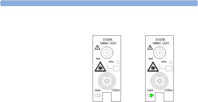
Agilent 81689A Tunable Laser Module
Agilent 81689A with |
Agilent 81689A with |
Straight Contact Connector |
Angled Contact Connector |
Figure 10 Agilent 81689A Tunable Laser Module
The Agilent 81689A Tunable Laser module is a front-loadable module. To insert this module into the Agilent 8163A Lightwave Multimeter, Agilent 8164A Lightwave Measurement System or Agilent 8166A Lightwave Multichannel System see “How to Fit and Remove Modules” in the Agilent 8163A Lightwave Multimeter, Agilent 8164A Lightwave Measurement System, & Agilent 8166A Lightwave Multichannel System User’s Guide.
You can use the Agilent 81689A Tunable Laser module to set up a realistic multi-channel test-bed for DWDM transmission systems. Its continuous, mode-hop free tuning makes it quick and easy to set even the most complex configurations to the target wavelengths and power levels.
The Agilent 8163A Lightwave Multimeter, a Power Sensor module,and a Agilent 81689A Tunable Laser module together represent a smart loss-test set with selectable wavelength.
26 |
Agilent 81480A and 81680A, 40A, 82A, 42A, & 89A Tunable Laser Modules User’s Guide, |
|
Sixth Edition |

Optical Output |
Getting Started with Tunable Laser Sources |
Optical Output
Polarization Maintaining Fiber
If you have an instrument with a polarization maintaining fiber (PMF), the PMF is aligned to maintain the state of polarization.
The fiber is of Panda type, with TE mode in the slow axis in line with the connector key. A well defined state of polarization ensures constant measurement conditions.
The Agilent 81480A and 81680A/40A/82A/42A Tunable Laser modules are equipped with PMF outputs as standard.
For the Agilent 81689A Tunable Laser module, PMF output is available as an option.
|
|
|
|
|
|
|
|
|
|
|
|
E |
|||||||||
|
|
|
|
|
|
|
|
|
|
|
|
|
|
|
|
|
|
|
Connector Key |
||
|
|
|
|
|
|
|
|
|
|
|
|
|
|
|
|
|
|
|
Fiber Cladding |
||
|
|
|
|
|
|
|
|
|
|
|
|
|
|
|
|
|
|
|
|||
|
|
|
|
|
|
|
|
|
|
|
|
|
|
|
|
|
|
|
|||
|
|
|
|
|
|
|
|
|
|
|
|
|
|
|
|
|
|
|
|
|
|
|
|
|
|
|
|
|
|
|
|
|
|
|
|
|
|
|
|
|
|
|
|
|
|
|
|
|
|
|
|
|
|
|
|
|
|
|
|
|
|
|
H |
||
|
|
|
|
|
|
|
|
|
|
|
|||||||||||
|
|
|
|
|
|
|
|
|
|
|
|
|
|
|
|
|
|
|
Fiber Core |
||
|
|
|
|
|
|
|
|
|
|
|
|
|
|
|
|
|
|
|
|||
|
|
|
|
|
|
|
|
|
|
|
|
|
|
|
|
|
|
|
|||
|
|
|
|
|
|
|
|
|
|
|
|||||||||||
Stress Rods |
|
|
|
|
|
|
|
|
|
|
|
|
|
|
|
(8- m Diameter) |
|||||
|
|
|
|
|
|
|
|
|
|||||||||||||
|
|
|
|
|
|
|
|
|
|
|
|
|
|
|
|
|
|
|
|
|
|
|
|
|
|
|
|
|
|
|
|
|
|
|
|
|
|
|
|
|
|
|
|
|
|
Slow Axis (Polarization Axis) |
|||||||||||||||||||
|
|
|
|
|
Not to Scale |
||||||||||||||||
Figure 11 PMF Output Connector
Angled and Straight Contact Connectors
Angled contact connectors help you to control return loss. With angled fiber endfaces, reflected light tends to reflect into the cladding, reducing the amount of light that reflects back to the source.
The Agilent 81480 and 81680A/40A/82A/42A/89A Tunable Laser modules can have the following connector interface options:
•Option 071, Polarization-maintaining fiber straight contact connectors, or
•Option 072, Polarization-maintaining fiber angled contact connectors.
Agilent 81480A and 81680A, 40A, 82A, 42A, & 89A Tunable Laser Modules User’s Guide, Sixth Edition |
27 |
Getting Started with Tunable Laser Sources |
Optical Output |
Two additional connector interface options are available for the
Agilent 81689A Tunable Laser module:
• Option 021, Standard single-mode fiber straight contact connectors,
or
|
• Option 022, Standard single-mode fiber angled contact connectors. |
C A U TI O N |
If the contact connector on your instrument is angled, you can only |
|
use cables with angled connectors with the instrument. |
Angled Contact |
Straight Contact |
Connector Symbol |
Connector Symbol |
Figure 12 Angled and Straight Contact Connector Symbols
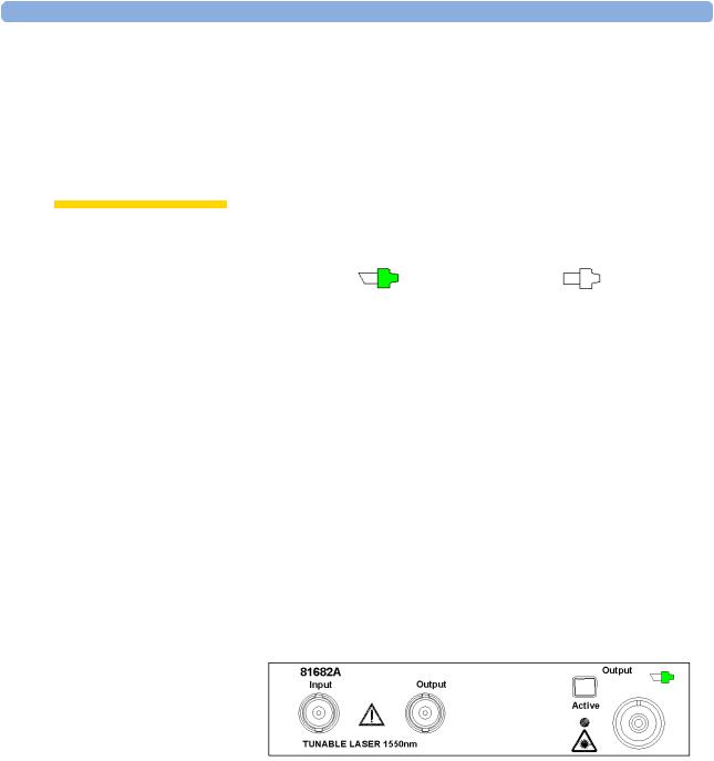
Figure 12 shows the symbols that tell you whether the contact connector of your Tunable Laser module is angled or straight. The angled contact connector symbol is colored green.
Figure 7 and Figure 13 show the front panel of the Agilent 81682A Tunable Laser module with straight and angled contact connectors respectively.
You should connect straight contact fiber end connectors with neutral sleeves to straight contact connectors and connect angled contact fiber end connectors with green sleeves to angled contact connectors.
N O TE You cannot connect angled non-contact fiber end connectors with orange sleeves directly to the instrument.
Figure 13 Agilent 81682A Tunable Laser Module (angled contact connector)
See “Accessories” on page 31 for further details on connector interfaces and accessories.
28 |
Agilent 81480A and 81680A, 40A, 82A, 42A, & 89A Tunable Laser Modules User’s Guide, |
|
Sixth Edition |

Signal Input and Output |
Getting Started with Tunable Laser Sources |
Signal Input and Output
CA U TI O N |
There are two BNC connectors on the front panel of the |
|
Agilent 81480A, Agilent 81680A, Agilent 81680A, Agilent 81640A, |
|
Agilent 81682A, and Agilent 81642A - a BNC input connector and a |
|
BNC output connector. |
|
There is one BNC connector on the front panel of the Agilent 81689A - |
|
a BNC input connector. |
|
An absolute maximum of ±6 V can be applied as an external voltage to |
|
any BNC connector. |
Agilent 81480A and 81680A, 40A, 82A, 42A, & 89A Tunable Laser Modules User’s Guide, Sixth Edition |
29 |

Getting Started with Tunable Laser Sources |
Signal Input and Output |
30 |
Agilent 81480A and 81680A, 40A, 82A, 42A, & 89A Tunable Laser Modules User’s Guide, |
|
Sixth Edition |
Loading...