


 Loading...
Agilent Technologies
Low-Profile
Modular Power System
Series N6700
User’s Guide


 A
A

Legal Notices
© Agilent Technologies, Inc. 2006-2008
No part of this document may be photocopied, reproduced, or translated to another language without the prior agreement and written consent of Agilent Technologies, Inc. as governed by United States and international copyright laws.
Warranty
The material contained in this document is provided “as is,” and is subject to being changed, without notice, in future editions. Further, to the maximum extent permitted by applicable law, Agilent disclaims all warranties, either express or implied, with regard to this manual and any information contained herein, including but not limited to the implied warranties of merchantability and fitness for a particular purpose. Agilent shall not be liable for errors or for incidental or consequential damages in connection with the furnishing, use, or performance of this document or of any information contained herein. Should Agilent and the user have a separate written agreement with warranty terms covering the material in this document that conflict with these terms, the warranty terms in the separate agreement shall control.
Manual Editions
Manual Part Number: 5969-2937 Fourth Edition, January, 2008 Printed in Malaysia.
Reprints of this manual containing minor corrections and updates may have the same printing date. Revised editions are identified by a new printing date.
Waste Electrical and Electronic Equipment (WEEE) Directive 2002/96/EC
This product complies with the WEEE Directive 2002/96/EC) marketing requirement. The affixed product label (see below) indicates that you must not discard this electrical/electronic product in domestic household waste.
Product Category: With reference to the equipment types in the WEEE directive Annex 1, this product is classified as “Monitoring and Control instrumentation” product.
Do not dispose in domestic household waste.
To return unwanted products, contact our local Agilent office, or see www.agilent.com/environment/product for more information.
Certification
Agilent Technologies certifies that this product met its published specifications at time of shipment from the factory.
Agilent Technologies further certifies that its calibration measurements are traceable to the United States National Institute of Standards and Technology, to the extent allowed by the Institute's calibration facility, and to the calibration facilities of other International Standards Organization members.
Exclusive Remedies
THE REMEDIES PROVIDED HEREIN ARE THE CUSTOMER'S SOLE AND EXCLUSIVE REMEDIES. AGILENT TECHNOLOGIES SHALL NOT BE LIABLE FOR ANY DIRECT, INDIRECT, SPECIAL, INCIDENTAL, OR CONSEQUENTIAL DAMAGES, WHETHER BASED ON CONTRACT, TORT, OR ANY OTHER LEGAL THEORY.
Assistance
This product comes with the standard product warranty. Warranty options, extended support contacts, product maintenance agreements and customer assistance agreements are also available. Contact your nearest Agilent Technologies Sales and Service office for further information on Agilent Technologies' full line of Support Programs.
Technologies Licenses
The hardware and or software described in this document are furnished under a license and may be used or copied only in accordance with the terms of such license.
U.S. Government Restricted Rights
Software and technical data rights granted to the federal government include only those rights customarily provided to end user customers. Agilent provides this customary commercial license in Software and technical data pursuant to FAR 12.211 (Technical Data) and 12.212 (Computer Software) and, for the Department of Defense, DFARS 252.2277015 (Technical Data – Commercial Items) and DFARS 227.7202-3 (Rights in Commercial Computer Software or Computer Software Documentation).
Trademarks
Microsoft and Windows are U.S. registered trademarks of Microsoft Corporation.
2 |
Series N6700 User’s Guide |
Safety Notices
The following general safety precautions must be observed during all phases of operation of this instrument. Failure to comply with these precautions or with specific warnings or instructions elsewhere in this manual violates safety standards of design, manufacture, and intended use of the instrument. Agilent Technologies assumes no liability for the customer's failure to comply with these requirements.
General
Do not use this product in any manner not specified by the manufacturer. The protective features of this product may be impaired if it is used in a manner not specified in the operation instructions.
Before Applying Power
Verify that all safety precautions are taken. Make all connections to the unit before applying power. Note the instrument's external markings described under "Safety Symbols"
Ground the Instrument
This product is a Safety Class 1 instrument (provided with a protective earth terminal). To minimize shock hazard, the instrument chassis and cover must be connected to an electrical ground. The instrument must be connected to the AC power mains through a grounded power cable, with the ground wire firmly connected to an electrical ground (safety ground) at the power outlet. Any interruption of the protective (grounding) conductor or disconnection of the protective earth terminal will cause a potential shock hazard that could result in personal injury.
Fuses
The instrument contains an internal fuse, which is not customer accessible.
Do Not Operate in an Explosive Atmosphere
Do not operate the instrument in the presence of flammable gases or fumes.
Do Not Remove the Instrument Cover
Only qualified, service-trained personnel who are aware of the hazards involved should remove instrument covers. Always disconnect the power cable and any external circuits before removing the instrument cover.
Do Not Modify the Instrument
Do not install substitute parts or perform any unauthorized modification to the product. Return the product to an Agilent Sales and Service Office for service and repair to ensure that safety features are maintained.
In Case of Damage
Instruments that appear damaged or defective should be made inoperative and secured against unintended operation until they can be repaired by qualified service personnel.
CAUTION
A CAUTION notice denotes a hazard. It calls attention to an operating procedure, practice, or the like that, if not correctly performed or adhered to, could result in damage to the product or loss of important data. Do not proceed beyond a CAUTION notice until the indicated conditions are fully understood and met.
WARNING
A WARNING notice denotes a hazard. It calls attention to an operating procedure, practice, or the like that, if not correctly performed or adhered to, could result in personal injury or death. Do not proceed beyond a WARNING notice until the indicated conditions are fully understood and met.
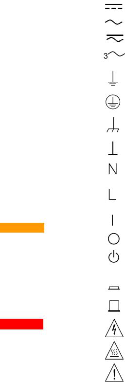
Safety Symbols
Direct current
Alternating current
Both direct and alternating current
Three phase alternating current
Earth (ground) terminal
Protective earth ground terminal.
Frame or chassis terminal
Terminal is at earth potential.
Neutral conductor on permanently installed equipment
Line conductor on permanently installed equipment.
On supply
Off supply
Standby supply. Unit is not completely disconnected from AC mains when switch is off
In position of a bi-stable push switch
Out position of a bi-stable push switch
Caution, risk of electric shock
Caution, hot surface
Caution, refer to accompanying description
Series N6700 User’s Guide |
3 |

In this Book
Specific chapters in this manual contain the following information:
Quick Reference – Chapter 1 is a quick reference section that helps you quickly become familiar with your Agilent N6700 Modular Power System. It describes the differences between the various modules in the power system.
Installation – Chapter 2 describes how to install your power system. It describes how to connect various loads to the output. It discusses remote sensing as well as parallel and series operation.
Getting Started – Chapter 3 describes how to set the voltage, current, over-voltage protection, and turn on the output. It also describes how to configure the remote interface.
Operating the Power System – Chapter 4 describes how to use the advanced features of the power system using the front panel menus and the corresponding SCPI commands.
Specifications – Appendix A describes specifications and supplemental characteristics.
Using the Digital Port – Appendix B describes how to configure and use the digital port on the back of the instrument.
Power Allocation – Appendix C describes the power allocation function, which applies to power system in which the combined ratings of the power modules exceed the power rating of the mainframe.
Output On/Off Synchronization – Appendix D discusses output on/off synchronization, which lets you accurately synchronize output turn-on sequences across multiple mainframes.
For complete details on the SCPI (Standard Commands for
Programmable Instruments) commands, refer to the Programmer’s
Reference Help file included on the Agilent N6700 Product Reference
CD. This CD-ROM is shipped along with your instrument.
NOTE You can contact Agilent Technologies at one of the following telephone numbers for warranty, service, or technical support information.
In the United States: (800) 829-4444 In Europe: 31 20 547 2111
In Japan: 0120-421-345
Or use our Web link for information on contacting Agilent in your country or specific location: www.agilent.com/find/assist
Or contact your Agilent Technologies Representative.
The web contains the most up to date version of the manual. Go to
http://www.agilent.com/find/N6700 to get the latest version of the manual.
4 |
Series N6700 User’s Guide |

Contents
1 - Quick Reference............................................................................................................................... |
7 |
The Agilent N6700 Modular Power System – At a Glance.......................... |
8 |
The Front Panel - At a Glance......................................................................... |
10 |
The Rear Panel – At a Glance......................................................................... |
10 |
Front Panel Display – At a Glance ................................................................. |
11 |
Front Panel Keys – At a Glance...................................................................... |
12 |
Front Panel Menu Reference .......................................................................... |
13 |
SCPI Command Summary................................................................................ |
15 |
2 - Installation...................................................................................................................................... |
19 |
General Information.......................................................................................... |
20 |
Inspecting the Unit ........................................................................................... |
21 |
Installing the Unit.............................................................................................. |
21 |
Connecting the Line Cord ................................................................................ |
24 |
Connecting the Outputs................................................................................... |
25 |
Remote Sense Connections ............................................................................ |
29 |
Parallel Connections......................................................................................... |
30 |
Series Connections........................................................................................... |
32 |
3 - Getting Started............................................................................................................................... |
35 |
Turning the Unit On .......................................................................................... |
36 |
Selecting an Output Channel .......................................................................... |
36 |
Entering an Output Voltage Setting ............................................................... |
36 |
Entering a Current Limit Setting..................................................................... |
37 |
Enabling the Output.......................................................................................... |
37 |
Using the Front Panel Menu ........................................................................... |
38 |
Connecting to the Interfaces .......................................................................... |
40 |
4 - Operating the Power System ....................................................................................................... |
51 |
Programming the Output ................................................................................. |
52 |
Synchronizing Output Steps............................................................................ |
55 |
Making Measurements.................................................................................... |
58 |
Using the Protection Functions ...................................................................... |
59 |
System-Related Operations............................................................................. |
61 |
Programming High-Speed Test Extensions .................................................. |
65 |
Series N6700 User’s Guide |
5 |
Appendix A - Specifications .............................................................................................................. |
75 |
Agilent Models N6751A/N6752A, N6753A/N6754A, N6761A/N6762A 76 |
|
Agilent Models N6731B - N6736B and N6741B - N6746B........................ |
82 |
Agilent Models N6773A - N6776A................................................................. |
84 |
Agilent N6700B, N6701A, N6702A MPS Mainframes................................ |
86 |
Appendix B - Using the Digital Port.................................................................................................. |
89 |
Digital Control Port ........................................................................................... |
90 |
Configuring the Digital Control Port............................................................... |
91 |
Appendix C - Power Allocation ......................................................................................................... |
95 |
Power Limit Operation ..................................................................................... |
96 |
Module Power Allocation ................................................................................ |
97 |
Apendix D - Output On/Off Synchronization ................................................................................... |
99 |
Synchronizing Output Turn-on Delays......................................................... |
100 |
Synchronizing Multiple Mainframes............................................................ |
103 |
Operation .......................................................................................................... |
104 |
Index................................................................................................................................................... |
105 |
6 |
Series N6700 User’s Guide |

1
Quick Reference
The Agilent N6700 Modular Power System – At a Glance |
.......................... 8 |
The Front Panel - At a Glance......................................................................... |
10 |
The Rear Panel – At a Glance......................................................................... |
10 |
Front Panel Display – At a Glance ................................................................. |
11 |
Front Panel Keys – At a Glance...................................................................... |
12 |
Front Panel Menu Reference .......................................................................... |
13 |
SCPI Command Summary................................................................................ |
15 |
|
This chapter concisely describes the operation of the Agilent N6700 |
|
Modular Power System (MPS). |
|
This chapter does not describe every operating feature in detail. It is |
|
simply a quick reference guide to quickly become familiar with the |
|
essential operating features of the power system. |
|
For complete details on the SCPI (Standard Commands for |
|
Programmable Instruments) commands, refer to the Programmer’s |
|
Reference Help file included on the Agilent N6700 Product Reference |
|
CD. This CD-ROM is shipped along with your instrument. |
|
Unless otherwise noted, the Agilent N6700 Modular Power System will also be |
NOTE |
|
|
referred to as “MPS” and “power system” throughout this manual. |
|
|
Series N6700 User’s Guide |
7 |
1 Quick Reference
The Agilent N6700 Modular Power System – At a Glance
The Agilent N6700 Modular Power System is a configurable, one rackunit (1U) platform that lets you mix and match power modules to create a power system optimized for your test system requirements.
Agilent N6700–N6702 MPS mainframes are available in power levels of 400 W, 600 W, and 1,200 W. Up to four power modules can be installed in each mainframe. Power modules come in power levels of 50 W, 100 W, and 300 W, have various voltage and current combinations, and provide the following performance features:
The N673xB, N674xB, and N677xA DC Power Modules provide programmable voltage and current, measurement, and protection features, making these economical modules suitable for powering the device-under-test or system resources such as fixture controls.
The N675xA High-Performance, Autoranging DC Power Modules provide low noise, high accuracy, fast programming times, and advanced programming and measurement capabilities to speed test throughput.
The N676xA Precision DC Power Modules provide precise control and measurements in the milliand micro-ampere region with the ability to simultaneously digitize voltage and current and capture those measurements into an oscilloscope-like data buffer.
The output and system features are described in the following sections. Not all output features are available on every power module. The “Model Differences” section describes the features that apply only to specific power modules.
Output Features
Programmable voltage Full programming capability is provided for the entire range of output
and current voltage and current. Outputs can operate as either constant voltage (CV) or constant current (CC) sources.
Fast command processing Command processing time of less than 1 millisecond per command.
Fast up/down |
1.5 millisecond response time from 10% to 90% of the output rating for |
programming |
autoranging and precision power modules. Refer to Appendix A for details. |
Fast transient response |
Transient response is less than 100 microseconds for autoranging and |
|
precision power modules. Refer to Appendix A for details. |
Low output noise |
Output noise is 4.5 mV peak-to-peak for autoranging and precision power |
|
modules, which is comparable to linear supplies. Refer to Appendix A for |
|
details. |
Autoranging capability |
Autoranging produces the maximum rated power over a wide and |
|
continuous range of voltage and current settings for autoranging and |
|
precision power modules. Refer to Appendix A for details. |
8 |
Series N6700 User’s Guide |
Quick Reference 1
Output On/Off sequencing A turn-on/turn-off delay capability for each output allows output on/off sequencing.
Remote voltage sensing |
Two remote sensing terminals are provided for each output. When shipped, |
|
the remote sense jumpers are included in a separate bag. See Chapter 2. |
Voltage and current |
All power modules can measure their own output voltage and current. |
measurements |
|
Voltage, current, and |
Each output has over-voltage, over-current, and over-temperature |
temperature protection |
protection. Over-voltage and over-current protection are programmable. |
|
When activated, the protection circuits cause the voltage to go to zero, the |
|
output to be disabled, and the protection status to be reported. |
System Features
SCPI language |
The instrument is compatible with the Standard Commands for |
|
Programmable Instruments (SCPI). |
Choice of three interfaces GPIB (IEEE-488), LAN, and USB remote programming interfaces are built in.
Front panel I/O setup Menus let you set up GPIB and LAN parameters from the front panel. Refer to Chapter 3 for details.
Built-in Web server |
A built-in Web server lets you control the instrument directly from an |
|
internet browser on your computer. Refer to Chapter 3 for details. |
Real-time status |
The front panel indicates the status of each output. It also indicates when |
information |
a protection shut-down has occurred. |
Module identification |
Each module has identifying data stored in non-volatile memory. |
|
Information includes model number, serial number, and options. This |
|
information can be displayed on the front panel. |
Model Differences
Feature |
|
DC Power Modules |
Autoranging Modules |
Precision Modules |
||||
|
N6731B - N6741B - N6773A - |
N6751A |
N6752A |
N6753A |
N6761A |
N6762A |
||
|
N6736B |
N6746B |
N6776A |
|
|
N6754A |
|
|
Output power rating |
50 W |
100 W |
300 W |
50 W |
100 W |
300 W |
50 W |
100 W |
Autoranging output capability |
NO |
NO |
NO |
YES |
YES |
YES |
YES |
YES |
Precision output and measurement capability |
NO |
NO |
NO |
NO |
NO |
NO |
YES |
YES |
Low voltage output and measurement range |
NO |
NO |
NO |
NO |
NO |
NO |
YES |
YES |
Low current output and measurement range |
NO |
NO |
NO |
NO |
NO |
NO |
YES |
YES |
Simultaneous voltage and current measurement |
NO |
NO |
NO |
NO |
NO |
NO |
YES |
YES |
100 microampere measurement range |
NO |
NO |
NO |
NO |
NO |
NO |
Option |
Option |
Output list capability (Test Extensions) |
NO |
NO |
NO |
Option |
Option |
Option |
YES |
YES |
Array readback capability (Test Extensions) |
NO |
NO |
NO |
Option |
Option |
Option |
YES |
YES |
Programmable sample rate (Test Extensions) |
NO |
NO |
NO |
Option |
Option |
Option |
YES |
YES |
Double-wide |
NO |
NO |
NO |
NO |
NO |
YES |
NO |
NO |
|
|
|
|
|
|
|
|
|
Series N6700 User’s Guide |
9 |

1 Quick Reference
The Front Panel - At a Glance
Display |
Navigation keys |
Output keys |
Turns off after 1 hour of |
Move the cursor to a menu item. |
Turn the outputs on or off. |
inactivity. Press any key to |
Select the highlighted menu item. |
Enter voltage or current. |
restore the display. |
|
|
|
N6700A Modular Power System |
|
Meter |
Menu |
On/Off |
7 |
8 |
9 |
|
20.007V |
|
||||||
|
4.004A Channel |
Back |
Sel Voltage |
1 |
2 |
3 |
||
|
|
|
|
|
|
4 |
5 |
6 |
o - |
1 CV Set: 20.000V |
5.500A |
Help |
Error |
Current |
0 |
. |
+/- |
|
|
|
||||||
E
Enter
On/Off switch and LED |
System keys |
Numeric entry keys |
LED indicates power is on. |
Toggle between single-channel and |
Enter values. |
Green = normal operation. |
multiple-channel view. |
Increment or decrement |
Amber = display is screen- |
Access front panel command menu. |
values. |
saver mode. |
Select an output channel to control. |
|
The Rear Panel – At a Glance
|
|
3-pin IEC 320 AC |
|
|
input connector |
|
Chassis ground |
Power cord requires |
GPIB connector |
binding post |
ground conductor. |
|
|
|
|
|
|
|
1 |
2 |
3 |
4 |
5 |
6 |
7 |
+s + |
-s |
+s + |
-s |
+s + |
-s |
+s + |
-s |
|
|
|
|
|
|
4-pin output connector. |
8-pin digital control |
USB connector LAN connector |
|
Includes +/−output and |
connector |
10/100 Base-T |
|
+/− sense terminals. |
Connector function is |
Left LED indicates |
|
|
|
user-configurable. |
activity. Right LED |
|
|
|
indicates link integrity. |
|
SHOCK HAZARD The power cord provides a chassis ground through a third |
||
WARNING |
|||
|
conductor. Be certain that your power outlet is of the three-conductor type |
||
with the correct pin connected to earth ground.
10 |
Series N6700 User’s Guide |
Quick Reference 1
Front Panel Display – At a Glance
Single-channel view |
Voltage |
Bar indicates output |
Current |
|||
|
|
|
|
measurement |
polarity is reversed |
measurement |
|
|
|
|
|
|
|
Press the |
Meter |
|
key |
|
|
|
to toggle between |
|
|
|
|
||
views |
|
|
|
|
||
|
|
|
|
Operating status |
Voltage and |
Interface status |
|
|
|
|
(CV = constant voltage) current settings |
(IO = activity on interface) |
|
Multiple-channel view Voltage and Current measurements |
|
|||||
|
|
|
|
|
||
Press the |
Meter |
|
key |
|
|
|
to toggle between |
|
|
|
|
||
views |
|
|
|
|
||
The highlighted channel is the active channel
Grouped-channel view Channels 2 through 4 are connected in parallel and have been configured or grouped to act as a single, higher-power channel
Refer to Chapter 4, under “System-Related Operations” for more information
Grouped channels are addressed using the channel number of the lowest channel in the group
Double-wide view Channel 2 is a double-wide power module that occupies two channel locations in the mainframe
Interface status |
All = the On/Off key is active on all channels |
indicators |
Err = an error has occurred (press Error key to display error message) |
|
Lan = the LAN is connected and has been configured |
|
IO = there is activity on one of the remote interfaces |
Series N6700 User’s Guide |
11 |
1 Quick Reference
Operating status |
OFF = the output is off |
indicators |
CV = the output is in constant voltage mode |
|
CC = the output is in constant current mode |
|
OV = the output is disabled by the over-voltage protection |
|
OC = the output is disabled by the over-current protection |
|
PF = the output is disabled by a power-fail condition |
|
CP+ = the output is limited (or disabled) by the positive power limit* |
|
OT = the over-temperature protection has tripped |
|
CP– = the output is limited by the negative power limit* |
|
INH = the output is disabled by an external inhibit signal |
|
UNR = the output is unregulated |
|
PROT = the output is disabled by a condition from a coupled channel |
|
* see Appendix C |
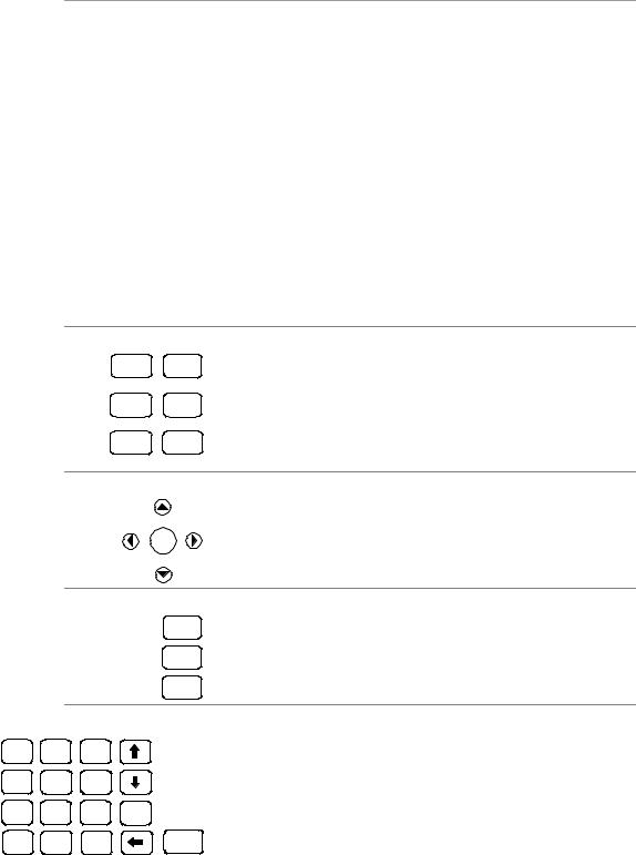
Front Panel Keys – At a Glance
System keys
Meter Menu
Channel Back
Help Error
Navigation keys
Sel
Output keys
On/Off
Voltage
Current
Number keys
7 |
8 |
9 |
|
4 |
5 |
6 |
|
1 |
2 |
3 |
E |
0 |
. |
+/- |
Enter |
Meter returns the display to metering mode. Menu accesses the command menu.
Channel selects or highlights a channel to control.
Back backs out of a menu without activating any changes. Help accesses information about the displayed menu control. Error displays any error messages in the error queue.
The Arrow keys let you move around in the command menus. The Select key lets you make a selection in the command menus. It also lets you enter edit mode for numeric parameters.
On/Off controls the selected output (or all outputs when All is lit). This key is only active in Singlechannel or Multiple-channel view. Voltage lets you change the voltage setting of the selected channel. Current lets you change the current setting of the selected channel.
The 0 through 9 keys enter numbers from 0 to 9. The (.) key enters a decimal point.
The +/− key is only used to enter a minus sign.
The E key enters an exponent. Add the value to the right of the E. The § backspace key deletes digits as it backspaces over them. The © ª arrow keys increment or decrement the value in certain fields. They are also used to select letters in alphabetic entry fields. The Enter key enters a value. If you exit a field without pressing the Enter key, the value is ignored.
12 |
Series N6700 User’s Guide |
|
|
|
Quick Reference 1 |
|
Front Panel Menu Reference |
|
|||
|
|
|
Menu commands that are grayed-out are either not available for the power |
|
|
|
NOTE |
|
|
|
|
|
module, or are password protected. Refer to the Service Guide for information |
|
|
|
|
about front panel menu commands prior to firmware revision B.00.00. |
|
|
|
|
|
|
|
|
|
|
|
Menu Command |
|
|
|
Control Description |
|
Output |
Voltage |
|
|
|
Programs voltage setting and range. |
|
|
|
|
|
|
|
Current |
|
|
|
Programs current setting and range. |
|
Delay |
|
|
|
Programs Turn-on /Turn off delay. |
|
|
|
|
|
|
|
Slew |
|
|
|
Programs voltage slew rate. |
|
Power |
|
|
|
Programs the power allocation function. |
|
Pol |
|
|
|
Lets you reverse the polarity of the output and sense terminals. |
|
|
|
|
|
|
|
Couple |
|
|
|
Couples output channels for output on/off synchronization. |
Measure |
Range |
|
|
|
Selects voltage and current measurement range. |
|
|
|
|
|
|
|
Sweep |
|
|
|
Specifies measurement points, time interval, and trigger offset. |
|
Window |
|
|
|
Selects measurement window: Rectangular, Hanning. |
|
Control |
|
|
|
Lets you abort a measurement in progress. |
|
|
|
|
|
|
Transient |
Mode |
|
|
|
Selects voltage or current transient mode: Fixed, Step, List. |
|
Step |
|
|
|
Programs voltage and current step value. Enables step triggers. |
|
|
|
|
|
|
|
List |
Pace |
|
|
Specifies Dwell or Trigger paced list. |
|
|
Repeat |
|
|
Specifies number of list repetitions, or specifies continuous list. |
|
|
|
|
|
|
|
|
Terminate |
|
|
Specifies list settings when the list terminates. |
|
|
|
|
|
|
|
|
Config |
|
|
Configures list step voltage, current, dwell, and trigger signals. |
|
|
Reset |
|
|
Aborts the list and resets all list parameters. |
|
|
|
|
|
|
|
TrigSource |
|
|
|
Specify the trigger source: Bus, Tran 1-4, Pin 1-7. |
|
|
|
|
|
|
|
Control |
|
|
|
Initiates, Triggers, or Aborts output triggers. Displays trigger state. |
Protect |
OVP |
|
|
|
Configures over-voltage protection function. |
|
OCP |
|
|
|
Configures over-current protection function. |
|
Inhibit |
|
|
|
Configures the external inhibit signal: Off, Latching, Live |
|
|
|
|
|
|
|
Coupling |
|
|
|
Disables ALL output channels when a protection fault occurs. |
|
Clear |
|
|
|
Clears output protection. Displays output state. |
|
|
|
|
|
|
States |
Reset |
|
|
|
Resets the instrument to its reset (*RST) state. |
|
SaveRecall |
|
|
|
Saves or recalls an instrument state. |
|
PowerOn |
|
|
|
Selects the power-on state: *RST, RCL0. |
|
|
|
|
|
|
System |
IO |
LAN |
ActiveSettings |
Displays the LAN interface settings that are presently active. |
|
|
|
|
Config |
IP |
Configures the IP addressing of the instrument. |
|
|
|
|
Name |
Configures the Dynamic DNS and NetBIOS naming service. |
|
|
|
|
|
|
|
|
|
|
Domain |
Configures the Domain Name. |
|
|
|
|
DNS |
Configures the DNS server. |
|
|
|
|
|
|
|
|
|
|
TCP |
Configures the TCP keepalive function. |
|
|
|
|
Reset |
Resets the LAN interface settings to the factory-shipped state. |
Series N6700 User’s Guide |
13 |

1 Quick Reference
Menu Command |
|
|
|
Control Description |
|
|
|
|
|
|
|
System |
IO |
USB |
Status |
|
Displays status, speed, packets received, and packets sent. |
|
|
|
Identification |
USB connect string - the instrument’s unique USB identifier. |
|
|
|
|
|
|
|
|
|
GPIB |
|
|
Selects the GPIB address. |
|
|
DigPort |
Pin1 |
Function |
Specifies the pin function: DigIn, DigIO, TrigIn, TrigOut, FaultOut. |
|
|
|
|
Polarity |
Specifies the pin polarity: Positive, Negative |
|
|
|
Pin2 |
Function |
Specifies the pin function: DigIn, DigIO, TrigIn, TrigOut. |
|
|
|
|
Polarity |
Specifies the pin polarity: Positive, Negative |
|
|
|
Pin3 |
Function |
Specifies the pin function: DigIn, DigIO, TrigIn, TrigOut, InhibitIn. |
|
|
|
|
Polarity |
Specifies the pin polarity: Positive, Negative |
|
|
|
Pin4 |
Function |
Specifies the pin function: DigIn, DigIO, TrigIn, TrigOut, OnC, OffC. |
|
|
|
|
Polarity |
Specifies the pin polarity: Positive, Negative |
|
|
|
Pin5 |
Function |
Specifies the pin function: DigIn, DigIO, TrigIn, TrigOut, OnC, OffC. |
|
|
|
|
Polarity |
Specifies the pin polarity: Positive, Negative |
|
|
|
Pin6 |
Function |
Specifies the pin function: DigIn, DigIO, TrigIn, TrigOut, OnC, OffC. |
|
|
|
|
Polarity |
Specifies the pin polarity: Positive, Negative |
|
|
|
Pin7 |
Function |
Specifies the pin function: DigIn, DigIO, TrigIn, TrigOut, OnC, OffC. |
|
|
|
|
Polarity |
Specifies the pin polarity: Positive, Negative |
|
|
|
Data |
|
Sends/reads data from the digital I/O port |
|
Groups |
|
|
|
Defines groups of output channels that are connected in parallel. |
|
Preferences |
Display |
Contrast |
|
Configures the display contrast. |
|
|
|
|
|
|
|
|
|
Saver |
|
Configures the screen saver and wake-on I/O timer. |
|
|
|
View |
|
Selects 1-channel or 4-channel view at turn-on |
|
|
|
|
|
|
|
|
Keys |
|
|
Enables/disables key clicks and configures the On/Off key. |
|
|
Lock |
|
|
Locks front panel keys. Enter a password to unlock the front panel. |
|
Admin |
Login/Logout |
|
Enter a password to access the admin functions. |
|
|
|
|
|
|
|
|
|
Cal |
Function |
Vprog |
High Enters measured data for the High calibration point. |
|
|
|
|
|
Low Enters measured data for the Low calibration point. |
|
|
|
|
Vmeas |
Enters measured data. |
|
|
|
|
CMRR |
Calibrates common mode rejection ratio. |
|
|
|
|
|
|
|
|
|
|
Iprog |
High Enters measured data for the High calibration point. |
|
|
|
|
|
Low Enters measured data for the Low calibration point. |
|
|
|
|
Imeas |
100mA Enters measured data for the 100 mA range point. |
|
|
|
|
|
100uA Enters measured data for the 100 A range point. |
|
|
|
|
Dprog |
Calibrates the downprogrammer. |
|
|
|
|
Ipeak |
Calibrates I peak. |
|
|
|
|
|
|
|
|
|
Date |
|
Saves the calibration date for each channel. |
|
|
|
Save |
|
Saves the calibration data. |
|
|
LAN |
|
|
Enables/disables the LAN interface and the built-in Web server. |
|
|
|
|
|
|
|
|
USB |
|
|
Enables/disables the USB interface. |
|
|
Nvram |
|
|
Resets all non-volatile RAM settings to their factory defaults. |
|
|
|
|
|
|
|
|
Password |
|
|
Changes the password for the admin functions. |
|
|
|
|
|
|
|
About |
Frame |
|
|
Displays model, serial number, and firmware revisions. |
|
|
Module |
|
|
Displays model, serial number, options, voltage, current, power. |
|
|
|
|
|
|
14 |
Series N6700 User’s Guide |
Quick Reference 1
SCPI Command Summary
Subsystem Commands
|
|
Some [optional] commands have been included for clarity. All settings commands |
|
|
NOTE |
||
|
have a corresponding query. Not all commands apply to all models. |
||
|
|
||
|
|
|
|
|
|
|
|
SCPI Command |
|
Description |
|
ABORt |
|
|
|
:ACQuire (@chanlist) |
|
Resets the measurement trigger system to the Idle state |
|
:TRANsient (@chanlist) |
|
Resets the transient trigger system to the Idle state |
|
CALibrate |
|
|
|
:CURRent |
|
|
|
[:LEVel] <NRf>, (@channel) |
|
Calibrates the output current programming |
|
:MEASure <NRf>, (@channel) |
|
Calibrates the current measurement |
|
:PEAK (@channel) |
|
Calibrates the peak current limit (Agilent N6751A/52A/61A/62A) |
|
:DATA <NRf> |
|
Enters the calibration value |
|
:DATE <SPD>, (@channel) |
|
Sets the calibration date |
|
:DPRog (@channel) |
|
Calibrates the current downprogrammer |
|
:LEVel P1 | P2 | P3 |
|
Advances to the next calibration step |
|
:PASSword <NRf> |
|
Sets the numeric calibration password |
|
:SAVE |
|
Saves the new cal constants in non-volatile memory |
|
:STATE <Bool> [,<NRf>] |
|
Enables/disables calibration mode |
|
:VOLTage |
|
|
|
[:LEVel] <NRf>, (@channel) |
|
Calibrates the output voltage programming |
|
:CMRR (@channel) |
|
Calibrates common mode rejection ratio (N6751A/52A/61A/62A) |
|
:MEASure <NRf>, (@channel) |
|
Calibrates the voltage measurement |
|
DISPlay[:WINDow]:VIEW METER1 | METER4 |
Selects 1-channel or 4-channel meter view |
||
FETCh |
|
|
|
[:SCALar] |
|
|
|
:CURRent [:DC]? (@chanlist) |
|
Returns the average output current |
|
:VOLTage [:DC]? (@chanlist) |
|
Returns the average output voltage |
|
:ARRay |
|
(Array commands only on Agilent N6761A/62A and Option 054) |
|
:CURRent [:DC]? (@chanlist) |
|
Returns the instantaneous output current |
|
:VOLTage [:DC]? (@chanlist) |
|
Returns the instantaneous output voltage |
|
INITiate |
|
|
|
[:IMMediate] |
|
(Acquire command only on Agilent N6761A/62A and Option 054) |
|
:ACQuire (@chanlist) |
|
Enables the measurement system to receive triggers |
|
:TRANsient (@chanlist) |
|
Enables the output transient system to receive triggers |
|
:CONTinuous |
|
|
|
:TRANsient <Bool>, (@chanlist) |
|
Enables/disables continuous transient triggers |
|
MEASure |
|
|
|
[:SCALar] |
|
|
|
:CURRent [:DC]? (@chanlist) |
|
Takes a measurement; returns the average output current |
|
:VOLTage [:DC]? (@chanlist) |
|
Takes a measurement; returns the average output voltage |
|
:ARRay |
|
(Array commands only on Agilent N6761A/62A and Option 054) |
|
:CURRent [:DC]? (@chanlist) |
|
Takes a measurement; returns the instantaneous output current |
|
:VOLTage [:DC]? (@chanlist) |
|
Takes a measurement; returns the instantaneous output voltage |
|
Series N6700 User’s Guide |
15 |

1 Quick Reference
SCPI Command |
Description |
OUTPut
[:STATe] <Bool> [,NORelay], (@chanlist) :COUPle[:STATe] <Bool>
:CHANNel [<NR1> {,<NR1>}] :DOFFset <NRf> :MAX:DOFFset?
:DELay
:FALL <NRf+>, (@chanlist) :RISE <NRf+>, (@chanlist)
:PMODe VOLTage | CURRent, (@chanlist) :INHibit:MODE LATChing | LIVE | OFF :PON:STATe RST | RCL0
:PROTection
:CLEar (@chanlist) :COUPle <Bool>
:DELay <NRf+>, (@chanlist)
:RELay:POLarity NORMal | REVerse, (@chanlist)
SENSe :CURRent
[:DC]:RANGe [:UPPer] <NRf+>, (@chanlist) CCOMpensate <Bool>, (@chanlist)
:FUNCtion “VOLTage” | ”CURRent”, (@chanlist) :SWEep
:OFFSet:POINts <NRf+>, (@chanlist) :POINts <NRf+>, (@chanlist) :TINTerval <NRf+>, (@chanlist)
:VOLTage[:DC]:RANGe [:UPPer] <NRf+>, (@chanlist) :WINDow[:TYPE] HANNing | RECTangular, (@chanlist)
[SOURce:] CURRent
[:LEVel]
[:IMMediate][:AMPLitude] <NRf+>, (@chanlist) :TRIGgered [:AMPLitude] <NRf+>, (@chanlist)
:MODE FIXed | STEP | LIST, (@chanlist) :PROTection
:DELay[:TIME] <NRf+>, (@chanlist)
:STARt SCHange | CCTRans, (@chanlist) :STATe <Bool>, (@chanlist)
:RANGe <NRf+>, (@chanlist) DIGital
:INPut:DATA? :OUTPut:DATA <NRf> :PIN<1-7>
:FUNCtion DIO|DINP|TOUT|TINP|FAUL|INH|ONC|OFFC :POLarity POSitive | NEGative
LIST
:COUNt <NRf+> | INFinity, (@chanlist) :CURRent [:LEVel] <NRf> {,<NRf>}, (@chanlist)
:POINts? (@chanlist)
:DWELl <NRf> {,<NRf>}, (@chanlist) :POINts? (@chanlist)
Enables/disables the specified output channel(s) Enables/disables channel coupling for output synchronization Selects which channels are coupled
Specifies a maximum delay offset to synchronize output changes Returns the maximum delay offset required for a mainframe
Sets the output turn-off sequence delay Sets the output turn-on sequence delay
Sets the mode for turn on/off transitions (Agilent N6761A/62A) Sets the remote inhibit input
Programs the power-on state
Resets latched protection
Enables/disables channel coupling for protection faults Sets over-current protection programming delay
Sets the output relay polarity (Option 760)
Selects the current measurement range (Agilent N6761A/62A) Enables/disables the capacitive current compensation Selects the measurement function
(Sweep commands only on Agilent N6761A/62A and Option 054) Defines the trigger offset in the measurement sweep
Defines the number of data points in the measurement Sets the measurement sample interval
Selects the voltage measurement range (Agilent N6761A/62A) Selects the measurement window (N6761A/62A and Option 054)
Sets the output current
Sets the triggered output current
Sets the current trigger mode
Sets the over-current protection programming delay Sets the over-current protection programming mode
Enables/disables over-current protection on the selected output Sets the output current range (Agilent N6761A/62A)
Reads the state of the digital port pins
Sets the digital port
Sets the selected pin’s function Sets the selected pin’s polarity
(List commands only on Agilent N6761A/62A and Option 054) Sets the list repeat count
Sets the current list
Returns the number of current list points Sets the list of dwell times
Returns the number of dwell list points
16 |
Series N6700 User’s Guide |
|
Quick Reference 1 |
|
|
SCPI Command |
Description |
[SOURce:]LIST (continued) |
|
:STEP ONCE | AUTO, (@chanlist) |
Specifies how the list responds to triggers |
:TERMinate:LAST <Bool>, (@chanlist) |
Sets the list termination mode |
:TOUTput |
|
:BOSTep[:DATA] <Bool> {,<Bool>}, (@chanlist) |
Generate triggers at the Beginning Of Step |
:POINts? (@chanlist) |
Returns the number of beginning of step list points |
:EOSTep[:DATA] <Bool> {,<Bool>}, (@chanlist) |
Generate triggers at the End Of Step |
:POINts? (@chanlist) |
Returns the number of end of step list points |
:VOLTage[:LEVel] <NRf> {,<NRf>}, (@chanlist) |
Sets the voltage list |
:POINts? (@chanlist) |
Returns the number of voltage level points |
POWer:LIMit <NRf+>, (@chanlist) |
Sets the power limit on output channels |
STEP:TOUTput <Bool>, (@chanlist) |
Generate a trigger output on the voltage or current step transient |
VOLTage |
|
[:LEVel] |
|
[:IMMediate][:AMPLitude] <NRf+>, (@chanlist) |
Sets the output voltage |
:TRIGgered [:AMPLitude] <NRf+>, (@chanlist) |
Sets the triggered output voltage |
:MODE FIXed | STEP | LIST, (@chanlist) |
Sets the voltage trigger mode |
:PROTection[:LEVel] <NRf+>, (@chanlist) |
Sets the over-voltage protection level |
:RANGe <NRf+>, (@chanlist) |
Sets the output voltage range (Agilent N6761A/62A) |
:SLEW[:IMMediate] <NRf+> | INFinity, (@chanlist) |
Sets the output voltage slew rate |
STATus |
|
:OPERation |
|
[:EVENt]? (@chanlist) |
Returns the value of the operation event register |
:CONDition? (@chanlist) |
Returns the value of the operation condition register |
:ENABle <NRf>, (@chanlist) |
Enables specific bits in the Event register |
:NTRansition <NRf>, (@chanlist) |
Sets the Negative transition filter |
:PTRansition <NRf>, (@chanlist) |
Sets the Positive transition filter |
:PRESet |
Presets all enable and transition registers to power-on |
:QUEStionable |
|
[:EVENt]? (@chanlist) |
Returns the value of the questionable event register |
:CONDition? (@chanlist) |
Returns the value of the questionable condition register |
:ENABle <NRf>, (@chanlist) |
Enables specific bits in the Event register |
:NTRansition <NRf>, (@chanlist) |
Sets the Negative transition filter |
:PTRansition <NRf>, (@chanlist) |
Sets the Positive transition filter |
SYSTem |
|
:CHANnel[:COUNt]? |
Returns the number of output channels in a mainframe |
:MODel? (@chanlist) |
Returns the model number of the selected channel |
:OPTion? (@chanlist) |
Returns the option installed in the selected channel |
:SERial? (@chanlist) |
Returns the serial number of the selected channel |
:COMMunicate |
|
:RLSTate LOCal | REMote | RWLock |
Specifies the Remote/Local state of the instrument |
:TCPip:CONTrol? |
Returns the control connection port number |
:ERRor? |
Returns the error number and error string |
:GROup |
|
:CATalog? |
Returns the groups that have been defined |
:DEFine (@chanlist) |
Group multiple channels together to create a single output |
:DELete <channel> |
Removes the specified channel from a group |
:ALL |
Ungroups all channels |
:PASSword:FPANel:RESet |
Resets the front panel lock password to zero |
:REBoot |
Returns the unit to its power-on state |
:VERSion? |
Returns the SCPI version number |
Series N6700 User’s Guide |
17 |

1 Quick Reference
SCPI Command |
Description |
TRIGger |
|
:ACQuire |
(Acquire commands only on Agilent N6761A/62A and Option 054) |
[:IMMediate] (@chanlist) |
Triggers the measurement immediately |
:SOURce BUS | PIN<n> | TRAN<n>, (@chanlist) |
Sets the measurement trigger source |
:TRANsient |
|
[:IMMediate] (@chanlist) |
Triggers the output immediately |
:SOURce BUS | PIN<n> | TRAN<n>, (@chanlist) |
Sets the output trigger source |
Common Commands
Command |
Description |
Command |
Description |
*CLS |
Clear status |
*RST |
Reset |
*ESE <NRf> |
Standard event status enable |
*SAV <NRf> |
Saves an instrument state |
*ESR? |
Return event status register |
*SRE <NRf> |
Set service request enable register |
*IDN? |
Return instrument identification |
*STB? |
Return status byte |
*OPC |
Enable "operation complete" bit in ESR |
*TRG |
Trigger |
*OPT? |
Return option number |
*TST? |
Performs self-test, then returns result |
*RCL <NRf> |
Recalls a saved instrument state |
*WAI |
Pauses additional command processing |
*RDT? |
Return output channel descriptions |
|
until all device commands are done |
*RST Settings
These settings are set by the *RST (Reset) command
CAL:STAT |
OFF |
OUTP:PMOD |
VOLT |
[SOUR:]CURR |
0.08 or MIN |
OUTP:PROT:COUP |
OFF |
[SOUR:]CURR:MODE |
FIX |
OUTP:PROT:DEL |
0.02 |
[SOUR:]CURR:PROT:STAT |
OFF |
OUTP:REL:POL |
NORM |
[SOUR:]CURR:RANG |
MAX |
[SOUR:]POW:LIM |
MAX |
[SOUR:]CURR:TRIG |
MIN |
SENS:CURR:RANG |
MAX |
[SOUR:]DIG:OUTP:DATA |
0 |
SENS:FUNC |
“VOLT” |
DISP:VIEW |
METER1 |
SENS:SWE:POIN |
1024 |
INIT:CONT:TRAN |
OFF |
SENS:SWE:OFFS:POIN |
0 |
[SOUR:]LIST:COUN |
1 |
SENS:SWE:TINT |
20.48E−6 |
[SOUR:]LIST:CURR |
MIN |
SENS:VOLT:RANG |
MAX |
[SOUR:]LIST:DWEL |
0.001 |
SENS:WIND |
RECT |
[SOUR:]LIST:STEP |
AUTO |
[SOUR:]STEP:TOUT |
FALSE |
[SOUR:]LIST:TERM:LAST |
OFF |
TRIG:ACQ:SOUR |
BUS |
[SOUR:]LIST:TOUT:BOST |
OFF |
TRIG:TRAN:SOUR |
BUS |
[SOUR:]LIST:TOUT:EOST |
OFF |
[SOUR:]VOLT |
MIN |
[SOUR:]LIST:VOLT |
MIN |
[SOUR:]VOLT:MODE |
FIX |
OUTP |
OFF |
[SOUR:]VOLT:PROT |
MAX |
OUTP:DEL:FALL |
0 |
[SOUR:]VOLT:RANG |
MAX |
OUTP:DEL:RISE |
0 |
[SOUR:]VOLT:SLEW |
9.9E+37 |
|
|
[SOUR:]VOLT:TRIG |
MIN |
18 |
Series N6700 User’s Guide |

2 Installation
General Information.......................................................................................... |
20 |
Inspecting the Unit ........................................................................................... |
21 |
Installing the Unit.............................................................................................. |
21 |
Connecting the Line Cord ................................................................................ |
24 |
Connecting the Outputs................................................................................... |
25 |
Remote Sense Connections ............................................................................ |
29 |
Parallel Connections......................................................................................... |
30 |
Series Connections........................................................................................... |
32 |
This chapter describes how to install your power system. It discusses rack mounting and line cord connections.
This chapter also discusses how to connect your load to the output terminals. It discusses what you need to know about wire sizes and how to compensate for voltage drops in the load leads. It describes various loads configurations and how to connect the output terminals in series and parallel.
Before installing the instrument, check the list under “Items Supplied” and verify that you have received these items with your instrument. If anything is missing, please contact your nearest Agilent Sales and Support Office.
Series N6700 User’s Guide |
19 |

2 Installation
General Information
Models
Agilent Model |
Description |
N6700B / N6701A / N6702A |
400 W / 600 W / 1200W MPS Mainframe - without DC Power Modules |
N6751A / N6752A |
50 W / 100 W High-Performance Autoranging DC Power Module |
N6753A / N6754A |
300 W 20V / 60V High-Performance Autoranging DC Power Module |
N6761A / N6762A |
50 W / 100 W Precision DC Power Module |
N6731B / N6741B |
50 W / 100 W 5 V DC Power Module |
N6732B / N6742B |
50 W / 100 W 8 V DC Power Module |
N6733B / N6743B / N6773A |
50 W / 100 W / 300 W 20 V DC Power Module |
N6734B / N6744B / N6774A |
50 W / 100 W / 300 W 35 V DC Power Module |
N6735B / N6745B / N6775A |
50 W / 100 W / 300 W 60 V DC Power Module |
N6736B / N6746B / N6776A |
50 W / 100 W / 300 W 100 V DC Power Module |
Items Supplied
Item |
Description |
Part Number |
Power Cord |
A power cord suitable for your location. Shipped w/mainframe. |
Call Agilent Sales & Support Office |
Ferrite Core |
Installs on power cord to reduce common mode currents. |
Agilent 9170-2131 |
Digital Connector |
One 8-pin connector for connecting signal lines to the digital |
Agilent 1253-6408 |
|
port. Shipped with mainframe. |
Phoenix Contact MC 1,5/8-ST-3,5 |
Product Reference CD-ROM |
Includes drivers and documentation. Shipped with mainframe. |
Agilent 5969-2914 |
Automation-Ready CD-ROM |
Contains Agilent IO Libraries Suite. Shipped with mainframe. |
Agilent E2094N |
12 A Output Connector |
One 12A, 4-pin connector plug for connecting power and sense |
Agilent 1253-5826 |
|
leads. Used in all except N6731B, N6741B, N6754A, N6773A. |
Phoenix Contact MSTB 2,5/4-STF |
20 A Output Connector |
One 20A, 4-pin connector plug for connecting power and sense |
Agilent 1253-6211 |
|
leads. Only used in N6731B, N6741B, N6754A, N6773A. |
Phoenix Contact PC 4/4-ST-7,62 |
50 A Output Connector |
One 50A, 2-pin connector plug for connecting power leads. |
Agilent 1253-7187 |
|
Only used in N6753A. |
Molex 39422-0002 |
Small Sense Jumpers |
Two small jumpers for local sensing at the output connector. |
Agilent 8120-8821 |
|
Used in all except N6731B, N6741B, N6754A, N6773A. |
Phoenix Contact EPB 2-5(1733169) |
Large Sense Jumpers |
Two large jumpers for local sensing at the output connector. |
Agilent 0360-2935 |
|
Only used in N6731B, N6741B, N6754A, N6773A. |
Phoenix Contact 3118151 |
Sense Connector |
A 4-pin connector for connecting sense leads. Wires (p/n |
Agilent 1253-5830 |
|
5185-8847) are used for local sensing. Only used in N6753A. |
Phoenix Contact MC 1,5/4-ST-3,5 |
Module Cal. Certificate |
A certificate of calibration referenced to the serial number. |
N/A |
|
Options |
|
|
Option |
Description |
0L1 |
Manual Set. Contains User’s Guide and Service Guide. Also available as part number 5969-2939. |
054 |
High-speed Test Extensions. Includes digitized output measurements and output list capability. |
|
Available for Agilent Models N675xA. Included with Agilent Models N676xA. |
760 |
Output disconnect/polarity reversal. Disconnects the + and – output and sense terminals. Switches |
|
the + and – output and sense polarities. Not available on Models N6741B, N675xA, or N676xA. |
761 |
Output disconnect. Disconnects + and – output and sense terminals. Available for all Agilent Models. |
908 |
Rack Mount Kit. For mounting in a 19-inch EIA rack cabinet. Also available as Model N6709A. |
FLR |
Filler module. For mainframes with less than four power modules. Also available as Model N6708A. |
2UA |
200 μA measurement range with output disconnect relays. Only available on Agilent Models N676xA. |
20 |
Series N6700 User’s Guide |
Installation 2
Inspecting the Unit
When you receive your power system, inspect it for any obvious damage that may have occurred during shipment. If there is damage, notify the shipping carrier and nearest Agilent Sales and Support Office immediately. Refer to www.agilent.com/find/assist.
Until you have checked out the power system, save the shipping carton and packing materials in case the unit has to be returned.
Installing the Unit
Safety Considerations
This power system is a Safety Class 1 instrument, which means it has a protective earth terminal. That terminal must be connected to earth ground through a power source equipped with a ground receptacle.
Refer to the Safety Summary page at the beginning of this guide for general safety information. Before installation or operation, check the power system and review this guide for safety warnings and instructions. Safety warnings for specific procedures are located at appropriate places throughout this Guide.
Environment
WARNING Do not operate the instrument in the presence of flammable gasses or fumes
The environmental conditions of the instrument are documented in Appendix A. Basically, the instrument should only be operated indoors in a controlled environment.
The dimensions of your instrument as well as an outline diagram are given in Appendix A. A fan cools the power system by drawing air through the sides and exhausting it out the side and back. The instrument must be installed in a location that allows sufficient space at the sides and back of the unit for adequate air circulation.
Rack Installation
|
|
You cannot use support rails for rack mounting your instrument. |
|
CAUTION |
|
|
|
Support rails would block the airflow needed for cooling. |
|
|
Use Rack Mount kit (Option 908) to rack mount your instrument. |
|
|
The Rack Mount Kit is also available by ordering part number N6709A. |
|
|
|
|
|
Agilent N6700 MPS mainframes can be mounted in a 19-inch EIA |
|
|
rack cabinet. They are designed to fit in one rack-unit (1U) of space. |
|
|
Do not block the air intake and exhaust at the sides of the unit, or the |
|
|
exhaust at the rear of the unit. |
Series N6700 User’s Guide |
21 |
|
2 Installation
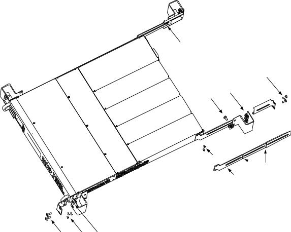
Tools required: Phillips driver, T22 Torx driver, T10 Torx driver
Step 1. Install eight clip-nuts on the rack frame (2 in each corner) where your instrument will be located.
Step 2. Install the two front ears and the two rear extender supports on the instrument as shown in the figure. Use six M3 x 8mm screws (a) for the front ears and four M3 x 6mm screws (b) for the extender supports. If the standard extender supports are either too short or too long, use the longer supports (c). Cut the supports if required (d).
Step 3. Install the two rear ears on the back of the instrument rack as shown in the figure. Use four plain 10-32 screws to install the rear ears.
Step 4. Slide the instrument into the rack. making sure that the rear extender supports are aligned inside the rear ears.
Step 5. Attach the front ears to the front of the instrument rack using the four dress 10-32 screws provided.
Step 6. This is optional. Insert a plain 10-32 screw through the slot of the rear ear and extender support. Attach it with a clip-nut. Note that this will prevent the unit from being slid out of the front of the rack.
4
3
1
6
2b
 2d
2d
2c
5 2a 1
22 |
Series N6700 User’s Guide |

Installation 2
Bench Installation
Do not block the air intake and exhaust at the sides, or the exhaust at the rear of the unit. Refer to the outline diagram in Appendix A.
Minimum clearances for bench operation are 2 inches (51 mm) along the sides and back.
Channel Number
|
The channel number of a power module is determined by the location |
|
|
of that module in the mainframe. When viewed from the rear, the |
|
|
module next to the GPIB connector is always output channel one. |
|
|
Numbering continues sequentially to the left, from one to four. |
|
|
If there are less than four modules, channel numbering corresponds |
|
|
to the actual number of installed power modules. Unused channel |
|
|
slots must contain filler modules to ensure proper airflow for cooling. |
|
|
Double-wide power modules are assigned the channel number of the |
|
|
lowest numbered slot in which is installed. For example, if a double- |
|
|
wide module is installed in slots 3 and 4, it is assigned channel |
|
|
number 3. |
|
|
Power modules that are connected in parallel and have been configured or |
|
NOTE |
||
grouped to act as a single, higher-power channel are addressed using the |
||
|
||
|
channel number of the lowest channel in the group. |
|
|
|
400 Hz Operation
Redundant Ground Requirement
At 400 Hz AC input operation, the leakage current of the unit exceeds 3.5 mA. This requires the installation of a permanent, redundant ground from the instrument chassis to earth ground. This ensures that ground will always be connected and that any leakage current will be diverted to ground. Refer to the Service Guide for installation instructions.
Power Factor
At 400 Hz AC input operation, the unit’s power factor is affected as follows:
Under full load at 400 Hz, power factor drops from 0.99 (@120
VAC) to as low as 0.76 (@ 265 VAC).
Power factor degrades further under no load conditions.
Cleaning
WARNING SHOCK HAZARD To prevent electric shock, unplug the unit before cleaning.
Use a dry cloth or one slightly dampened with water to clean the external case parts. Do not attempt to clean internally.
Series N6700 User’s Guide |
23 |
2 Installation
Connecting the Line Cord
|
FIRE HAZARD Use only the power cord that was supplied with your |
|
WARNING |
||
instrument. Using other types of power cords may cause overheating of the |
||
|
||
|
power cord, resulting in fire. |
|
|
SHOCK HAZARD The power cord provides a chassis ground through a third |
|
|
conductor. Be certain that your power outlet is of the three-conductor type |
|
|
with the correct pin connected to earth ground. |
|
|
|
|
|
Connect the power cord to the IEC 320 connector on the rear of the |
|
|
unit. If the wrong power cord was shipped with your unit, contact |
|
|
your nearest Agilent Sales and Support Office. |
|
|
The AC input on the back of your unit is a universal AC input. It |
|
|
accepts nominal line voltages in the range of 100 VAC to 240 VAC. |
|
|
The frequency can be 50 Hz, 60 Hz, or 400 Hz. |
|
|
Agilent N6702A Mainframe Note: Standard AC mains circuits rated |
|
|
at nominal 100-120 VAC cannot supply enough current to power the |
|
|
N6702A mainframe when it is operated at its full rated power. |
|
|
Nevertheless, the N6702A can be connected to an AC mains circuit |
|
|
rated at nominal 100-120 VAC. In this case, internal circuits will limit |
|
|
the power available to modules to 600 W. As a result of this power |
|
|
limiting, the current drawn from the AC mains will be < 15 A, so that |
|
|
standard 100-120 VAC AC mains circuits will not be overloaded. |
|
|
The detachable power cord may be used as an emergency disconnecting |
|
NOTE |
||
device. Removing the power cord will disconnect AC input power to the unit. |
||
|
||
|
|
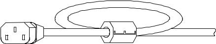
Snap-On Ferrite Core
Installing the ferrite core is only necessary if you are connecting highly sensitive loads to the output of the modular power system. The purpose of the ferrite core is to reduce the possibility of common mode current spikes appearing at the output of the modular power system when AC power is switched on or off.
Additional measures to protect sensitive loads from common mode currents are discussed under “Protecting Sensitive Loads from AC Power Switching Transients” later in this chapter.
Installation
Locate the core anywhere along the length of the cord.
Pass the power cord through the core twice.
Close the core.
24 |
Series N6700 User’s Guide |
Installation 2
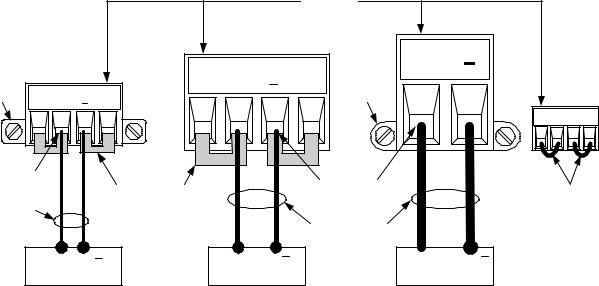
Connecting the Outputs
|
SHOCK HAZARD Turn off AC power before making rear panel connections. |
|
WARNING |
||
All wires and straps must be properly connected with the terminal block |
||
|
||
|
screws securely tightened. |
|
|
|
|
|
Disconnect the connector plug to make your wire connections. The |
|
|
12A connector plug accepts wires sizes from AWG 12 to AWG 30. The |
|
|
20A connector plug accepts wires sizes from AWG 10 to AWG 24. The |
|
|
50A connector plug accepts wires sizes from AWG 6 to AWG 20. Wire |
|
|
sizes smaller than AWG 20 are not recommended. Connect the load |
|
|
wires to the + and - terminals. Connect the sense wires to the +s and |
|
|
-s terminals. Sense jumpers are provided for local sensing. |
|
|
Securely fasten all wires by tightening the screw terminals. Insert the |
|
|
connector plug into the back of the unit. Secure the 12 A connector |
|
|
by tightening the locking screws. A chassis ground binding post is |
|
|
located next to the AC input connector for ground connections. |
|
|
On power modules with the 50A sense connector, the +LS and –LS terminals |
|
CAUTION |
||
|
are ONLY used for local sense connections as illustrated. Do not connect these |
|
|
terminals in any other way. |
|
|
|
|
|
|
|
|
TIGHTEN |
|
|
|
|
|
|
SCREWS |
|
|
|
|
|
20 A CONNECTOR |
|
|
|
|
12 A |
|
|
|
|
LOCKING |
CONNECTOR |
+S |
+ |
-S |
LOCKING |
|
|
|
|||||
SCREW |
+S |
+ |
-S |
|
|
SCREW |
|
|
|
|
|||
INSERT WIRES |
|
SENSE JUMPERS |
|
INSERT WIRES |
||
|
|
|
|
|||
TWIST LEADS |
|
|
|
|
||
|
INSTALLED FOR |
|
|
|
||
|
|
|
LOCAL SENSING |
|
TWIST LEADS |
|
|
|
|
|
|
||
|
|
+ |
|
+ |
|
|
|
|
LOAD |
|
LOAD |
|
|
50 A |
CONNECTOR |
+ |
+
LOAD
50A |
SENSE |
+S +LS -LS -S |
SENSE JUMPERS INSTALLED FOR LOCAL SENSING
Series N6700 User’s Guide |
25 |
2 Installation
Wire Size
|
|
FIRE HAZARD Select a wire size large enough to carry short-circuit current |
|
|||||
|
WARNING |
|
||||||
|
without overheating. To satisfy safety requirements, load wires must be |
|
||||||
|
|
|
||||||
|
|
heavy enough not to overheat while carrying the short-circuit output current |
|
|||||
|
|
of the unit (refer to the following table). |
|
|
|
|
||
|
|
|
|
|||||
|
|
Along with conductor temperature, you must also consider voltage |
|
|||||
|
|
drop when selecting wire sizes. The following table lists the |
|
|
||||
|
|
resistance for various wire sizes and the maximum lengths to limit |
|
|||||
|
|
the voltage drop to 1.0 V per lead for various currents. |
|
|
||||
|
|
Note that the minimum wire size required to prevent overheating |
|
|||||
|
|
may not be large enough to prevent over-voltage tripping or maintain |
|
|||||
|
|
good regulation. Under most conditions, the load wires should also be |
|
|||||
|
|
heavy enough to limit the voltage drop to no more than l.0 V per lead. |
|
|||||
|
|
To help prevent nuisance tripping of the over-voltage circuit, select a |
|
|||||
|
|
wire size sufficient to handle the FULL output current of the unit no |
|
|||||
|
|
matter what the intended load current or current limit setting |
|
|
||||
|
|
Load lead resistance is also an important factor relating to the CV |
|
|||||
|
|
stability of the instrument when remote sensing capacitive loads. If |
|
|||||
|
|
high capacitance loads are expected, you should not use wire gauges |
|
|||||
|
|
heavier than 12 to 14 AWG for long runs of load lead. |
|
|
||||
|
|
|
|
|
||||
Wire size |
Current-carrying capacity in Amps |
Resistance |
Max. Length to Limit Voltage to 1 V/Lead |
|
||||
|
for stranded copper wire |
|
for 5 A |
for 10 A |
for 20A |
for 50 A |
|
|
AWG |
2 wires bundled |
4 wires bundled |
Ω/foot |
Wire length in feet |
|
|
|
|
20 |
7.8 |
6.9 |
0.0102 |
20 |
x |
x |
x |
|
18 |
14.5 |
12.8 |
0.0064 |
30 |
15 |
x |
x |
|
16 |
18.2 |
16.1 |
0.0040 |
50 |
25 |
x |
x |
|
14 |
29.3 |
25.9 |
0.0025 |
80 |
40 |
20 |
x |
|
12 |
37.6 |
33.2 |
0.0016 |
125 |
63 |
30 |
x |
|
10 |
51.7 |
45.7 |
0.0010 |
200 |
100 |
50 |
20 |
|
8 |
70.5 |
62.3 |
0.0006 |
320 |
160 |
80 |
32 |
|
6 |
94 |
83 |
0.0004 |
504 |
252 |
126 |
50 |
|
Area in mm2 |
2 wires bundled |
4 wires bundled |
Ω/meter |
Wire length in meters |
|
|
|
|
0.5 |
7.8 |
6.9 |
0.0401 |
5 |
x |
x |
x |
|
0.75 |
9.4 |
8.3 |
0.0267 |
7.4 |
x |
x |
x |
|
1 |
12.7 |
11.2 |
0.0200 |
10 |
5 |
x |
x |
|
1.5 |
15.0 |
13.3 |
0.0137 |
14.6 |
7.2 |
x |
x |
|
2.5 |
23.5 |
20.8 |
0.0082 |
24.4 |
12.2 |
6.1 |
x |
|
4 |
30.1 |
26.6 |
0.0051 |
39.2 |
19.6 |
9.8 |
3.9 |
|
6 |
37.6 |
33.2 |
0.0034 |
58 |
29 |
14.7 |
5.9 |
|
10 |
59.2 |
52.3 |
0.0020 |
102 |
51 |
25 |
10.3 |
|
Notes: 1. Capacity for AWG wires derived from MIL-W-5088B. Max. ambient temp: 55°C. Max. wire temp: 105°C.
2.Capacity for metric wires are derived from IE Publication 335-1.
3.Capacity of aluminum wire is approximately 84% of that listed for copper wire.
4.“x” indicates wire is not rated for the maximum output current of the power module.
5.Because of wire inductance considerations, it is also recommended that you keep your load leads twisted, tie wrapped, or bundled together and less than 50 feet (14.7 meters) in length per lead.
26 |
Series N6700 User’s Guide |
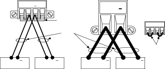
Installation 2
Multiple Loads
If you are using local sensing and are connecting multiple loads to one output, connect each load to the output terminals using separate connecting wires as shown in the following figure.
12A & 20 A CONNECTOR
+S |
+ |
-S |
50 A
+CONNECTOR
SENSE JUMPERS
INSTALLED FOR 50A SENSE LOCAL SENSING
+S +LS -LS -S
TWIST
 LEADS
LEADS
|
SENSE JUMPERS |
|
TWIST LEADS |
INSTALLED FOR |
|
LOCAL SENSING |
||
|
+ |
+ |
+ |
+ |
LOAD |
LOAD |
LOAD |
LOAD |
This minimizes mutual coupling effects and takes full advantage of the power system's low output impedance. Keep each pair of wires as short as possible and twist or bundle them to reduce lead inductance and noise pickup.
If load considerations require the use of distribution terminals that are located away from the instrument, connect the output terminals to the remote distribution terminals by a pair of twisted or bundled wires. Connect each load to the distribution terminals separately.
Remote voltage sensing is recommended under these circumstances. Sense either at the remote distribution terminals or, if one load is more sensitive than the others, directly at the critical load.
Response Time with an External Capacitor
When programming with an external capacitor, voltage response time may be longer than that specified in Appendix A. Use the following formula to estimate the additional response time for up programming:
Response Time = (Added Output Capacitor)X(Change in Vout) Current Limit Setting
Note that programming into an external output capacitor may cause the power system to briefly enter constant current or constant power operating mode, which adds additional time to the estimation.
Positive and Negative Voltages
Either positive or negative voltages can be obtained from the output by grounding (or "commoning") one of the output terminals. Always use two wires to connect the load to the output regardless of where or how the system is grounded. The instrument can be operated with any output terminal ± 240 VDC including output voltage from ground.
Series N6700 User’s Guide |
27 |
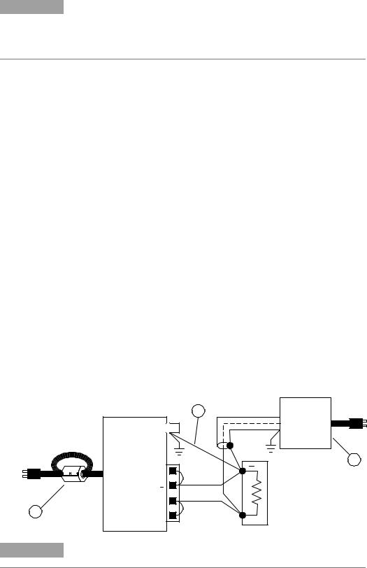
2 Installation
Protecting Sensitive Loads from AC Power Switching Transients
This only applies if you are connecting loads that are highly sensitive to voltage NOTE or current transients to the output of the modular power system. If your load is
connected directly to the output of the power system and is not connected to chassis ground in any way, you do not need to worry about AC power switching transients appearing at the output of the modular power system.
Operating the AC line switch can inject common mode current spikes into the DC output leads, resulting in voltage spikes, which may damage sensitive loads. Note that any electronic device meeting international standards for EMI compliance is likely to generate similar current spikes. This situation arises from the presence of EMI filters at both the AC input and the DC output of the modular power system. These filters typically include common mode capacitors connected to the power system chassis. Since the AC input has an earth ground, any load that is also earth-grounded provides a possible return path for common mode currents.
The following figure illustrates a typical situation where a load that might otherwise be floating becomes grounded, thereby providing a return path for any injected currents. In this case, the return path is created by the low side of the scope probe, which is connected to the load circuit common and also to the scope’s chassis. For this and similar cases, the following steps by order of preference, will help mitigate common mode current spikes appearing at the output when the modular power system is turned on or off by the AC line switch:
1Install the ferrite core on the power cord as described under "Snap-On Core". This inserts impedance in the current path.
2Install a separate “bonding” wire from the load’s common point, to the ground terminal of the modular power system. This provides a lower impedance path that helps direct injected currents away from the DC output leads (and the sensitive load).
3Break the return path through the external equipment. For example, instead of the single-ended scope shown in the figure, you can use a differential scope with a floating input or you can connect an isolated measuring instrument to the load.
1
NOTE
2 |
Scope |
probe
N6700 Modular
Power System
3
-S |
|
+ |
|
+S |
+ |
|
Disconnecting the load from the output before switching the modular power system on or off will always protect the load from common mode currents.
28 |
Series N6700 User’s Guide |
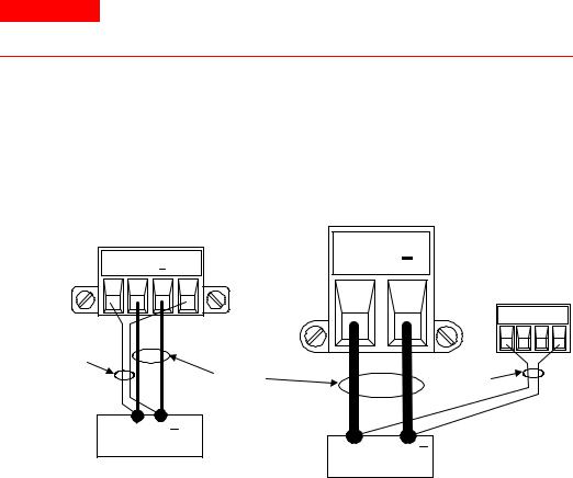
Installation 2
Remote Sense Connections
WARNING SHOCK HAZARD Turn off AC power before making or changing rear panel connections.
Remote sensing improves the voltage regulation at the load by monitoring the voltage there instead of at the output terminals. This allows the power system to automatically compensate for the voltage drop in the load leads. Remote sensing is especially useful for CV operation with load impedances that vary or have significant lead resistance. It has no effect during CC operation. Because sensing is independent of other power system functions, remote sensing can be used regardless of how the power system is programmed.
|
|
|
|
+ |
50 A |
12A & 20 A |
+S |
+ |
-S |
CONNECTOR |
|
CONNECTOR |
|
|
|||
|
|
|
|
|
50A SENSE |
|
|
|
|
|
+S +LS -LS -S |
TWIST |
|
|
|
|
|
PAIR |
|
|
TWIST |
|
TWIST |
|
|
|
|
||
|
|
|
LEADS |
|
PAIR |
|
+ |
LOAD |
|
+ |
|
|
|
|
LOAD |
||
|
|
|
|
|
Connect the unit for remote sensing by first disconnecting the straps between sense and load terminals. Make your connections as shown in the following figure. Connect the sense leads as close to the load as possible. Refer to the “Wire Size” section for information about selecting the proper wire size. Best results are obtained by using the shortest load leads practical. It is recommended to keep load leads under 14.7 meters (50 feet) per lead because of inductance effects.
The sense leads carry only a few milliamperes of current and can be a lighter gauge than the load leads. However, note that any voltage drop in the sense leads can degrade the voltage regulation of the instrument. Try to keep the sense lead resistance less than about 0.5Ω per lead (this requires 20 AWG or heavier for a 50 foot length).
|
When remote sensing on power modules with the 50A sense connector, do not |
CAUTION |
|
|
connect the +LS and –LS terminals. These are dedicated for local sensing only. |
|
|
Series N6700 User’s Guide |
29 |
2 Installation
Open Sense Leads
The sense leads are part of the output's feedback path. Connect them in such a way so that they do not inadvertently become open circuited. The power system includes protection resistors that reduce the effect of open sense leads during remote-sensing operation. If the sense leads open during operation, the power system returns to the local sensing mode, with the voltage at the output terminals approximately 1% higher than the programmed value.
Over-voltage Protection Considerations
The OVP circuit senses at the main output terminals and not through the sense terminals. Due to the voltage drop in the load leads, the voltage sensed by the OVP circuit could be higher than the voltage being regulated at the load. Therefore, you must take into account the additional voltage drop in the load leads when setting the overvoltage trip point.
Output Noise Considerations
Any noise picked up on the sense leads will appear at the output terminals and may adversely affect CV load regulation. Twist the sense leads or use a ribbon cable to minimize the pickup of external noise. In extremely noisy environments it may be necessary to shield the sense leads. Ground the shield at the power system end only; do not use the shield as one of the sensing conductors.
The noise specifications in Appendix A apply at the output terminals when using local sensing. However, voltage transients may be produced at the load by noise induced in the leads or by load current transients acting on the inductance and resistance of the load lead. If it is desirable to keep voltage transient levels to a minimum, place an aluminum or tantalum capacitor, with an approximate value of 10 F per foot (30.5 cm) of load lead, right across the load.
Parallel Connections
|
Only connect outputs that have identical voltage and current ratings in parallel. |
CAUTION |
|
|
|
Connecting outputs in parallel provides a greater current capability than can be obtained from a single output.
The following figures show how to connect two outputs in parallel. The figure on the left illustrates local sensing. If voltage drop in the load leads is a concern, the figure on the right shows how to connect the sense leads directly at the load. Note that in both cases, the remote sense terminals must be connected together.
30 |
Series N6700 User’s Guide |
Loading...