


 Loading...
Agilent Technologies 6035A, 6033A, 6028A, 6023A, 603xA User Manual
...OPERATING MANUAL
AGILENT 603xA FAMILY AUTORANGING SYSTEM DC POWER SUPPLIES
AGILENT Part No. 5959-3342
|
|
|
|
|
|
|
|
|
|
|
|
|
|
|
|
|
|
|
|
|
|
|
|
|
|
|
|
|
|
|
|
|
|
|
|
|
|
|
|
|
|
|
|
|
|
|
|
|
|
|
|
|
|
|
|
|
|
|
|
|
|
|
|
|
|
Microfiche Part No. 5959-3343 |
Edition 1 |
Printed: September 1990 |
|
Edition 2 |
Printed: January 1992 |
|
|
Updated: February 2000 |

CERTIFICATION
Agilent Technologies certifies that this product met its published specifications at time of shipment from the factory. Agilent Technologies further certifies that its calibration measurements are traceable to the United States National Bureau of Standards, to the extent allowed by the Bureau’s calibration facility, and to the calibration facilities of other International Standards Organization members.
WARRANTY
This Agilent Technologies hardware product is warranted against defects in material and workmanship for a period of three years from date of delivery. Agilent software and firmware products, which are designated by Agilent for use with a hardware product and when properly installed on that hardware product, are warranted not to fail to execute their programming instructions due to defects in material and workmanship for a period of 90 days from date of delivery. During the warranty period Agilent Technologies will, at its option, either repair or replace products which prove to be defective. Agilent does not warrant that the operation for the software firmware, or hardware shall be uninterrupted or error free.
For warranty service, with the exception of warranty options, this product must be returned to a service facility designated by Agilent. Customer shall prepay shipping charges by (and shall pay all duty and taxes) for products returned to Agilent for warranty service. Except for products returned to Customer from another country, Agilent shall pay for return of products to Customer.
Warranty services outside the country of initial purchase are included in Agilent’s product price, only if Customer pays Agilent international prices (defined as destination local currency price, or U.S. or Geneva Export price).
If Agilent is unable, within a reasonable time to repair or replace any product to condition as warranted, the Customer shall be entitled to a refund of the purchase price upon return of the product to Agilent.
LIMITATION OF WARRANTY
The foregoing warranty shall not apply to defects resulting from improper or inadequate maintenance by the Customer, Customer-supplied software or interfacing, unauthorized modification or misuse, operation outside of the environmental specifications for the product, or improper site preparation and maintenance. NO OTHER WARRANTY IS EXPRESSED OR IMPLIED. AGILENT SPECIFICALLY DISCLAIMS THE IMPLIED WARRANTIES OF MERCHANTABILITY AND FITNESS FOR A PARTICULAR PURPOSE.
EXCLUSIVE REMEDIES
THE REMEDIES PROVIDED HEREIN ARE THE CUSTOMER’S SOLE AND EXCLUSIVE REMEDIES. AGILENT SHALL NOT BE LIABLE FOR ANY DIRECT, INDIRECT, SPECIAL, INCIDENTAL, OR CONSEQUENTIAL DAMAGES, WHETHER BASED ON CONTRACT, TORT, OR ANY OTHER LEGAL THEORY.
ASSISTANCE
The above statements apply only to the standard product warranty. Warranty options, extended support contacts, product maintenance agreements and customer assistance agreements are also available. Contact your nearest Agilent Technologies Sales and Service office for further information on Agilent’s full line of Support Programs.
ã Copyright 2000 Agilent Technologies |
Update___February, 2000 |
2

Safety Summary
The following general safety precautions must be observed during all phases of operation of this instrument. Failure to comply with these precautions or with specific warnings elsewhere in this manual violates safety standards of design, manufacture, and intended use of the instrument. Agilent Technologies assumes no liability for the customer’s failure to comply with these requirements.
GENERAL
This product is a Safety Class 1 instrument (provided with a protective earth terminal). The protective features of this product may be impaired if it is used in a manner not specified in the operating instructions.
Any LEDs used in this product are Class 1 LEDs as per IEC 825-1.
This ISM device complies with Canadian ICES-001. Cet appareil ISM est conforme à la norme NMB-001 du Canada.
ENVIRONMENTAL CONDITIONS
This instrument is intended for indoor use in an installation category II, pollution degree 2 environment. It is designed to operate at a maximum relative humidity of 95% and at altitudes of up to 2000 meters. Refer to the specifications tables for the ac mains voltage requirements and ambient operating temperature range.
BEFORE APPLYING POWER
Verify that the product is set to match the available line voltage, the correct fuse is installed, and all safety precautions are taken. Note the instrument’s external markings described under "Safety Symbols".
GROUND THE INSTRUMENT
To minimize shock hazard, the instrument chassis and cabinet must be connected to an electrical ground. The instrument must be connected to the ac power supply mains through a three-conductor power cable, with the third wire firmly connected to an electrical ground (safety ground) at the power outlet. For instruments designed to be hard-wired to the ac power lines (supply mains), connect the protective earth terminal to a protective conductor before any other connection is made. Any interruption of the protective (grounding) conductor or disconnection of the protective earth terminal will cause a potential shock hazard that could result in personal injury. If the instrument is to be energized via an external autotransformer for voltage reduction, be certain that the autotransformer common terminal is connected to the neutral (earthed pole) of the ac power lines (supply mains).
ATTENTION: Un circuit de terre continu est essentiel en vue du fonctionnement sécuritaire de l’appareil. Ne jamais mettre l’appareil en marche lorsque le conducteur de mise … la terre est d‚branch‚.
FUSES
Only fuses with the required rated current, voltage, and specified type (normal blow, time delay, etc.) should be used. Do not use repaired fuses or short-circuited fuseholders. To do so could cause a shock or fire hazard.
DO NOT OPERATE IN AN EXPLOSIVE ATMOSPHERE
Do not operate the instrument in the presence of flammable gases or fumes.
KEEP AWAY FROM LIVE CIRCUITS
Operating personnel must not remove instrument covers. Component replacement and internal adjustments must be made by qualified service personnel. Do not replace components with power cable connected. Under certain conditions, dangerous voltages may exist even with the power cable removed. To avoid injuries, always disconnect power, discharge circuits and remove external voltage sources before touching components.
DO NOT SERVICE OR ADJUST ALONE
Do not attempt internal service or adjustment unless another person, capable of rendering first aid and resuscitation, is present.
DO NOT EXCEED INPUT RATINGS
This instrument may be equipped with a line filter to reduce electromagnetic interference and must be connected to a properly grounded receptacle to minimize electric shock hazard. Operation at line voltages or frequencies in excess of those stated on the data plate may cause leakage currents in excess of 5.0 mA peak.
DO NOT SUBSTITUTE PARTS OR MODIFY INSTRUMENT
Because of the danger of introducing additional hazards, do not install substitute parts or perform any unauthorized modifications to the instrument. Return the instrument to an Agilent Technologies Sales and Service Office for service and repair to ensure that safety features are maintained.
Instruments that appear damaged or defective should be made inoperative and secured against unintended operation until they can be repaired by qualified service personnel.
3

SAFETY SYMBOLS
Direct current
Alternating current
Both direct and alternating current
Three-phase alternating current
Earth (ground) terminal
Protective earth (ground) terminal
Frame or chassis terminal
Terminal is at earth potential. Used for measurement and control circuits designed to be operated with one terminal at earth potential.
Terminal for Neutral conductor on permanently installed equipment
Terminal for Line conductor on permanently installed equipment
On (supply)
Off (supply)
Standby (supply). Units with this symbol are not completely disconnected from ac mains when this switch is off. To completely disconnect the unit from ac mains, either disconnect the power cord or have a qualified electrician install an external switch.
In position of a bi-stable push control
Out position of a bi-stable push control
Caution, risk of electric shock
Caution, hot surface
Caution (refer to accompanying documents)
WARNING The WARNING sign denotes a hazard. It calls attention to a procedure, practice, or the like, which, if not correctly performed or adhered to, could result in personal injury. Do not proceed beyond a WARNING sign until the indicated conditions are fully understood and met.
Caution The CAUTION sign denotes a hazard. It calls attention to an operating procedure, or the like, which, if not correctly performed or adhered to, could result in damage to or destruction of part or all of the product. Do not proceed beyond a CAUTION sign until the indicated conditions are fully understood and met.
4

Declaration Page
DECLARATION OF CONFORMITY according to ISO/IEC Guide 22 and EN 45014
Manufacturer’s Name: |
Agilent Technologies |
Manufacturer’s Address: |
150 Green Pond Road |
|
Rockaway, New Jersey 07866 |
|
U.S.A. |
declares that the Product |
|
Product Name: |
a) Single Output System Power Supply |
|
b) Autoranging Power Supply |
Model Number: |
a) Agilent 6030A, 6031A, 6032A, 6035A, 6033A, 6038A |
|
b) Agilent 6010A, 6011A, 6012B, 6015A, 6023A, 6028A |
conforms to the following Product Specifications: |
|
Safety: |
IEC 348 1978 / HD 401S1: 19811 |
EMC: |
CISPR 11:1990 / EN 55011:1991 - Group 1 Class B |
|
IEC 801-2:1991 / EN 50082-1:1992 - 4 kV CD, 8 kV AD |
|
IEC 801-3:1984 / EN 50082-1:1992 - 3 V / m |
|
IEC 801-4:1988 / EN 50082-1:1992 - 0.5 kV Signal Lines |
|
1 kV Power Lines |
Supplementary Information:
The product herewith complies with the requirements of the Low Voltage Directive 73/23/EEC and the EMC Directive 89/336/EEC and carries the CE-marking accordingly.
Note 1: The product family was introduced prior to 12/93.
New Jersey |
January 1997 |
|
|
|
|||
Location |
Date |
Bruce Krueger / Quality Manager |
|
European Contact: Your local Agilent Technologies Sales and Service Office or Agilent Technologies GmbH, Department TRE, Herrenberger Strasse 130, D-71034 Boeblingen (FAX:+49-7031-14-3143)
5

Acoustic Noise Statement
Herstellerbescheinigung
Diese Information steht im Zusammenhang mit den Anforderungen der Maschinenlärminformationsverordnung vom 18 Januar 1991.
* Schalldruckpegel Lp < 70 dB(A) * Am Arbeitsplatz * Normaler Betrieb * Nach DIN 45635 T. 19 (Typprüfung)
Manufacturer’s Declaration
This statement is provided to comply with the requirements of the German Sound Emission Directive, from 18 January 1991. This product has a sound pressure emission (at the operator position) < 70 dB.
* Sound Pressure Lp < 70 dB(A) * At Operator Position * Normal Operation * According to ISO 7779 (Type Test).
6
|
Table Of Contents |
|
1. |
General Information |
|
|
Introduction .................................................................................................................................................. |
11 |
|
Description .................................................................................................................................................... |
11 |
|
Safety Considerations ................................................................................................................................... |
12 |
|
Options .......................................................................................................................................................... |
12 |
|
Accessories ................................................................................................................................................... |
12 |
|
Instrument & Manual Identification .............................................................................................................. |
13 |
|
GP-IB Cables & Interconnections ................................................................................................................. |
14 |
|
GP-IB Compatibility ..................................................................................................................................... |
14 |
|
Ordering Additional Manuals........................................................................................................................ |
14 |
|
Related Documents ....................................................................................................................................... |
15 |
|
Specifications ............................................................................................................................................... |
15 |
2. |
Installation |
|
|
Introduction .................................................................................................................................................. |
21 |
|
Initial Inspection............................................................................................................................................ |
21 |
|
Mechanical Check ....................................................................................................................................... |
21 |
|
Electrical Check .......................................................................................................................................... |
21 |
|
Preparation for Use ....................................................................................................................................... |
21 |
|
Location & Cooling..................................................................................................................................... |
21 |
|
Outline Diagram.......................................................................................................................................... |
21 |
|
Bench Operation.......................................................................................................................................... |
22 |
|
Rack Mounting............................................................................................................................................ |
22 |
|
Input Power Requirements .......................................................................................................................... |
22 |
|
Power Connection ....................................................................................................................................... |
22 |
|
Line Voltage Option Conversion................................................................................................................... |
24 |
|
AC Line Impedance Check ........................................................................................................................... |
27 |
|
Repacking for Shipment ................................................................................................................................ |
27 |
|
Rear Panel Screw Sizes and Part Numbers ................................................................................................... |
27 |
3. |
Operating Instructions |
|
|
Introduction .................................................................................................................................................. |
29 |
|
Controls & Indicators .................................................................................................................................... |
30 |
|
Output Range ................................................................................................................................................ |
30 |
|
Turn-On Checkout Procedure ....................................................................................................................... |
33 |
|
Initial Setup & Interconnections.................................................................................................................... |
35 |
|
Connecting the Load ................................................................................................................................... |
35 |
|
Overvoltage Protection................................................................................................................................ |
38 |
|
Adjustment ............................................................................................................................................... |
38 |
|
Reset ......................................................................................................................................................... |
38 |
|
Foldback Protection .................................................................................................................................... |
39 |
|
Remote Voltage Sensing ............................................................................................................................. |
39 |
|
Mode Switches ............................................................................................................................................ |
40 |
|
GP-IB Connection ....................................................................................................................................... |
41 |
|
Monitor Signals ........................................................................................................................................... |
42 |
|
Protective Circuits ....................................................................................................................................... |
42 |
|
Overrange ................................................................................................................................................. |
42 |
|
Disabled ................................................................................................................................................... |
42 |
|
Overvoltage .............................................................................................................................................. |
42 |
|
Overtemperature ....................................................................................................................................... |
42 |
|
AC Line Voltage ....................................................................................................................................... |
42 |
|
Foldback.................................................................................................................................................... |
43 |
7
Table Of Contents (continued) |
|
Error .......................................................................................................................................................... |
43 |
Local Operation............................................................................................................................................. |
43 |
Constant Voltage Operation ........................................................................................................................ |
43 |
Constant Current Operation......................................................................................................................... |
44 |
Return to Local............................................................................................................................................ |
44 |
GP-IB Operation ........................................................................................................................................... |
44 |
Interface Functions ...................................................................................................................................... |
44 |
Multiline Message Control ........................................................................................................................ |
45 |
Service Request (SR1) .............................................................................................................................. |
45 |
Serial Poll.................................................................................................................................................. |
45 |
Parallel Poll ............................................................................................................................................... |
45 |
Remote/Local ........................................................................................................................................... |
46 |
Device Clear.............................................................................................................................................. |
46 |
Device Trigger .......................................................................................................................................... |
46 |
GP-IB Address Selection .............................................................................................................................. |
46 |
Power-On Service Request............................................................................................................................ |
47 |
INH-FLT/RLY LNK Operation .................................................................................................................... |
47 |
Initial Conditions........................................................................................................................................... |
47 |
Programming Syntax ..................................................................................................................................... |
48 |
Numbers Sent to Supply.............................................................................................................................. |
48 |
Numbers Returned to Controller ................................................................................................................. |
49 |
Separators for Data Sent to Power Supply .................................................................................................. |
49 |
Terminators for Data Sent to Power Supply................................................................................................ |
54 |
Termination for Data to Controller ............................................................................................................. |
55 |
Voltage Setting............................................................................................................................................ |
55 |
Current Setting ............................................................................................................................................ |
56 |
OVP Measurement ...................................................................................................................................... |
56 |
Soft Limits................................................................................................................................................... |
57 |
Delay ........................................................................................................................................................... |
57 |
Output On/Off ............................................................................................................................................. |
58 |
Foldback Protection .................................................................................................................................... |
58 |
Reset............................................................................................................................................................ |
59 |
Hold & Trigger............................................................................................................................................ |
59 |
Store & Recall ............................................................................................................................................. |
60 |
Status Register............................................................................................................................................. |
60 |
Accumulated Status Register....................................................................................................................... |
61 |
Mask & Fault Registers ............................................................................................................................... |
61 |
Service Request (SRQ)................................................................................................................................ |
62 |
Clear ........................................................................................................................................................... |
63 |
Error ........................................................................................................................................................... |
63 |
Test.............................................................................................................................................................. |
63 |
Model Identification.................................................................................................................................... |
65 |
Analog Programming .................................................................................................................................... |
65 |
CV Output, Resistance Control ................................................................................................................... |
66 |
CV Output, Voltage Control ....................................................................................................................... |
66 |
CC Output, Resistance Control ................................................................................................................... |
67 |
CC Output, Voltage Control........................................................................................................................ |
67 |
Multiple-Supply Operation............................................................................................................................ |
67 |
Auto-Parallel Operation .............................................................................................................................. |
68 |
Setting Voltage & Current......................................................................................................................... |
69 |
Overvoltage Protection.............................................................................................................................. |
69 |
8
|
Table Of Contents (continued) |
|
|
Remote Sensing......................................................................................................................................... |
69 |
|
Series Operation ............................................................................................................................................ |
69 |
|
FLT & Remote INH Connections ............................................................................................................... |
70 |
A |
100 VAC Input Power Option 100 |
|
|
General Information ...................................................................................................................................... |
75 |
|
Description ................................................................................................................................................. |
75 |
|
Scope of Appendix A .................................................................................................................................. |
75 |
|
Using Appendix A....................................................................................................................................... |
75 |
|
Manual Changes ......................................................................................................................................... |
.75 |
|
Section I Manual Changes.......................................................................................................................... |
.75 |
|
Section II Manual Changes ........................................................................................................................ |
.76 |
|
Section III Manual Changes ........................................................................................................................ |
76 |
B |
Blank Front Panel Option 001 |
|
|
Introduction ................................................................................................................................................... |
79 |
|
Description .................................................................................................................................................... |
79 |
|
Turn-On Checkout Procedure ....................................................................................................................... |
79 |
|
Overvoltage Protection Setting ..................................................................................................................... |
81 |
C |
Standard Commands for Programmable Instruments |
|
|
About this Appendix ..................................................................................................................................... |
83 |
|
Reader Path ................................................................................................................................................... |
83 |
|
References .................................................................................................................................................... |
83 |
|
Introduction ................................................................................................................................................... |
84 |
|
Language Switching ...................................................................................................................................... |
84 |
|
Stand-Alone Connections.............................................................................................................................. |
84 |
|
Linked Connections ...................................................................................................................................... |
85 |
|
Installation................................................................................................................................................... |
85 |
|
Setting the Address...................................................................................................................................... |
86 |
|
Primary Address........................................................................................................................................ |
86 |
|
Secondary Address.................................................................................................................................... |
86 |
|
Addressing Over the Bus............................................................................................................................. |
86 |
|
Language Dictionary .................................................................................................................................... |
87 |
|
Keywords .................................................................................................................................................... |
87 |
|
Parameters ................................................................................................................................................... |
87 |
|
Order of Presentation .................................................................................................................................. |
87 |
|
COMMON Commands ............................................................................................................................... |
87 |
|
Subsystem Commands................................................................................................................................. |
87 |
|
Status Reporting. ......................................................................................................................................... |
104 |
|
Questionable Status Group ........................................................................................................................ |
104 |
|
Register Functions................................................................................................................................... |
104 |
|
Register Programming............................................................................................................................. |
105 |
|
Status Programming Examples................................................................................................................ |
105 |
|
Operation Status Group ............................................................................................................................... |
105 |
|
Register Functions..................................................................................................................................... |
105 |
|
Register Programming............................................................................................................................... |
105 |
|
Status Programming Example ................................................................................................................... |
107 |
|
Standard Event Status Group .................................................................................................................... |
107 |
9
|
Table Of Contents (continued) |
|
|
Register Functions................................................................................................................................... |
107 |
|
Status Programming Examples................................................................................................................ |
108 |
|
Status Byte Register .................................................................................................................................. |
108 |
|
The RQS Bit............................................................................................................................................ |
108 |
|
The MSS Bit............................................................................................................................................ |
108 |
|
Clearing the Status Byte Register ............................................................................................................ |
108 |
|
Service Request Enable Register................................................................................................................. |
108 |
|
Register Functions..................................................................................................................................... |
108 |
|
Register Programming............................................................................................................................... |
109 |
|
Status Programming Examples.................................................................................................................. |
109 |
|
Output Queue .............................................................................................................................................. |
109 |
|
SCPI Error Messages .................................................................................................................................. |
109 |
|
System Errors ............................................................................................................................................ |
109 |
|
Device-Dependent Errors .......................................................................................................................... |
110 |
|
Hardware Errors During Selftest ............................................................................................................. |
110 |
|
Hardware Errors During Operation ......................................................................................................... |
110 |
|
SCPI Command Summary........................................................................................................................... |
111 |
|
ARP/SCPI Commands ................................................................................................................................ |
112 |
D |
Programming the Agilent 603xA Power Supplies Using BASIC |
|
|
Introduction ................................................................................................................................................. |
115 |
|
I/O Path Names ........................................................................................................................................... |
115 |
|
Initialization ................................................................................................................................................ |
115 |
|
Voltage and Current Programming.............................................................................................................. |
115 |
|
Voltage and Current Readback.................................................................................................................... |
116 |
|
Output Inhibit/Enable .................................................................................................................................. |
118 |
|
Power Supply Status.................................................................................................................................... |
118 |
|
Present Status ............................................................................................................................................ |
118 |
|
Accumulated Status ................................................................................................................................... |
119 |
|
Fault and Mask Registers .......................................................................................................................... |
120 |
|
Serial Poll.................................................................................................................................................. |
121 |
|
Service Request ......................................................................................................................................... |
122 |
|
Delay Time................................................................................................................................................ |
123 |
|
Programming Error Detection .................................................................................................................. |
123 |
|
Protection Features...................................................................................................................................... |
125 |
|
Overvoltage ............................................................................................................................................... |
125 |
|
Foldback ................................................................................................................................................... |
125 |
|
Soft Programming Limits .......................................................................................................................... |
125 |
|
Fault Indicator and Inhibit......................................................................................................................... |
125 |
|
Advanced Topics ........................................................................................................................................ |
126 |
|
Hold Mode ................................................................................................................................................ |
126 |
|
Machine States .......................................................................................................................................... |
126 |
Index |
.................................................................................................................................................................... |
129 |
Agilent Sales and Support Office ........................................................................................................................ |
133 |
|
10
1
General Information
Introduction
This manual contains specifications, installation instructions, and operating instructions for System Power Supply Models: Agilent 6030A, 6031A, 6032A, 6033A, 6035A, and 6038A. Refer to "Related Documents" for other information concerning these products.
Description
This system power supply is an autoranging GP-IB power supply. It uses power MOSFETs in a 20 kHz switching converter to provide an autoranging output characteristic with laboratory performance. Output voltage and current are continuously indicated on individual meters. LED indicators show the complete operating state of the unit. Front-panel controls allow the user to set output voltage, current and overvoltage protection trip levels. Overvoltage protection (OVP) protects the load by quickly and automatically interrupting energy transfer if a preset trip voltage is exceeded. Foldback protection can be selected to disable the power supply output if the unit switches from Constant Voltage (CV) to Constant Current (CC) mode or vice-versa.
The power supply can be both a listener and talker on the GP-IB, and can be programmed directly in volts and amps. Power supply status can be read over the GP-IB, and the power supply can be instructed to request service for any of ten conditions. Upon command, the power supply will measure its output voltage, output current, or OVP trip voltage and put the value on the GP-IB. New output values can be put on hold and triggered later, allowing the controller to synchronize multiple power supplies at one time.
The following parameters and features can be controlled via the GP-IB:
∙Output voltage setting (12 bits)
∙Output current setting (12 bits)
∙Trigger (update output)
∙Output disable/enable
∙OVP reset
∙"Soft" voltage and current limits
∙Status reporting
∙Service request capability
∙Foldback protection
∙Output voltage measurement (12 bits)
∙Output current measurement (12 bits)
∙OVP setting measurement
∙Machine state initialization
∙16 machine state presets
∙Self test
Output connections are made to rear-panel screw-on terminals. Either the positive or negative output terminal may be grounded or the output may be floated up to + 550 Vdc (including output voltage) from chassis ground. Output voltage can be locally or remotely sensed.
The power supply is fan cooled and is packaged in an Agilent Technologies System ll-compatible modular enclosure which is sturdy, attractive and provides easy access for servicing.
General Information 11

A fault indicator (FLT) and remote inhibit (INH) circuit provides additional shutdown protection, should either the GP-IB and/or controller fail.
The FLT circuit provides the user with a means of knowing the status of any unmasked fault register bit independently of the SRQ function available through the GP-IB. You don’t have to rely on the controller to inform you of a fault within the power supply.
The INH circuit (which is also independent of the GP-IB) controls the RI bit in the fault registers, and provides a way to disable the supply remotely (i.e. a "panic button’’). This gives you a means to bypass the controller and/or GP-IB to disable the supply.
Safety Considerations
This product is a Safety Class 1 instrument (provided with a protective earth terminal). The instrument and this manual should be reviewed for safety markings and instructions before operation. Refer to the Safety Summary page at the beginning of this manual for a summary of general safety information. Safety information for specific procedures is located at appropriate places in this manual.
Options
Options are standard factory modifications or accessories that are delivered with the supply. The following options are available. Note lower output power and voltage specifications for Option 100, which is described in Appendix A.
Option |
Description |
001 |
Blank Front Panel for line Options 120, 220, and 240 Vdc |
100 |
Input power: 100 Vac + 6%, -10%; |
|
48-63 Hz single phase. |
120 |
Input power: 120 Vac +6%, -13%. |
|
48-63 Hz single phase. |
220 |
Input Power: 220 Vac +6%, -13%; |
|
48-63 Hz, single phase. |
240 |
Input power: 240 Vac +6%, -13%; |
|
48-63 Hz, single phase. |
800 |
Rack mount kit for two units side by side |
|
(Agilent 6033A and Agilent 6038A only) |
908 |
Rack mounting kit |
909 |
Flanges with Handles |
0L2 |
One additional Operating Manual |
0B3 |
Service Manual |
Accessories
The System-II cabinet accessories listed below may be ordered with the power supply or separately from your local Agilent Technologies Sales and Support Office (see list of addresses at rear of this manual).
|
For 6030A, Agilent 603lA, Agilent 6032A, Agilent 6035A only |
Agilent Part No |
Description |
5062-3989 |
Front handle kit for 5-1/4 inch high cabinets |
1460-1345 |
Tilt stand (1) snaps into standard foot on; must be used in pairs |
5062-3977 |
Rack flange kit for 5-1/4 inch high cabinet (will be shipped with supply if ordered as |
|
Option 908) |
5062-3983 |
Rack mount flange kit with handles |
12 General Information

1494-0060 |
Rack slide kit, non tilting |
5060-2865 |
Service kit, includes extenders for control and power mesh boards, three cables to |
|
allow GP-IB and PSI boards to lie on table outside unit, and control board test |
|
connector. |
5060-2866 |
FET service kit. Includes FETs and all components that should be replaced with FETs. |
59510A |
Relay Accessory |
59511A |
Relay Accessory (Polarity Reversing) |
5062-3960 |
Rack mounting adapter kit for side mounting one 7-inch high cabinet, includes one |
|
rack flange and one half-module width extension adapter. (Will be shipped with |
|
instrument if ordered as Option 908). This rack mounting adapter kit is not compatible |
|
with front handle kit Agilent P/N 5061-3990). |
5062-3961 |
Rack mounting adapter kit for center mounting one 7-inch high cabinet, includes one |
|
rack flange and one quarter-module width extension adapter (two kits required), there |
|
will be surplus of hardware. |
5062-3978 |
Rack flange kit for 7-inch high cabinet. Must be used with another half-module width |
|
unit of equal depth with lock link kit 5061-9694. (Will be shipped if instrument is |
|
ordered as Option 800). |
5061-9694 |
Lock link kit for joining units of equal depth, contains hardware for three side-by-side |
|
joints (four units) and two over-under joints (three units). Locking cabinets together |
|
horizontally in a configuration wider than one full module is not recommended. 5062- |
|
3978 and 5061-9694 will be shipped if Option 800 is ordered. |
5062-3990 |
Front handle kit for 7-inch high cabinets. Corresponding flange kit is 5061-2072. This |
|
front handle kit is not compatible with rack mounting adapter kit (Agilent PIN 5062- |
|
3960) or Option 908. |
5061-2072 |
Flange kit to be used with front handle kit 5062-3990. |
5062-3984 |
Rack mounting flange kit with handles for 7-inch high cabinet. Must be used with |
|
another half-module width unit of equal depth with lock link kit 5061-9694. |
5062-4003 |
Bail handle kit for carrying 7-inch high, half-module width cabinet. |
1460-1345 |
Tilt stand (1) snaps into standard foot on instrument, must be used in pairs. |
5062-3998 |
Support shelf bit for mounting on or more 7-inch high cabinets of any depth to 20 |
|
inches. |
5062-4027 |
Front filler panel, half-module width, for 7-inch high cabinet on support shelf. |
1494-0065 |
Slide kit for 5061-0098 support shelf. |
06033-60005 |
Service kit, includes extenders for control and power mesh boards, three cables to |
|
allow GP-IB and PSI boards to lie on table outside unit, and control board test |
|
connector. |
5060-0138 |
GP-IB connector non-metric to metric conversion kit. |
5060-2860 |
FET service kit, includes FETs and all components that should be replaced with FETs. |
59510A |
Relay Accessory |
59511A |
Relay Accessory (Polarity Reversing) |
Instrument and Manual Identification
Agilent Technologies power supplies are identified by a unique two-part serial number, such as 3023A-06181. The first part is the prefix, which denotes the date of the last significant design change and the country of manufacture. Adding 1960 to the first two digits gives the year of the change (30 = 1990, 31 = 1991, etc.) and the second two digits identify the week of that year. The letter indicates the country of manufacture (A = U.S.A.). The second part of the serial number consists of a 5- digit number sequentially assigned to each power supply.
General Information 13

The serial number prefixes listed on the front of this manual indicate the versions of the supplies that were available when the manual was issued. If the serial prefix of your supply is not listed in this manual, the manual may include a yellow "Manual Change’’ sheet. That sheet updates this manual by defining any differences between the version of your supply and the versions included here, and may also include information for correcting any manual errors. Note that because not all changes to the product require changes to the manual, there may be no update information required for your version of the supply.
GP-IB Interconnection Cables and Connectors
Cables for interconnecting GP-IB devices are available in four different lengths. The connector block at both ends of each GP-IB cable has a plug on one side and a matching receptacle on the other, so that several cables may be connected in parallel, thus simplifying system interconnection. Lock screws provide secure mounting of each connector block to a GP-IB instrument, or to another cable connector block.
Model
Agilent 10833A GP-IB Cable, 1 m (3.3 ft.)
Agilent 10833B GP-IB Cable, 2 m (6.6 ft.)
Agilent 10833C GP-IB Cable, 4 m (13.2 ft.)
Agilent 10833D GP-IB Cable, 0.5 m (1.6 ft.)
Agilent 10834A GP-IB Connector Extender
Agilent 5080-2148 Serial Link Cable, 2 m (6.6 ft)
The Agilent 10834A extender was designed to help in cases where rear panel space results in difficult cabling situations. The extender provides clearance by extending the first connector block 2.3 cm away from the rear panel of the instrument.
Serial link cables may be used to connect power supplies together when programming with SCPI. With serial link cables, you can connect up to 15 additional power supplies per GP-IB address. See Appendix C for more information
GP-IB Compatibility
The system power supplies implement the following GP-IB interface functions:
SH1(Source Handshake) |
RL1(Remote Local) |
AH1(Acceptor Handshake) |
PP1(Parallel Poll) |
T6(Talker) |
DC1(Device Clear) |
L4(Listener) |
DT1(Device Trigger) |
SR1(Service Request) |
|
Ordering Additional Manuals
One Operating manual is shipped with each power supply. Additional manuals may be purchased directly from your local Agilent Technologies Sales office. Specify the model number, serial number prefix, and the manual part number provided on the title page. (When ordered at the same time as the power supply, additional manuals may be purchased by adding Option 910 to the order. Each Option 910 includes one Operating and one Service Manual).
14 General Information

Related Documents
The following documents may be useful for your GP-IB systems. The Agilent documents can be ordered from your local Agilent Sales Office.
Agilent 6033A/38A Service Manual, Agilent part number 5959-3346.
Agilent 6030A/31A/32A/35A Service Manual, Agilent part number 5959-3344.
Tutorial Description of the Agilent Technologies Interface Bus, Agilent Part Number 5952-0156, November 1987
ANSI/IEEE Std 488.1-1987, IEEE Standard Digital Interface for Programmable Instrumentation, available from:
IEEE
345 East 47th Street
New York NY 10017 USA
Specifications
Specifications for the power supply fall into two major categories: performance specifications and supplemental characteristics. Performance specifications (see Table 1-1) describe the supply’s warranted performance. The power supply Service Manual has procedures for verifying the performance specifications.
Supplemental characteristics (see Table 1-2) give typical but nonwarranted performance parameters. Supplemental characteristics are useful in accessing applications for the power supply.
General Information 15

Table 1-1. Performance Specifications |
|
|
|
Agilent Technologies Model |
|
6033A |
|
DC Output: Voltage, current and power spans indicate range |
Volts |
0-20 V |
|
over output may be varied using front panel controls. |
Amps |
0-30 A |
|
|
Maximum Power |
200-240 W |
|
Load Effect (Load Regulation) Voltage load effect is given for a load |
Voltage |
0.01% |
+ 2 mV |
current change equal to the current rating of the supply. Current load |
|
|
|
effect is given for a load voltage change equal to the voltage rating of the |
Current |
0.01% |
+ 9 mA |
supply. |
|
|
|
Source Effect (Line Regulation): Given for a change within the rated line voltage for any output within the rated output voltage, current and
power of the supply
PARD (Ripple and Noise): Measured at any line voltage and under any load condition within rating (rms 10 Hz to 10 Mhz/p-p 10 Hz to
20 MHz)
Load Effect Transient Recovery: Maximum time required for output voltage to recover with the specified band around the nominal output voltage following a 10% step change in output current while operating in the constant voltage mode
Programming: (25 ± 5°C) Given for control of the output over the GP-IB or with front panel controls
Remote Voltmeter: (25 ± 5°C) Refers to data read back to the controller over the GP-IB
Remote Ammeter: (25 ± 5°C) Refers to data read back to the controller over the GP-IB.
Front Panel Voltmeter: (25 ± 5°C)
Front Panel Ammeter: (25 ± 5°C)
Voltage |
0.01% |
+ 1 mV |
|
|
|
Current |
0.01% |
+ 6 mA |
|
|
|
Voltage |
3 mV/30 mV |
|
|
|
|
Current |
30 mA/1 |
|
Time |
1 ms |
|
|
|
|
Level |
50 mV |
|
|
|
|
Voltage Accuracy |
0.035% + 9 mV |
|
Current Accuracy |
0.15% |
+20 mA |
Accuracy |
0.07% |
+ 6 mV |
|
|
|
Accuracy |
0.3% + 25 mA |
|
|
|
|
Range |
2 V, 20 V, 200 V |
|
Accuracy |
0.07% +6 mV, 11 |
|
|
mV, 56 mV |
|
Range |
20 A, 200 A |
|
Accuracy |
0.3% + (20 mA, 65 |
|
|
mA) |
|
Table 1-2. Supplemental Characteristics |
|
||
Agilent Technologies Model |
|
|
6033A |
Programming: (25 ± 5°C) Given for control of the |
|
Voltage Resolution |
5 mV |
output over the GP-IB or with front panel controls |
|
Current Resolution |
7.5 mA |
Remote Voltmeter: (25 ± 5°C) Refers to data read back to the controller |
Resolution |
5 mV |
|
over the GP-IB |
|
|
|
Remote Ammeter: (25 ± 5°C) Refers to data read back to the controller |
Resolution |
7.5 mA |
|
over the GP-IB. |
|
|
|
Front Panel Voltmeter: (25 ± 5°C) |
|
Resolution |
5 mV, 10 mV, 100 |
|
|
|
mV |
Front Panel Ammeter: (25 ± 5°C) |
|
Resolution |
10 mA, 100 mA |
Maximum AC Input Current: +6% -13% (48-63) Hz |
|
100 Vac (Opt.100) |
6.0 A |
|
|
120 Vac (Std.) |
6.5 A |
|
|
220 Vac (Opt.220) |
3.8 A |
|
|
240 Vac (Opt.240) |
3.6 A |
Temperature Coefficient: Output change per degree Celsius change |
Voltage |
50 ppm + 0.6 mV |
|
in ambient following 30 minute warm-up. |
|
Current |
100 ppm + 2 mA |
Drift (Stability): Change in output (dc to 20 Hz) over 8-hour internal |
|
Voltage |
0.02 % + 1 mV |
under constant line, load, and ambient following 30-minute warm-up |
|
Current |
0.03% + 10 mA |
Programming Response Time: The maximum time required |
|
Settling Band |
5 mV |
to change from zero volts to full scale voltage or from full |
Up |
Full Load |
100 ms |
scale voltage to 2 volts ( 5 volts for Agilent 6035A) and settle |
|
No Load |
100 ms |
within the specified band. Full load is defined as the |
Down |
Full Load |
200 ms |
resistance equal to Vp1/Ip1. Light load is as specified |
|
Light Load |
500 ms (50 Ω) |
Overvoltage Protection: Trip voltage adjustable via front |
|
Range |
0-23 V |
panel control using the Display OVP function |
|
Resolution |
100 mV |
|
|
Accuracy |
0.3% + 200 mV |
Typical input power at rated output power: (see point P2 on Figure 1-1) |
|
340 W |
|
6038A
0-60 V
0-10 A
200-240 W
0.01% + 3 mV
0.01% + 5 mA
0.01% + 2 mV
0.01% + 2 mA
3 mV/30 mV
5 mA/1
1 ms
75 mV
0.035% + 40 mV
0.085% + 10 mA
0.07% + 50 mV
0.2% + 11 mA
2 V, 20 V, 200 V
0.07% + 50 mV, 55 mV, 100 mV)
20 A
0.2% + 11 mA
6038A
15mV
2.5mA
15mV
2.5 mA
15 mV, 15 mV, 100 mV
10mA
6.0A
6.5A
3.8A
3.6A
50ppm + 3 mV
90ppm + 0.3 mA 0.02% + 2 mV 0.03% + 3 mA
15mV
150ms
120ms
150ms
750 ms (400 Ω)
0-63 V
100 mV
0.25% + 300 mV
325 W
16 General Information

6030A |
|
6031A |
|
6032A |
6035A |
NOTES. |
|
0-200 V |
|
0-20 V |
|
0-60 V |
0-500 V |
1. |
Not specified |
0-17 A |
|
0-120 A |
|
0-50 A |
0-5 A |
2. |
Initially, for each degree |
1000-1200 W |
|
840-1072 W |
|
1000-1200 W |
1000-1050 W |
|
below 20°C the ripple |
0.0l% + 5 mV |
0.0l% + 3 mV |
0.0l% + 5 mV |
0.0l% + 40 mV |
|
increases 2.4 mV/°C. |
||
|
|
|
|
|
|
|
After loadis applied |
0.0l% + l0 mA |
0.0l% + l5 mA |
0.0l% + l0 mA |
0.03%+34 mA |
|
for 15 minutes, the increase |
||
|
|
|
|
|
|
|
becomes 1.4 mV/°C. |
0.0l% + 5 mV |
0.0l% + 2 mV |
0.0l% + 3 mV |
0.0l% + l3 mV |
3 |
After a five-minute wait. |
||
|
|
|
|
|
|
|
|
0.0l% + 5 mA |
0.0l% + 25 mA |
0.0l% + l0 mA |
0.03%+l7 mA |
|
|
||
|
|
|
|
|
|
|
|
22 mV/50 mV2 |
|
8 mV/50 mV |
5 mV + 0.005% Vout/40 |
50 mV/160 mV |
|
|
|
|
|
|
|
mV |
|
|
|
l5 mA/1 |
|
l20 mA/1 |
|
25 mA/1 |
50 mA1 |
|
|
2 ms |
2 ms |
2 ms |
5 ms |
|
|
||
|
|
|
|
|
|
|
|
l50 mV |
l00 mV |
l00 mV |
200 mV |
|
|
||
|
|
|
|
|
|
|
|
0.035% + l45 mV |
|
0.035% + l5 mV |
|
0.035% + 40 mV |
0.25%+400 mV |
|
|
0.2% + 25 mA |
|
0.25% + 250 mA3 |
|
0.2% + 85 mA |
0.3%+85 mA |
|
|
0.08% + 80 mV |
0.08% + 7 mV |
0.08% + 20 mV |
0.5%+200 mV |
|
|
||
|
|
|
|
|
|
|
|
0.36% + l5 mA |
0.4% + 100 mA3 |
|
0.36% + 35 mA |
0.5%+50 mA |
|
|
|
|
|
|
|
|
|
|
|
20V, 200V, 2000V |
|
2V,20V,200V |
|
20V,200V |
200V, 2000V |
|
|
0.08%+(65mV,110m |
0.08%+(7mV,12mV,57 |
0.08% + (20 mV, 70 mV) |
0.5%±(300mV, |
|
|
||
V,560mV) |
|
mV) |
|
|
1.0V) |
|
|
2 A, 20 A |
|
20 A, 200 A |
|
20 A, 200 A |
10 A |
|
|
0.36% + (l5 mA, |
0.7% + 300 mA |
0.36% + (40 mA, 90 mA) |
0.5%+60 mA |
|
|
||
20 mA) |
|
|
|
|
|
|
|
6030A |
6031A |
6032A |
6035A |
50 mV |
5 mV |
l5 mV |
l25 mV |
4.25 mA |
30 mA |
l2.5 mA |
1.25 mA |
50 mV |
5 mV |
l5 mV |
l25 mV |
|
|
|
|
4.25 mA |
30 mA |
l2.5 mA |
l.25 mA |
|
|
|
|
50 mV, 100 mV, 1 V |
5 mV, l0 mV, l00 mV |
l0 mV, l00 mV |
l00 mV, l V |
5 mA, l0 mA |
l0 mA, l00 mA |
l0 mA, l00 mA |
20 mA |
24A |
24A |
24A |
24A |
24 A |
24 A |
24 A |
24A |
l5 A |
l5 A |
l5 A |
l5 A |
l4 A |
l4 A |
l4 A |
l4 A |
50 ppm + 12mV |
70 ppm + 2 mV |
50 ppm + 4 mV |
l00 ppm+30 mV |
l00 ppm 3 mA |
l80 ppm + l5 mA |
l00 ppm + 8 mA |
l00 ppm+7 mA |
0.03% + l5 mV |
0.03% + 3 mV |
0.03% + 5 mV |
0.03%+40 mV |
0.03% + 5 mA |
0.l% + 25 mA |
0.03% + l0 mA |
0.03%+l7 mA |
300 mV |
30 mV |
90 mV |
750 mV |
300 ms (40 Ω) |
300 ms |
300 ms |
350 ms (250Ω) |
300 ms |
300 ms |
300 ms |
250 ms |
600 ms (40 Ω) |
500 ms |
2.0 sec |
600 ms (250Ω) |
3.5 sec (∞ Ω) |
l.5 sec (50 Ω) |
3.0 sec (100 Ω) |
7.0 sec (∞ Ω) |
0-2l4 V |
02-22 V |
0-64 V |
0-535 V |
600 mV |
l00 mV |
200 mV |
1 V |
0.3% + l.25 V |
0.3% + 350 mV |
0.3%+350 mA |
l.0%+3.l3 V |
l435 W |
l375W |
l450 W |
l256 W |
General Information 17

Table 1-2. Supplemental Characteristics (continued)
DC Floating Voltage: Either output terminal may be floated up to the following voltage (including the output voltage) from earth ground:
±240 Vdc on Models 6031A, 6032A, 6033A, and 6038A
±550 Vdc on Models 6030A and 6035A
Exceeding these voltage can result in damage to the equipment.
Remote Sensing: The power supply maintains specifications at the load with up to 0.5 volt drop per load lead. Operation with up to 2 volts per load lead is possible with some degradation of the load effect specification.
Absolute maximum ratings
∙between FLT Terminals 1 and 2 is 17.5 Volts dc. (external resistor required to limit current to 1.25 mA max)
∙between INH Terminals 3 and 4 is 5.5 Volts dc.
∙between Terminals 1 or 2 to 4 or chassis to ground is 42 Volts dc.
Fault (FLT) levels (Terminals 1 and 2) (All models)
∙Ioh (Low Level Output Current) is + 1.2 mA maximum
∙Vol (Low Level Output Voltage) is 0.5 Volts Maximum
Inhibit (INH) Levels (Terminals 3 and 4) (All models)
∙Vih (High Level Input Voltage) is 2 Volts
∙Vil (Low Level Input Voltage) 0.5 Volts Maximum
∙tw (Pulse Width) (minimum) = 50 ms (2 ms typ)
∙td (Delay Time) = 2 ms typ
∙Iil (Low Level Input Current) = -1.25 mA maximum
Multiple Operations: Up to two similar units may be connected in series or auto-parallel, to provide increased output capabilities. Mixing supplies with dissimilar output capabilities is not recommended because under certain conditions, the lower output supply may be stressed beyond its maximum voltage and or current capabilities by the higher output supply.
Temperature Rating (°C):
∙Operating is 0-50 (Agilent 6030/6031/6032/6035); 0-55 (Agilent 6033/6038)
∙Storage is - 40 + 75 (all models)
Weight kg. (Ibs)
Model |
Agilent 6030A |
Agilent 6031A |
Agilent6032A |
Agilent 6033A |
Agilent 6035A |
Agilent 6038A |
Net |
16.3 (36) |
17.2 (38) |
16.3 (36) |
9.6 (21) |
16.3 (36) |
9.6 (21) |
Shipping |
21.7 (48) |
22.7 (50) |
21.8 (48) |
11.4 (25) |
21.7 (48) |
11.4 (25) |
Dimensions: See Figure 2-1.
Certification:
The unit is designed to comply with these requirements:
∙ICE 348-Safety Requirements for Electronic Measuring Apparatus.
∙CSA Electrical Bulletin 556B-Electronic Instruments and Scientific Apparatus for Special Use and Applications.
∙VDE 0871.6.78 Level B-RFI Suppression of Radio Frequency Equipment for Industrial, Scientific, and Medical (ISM) and similar purposes.
∙VDE 0411-Electronic Measuring Instruments and Automatic Controls.
∙UL 1244-Electrical and Electronic Measuring & Testing Equipment.
∙ANSI C39.5 Part 0 Draft 8-Electrical Testing, Measurement, and Control Equipment.
18 General Information

|
|
Figure 1-1. Output Characteristic Curve |
|
|
||
|
|
|
|
|
|
|
Agilent Model |
6030A |
6031A |
6032A |
6033a |
6035A |
6038A |
Vp1 |
200 V |
20 V |
60 V |
20 V |
500 V |
60 V |
Ip1 |
5 A |
50 A |
17.5 A |
10 A |
2 A |
3.3 A |
Vp2 |
120 V |
14 V |
40 V |
14 V |
350 V |
40 V |
Ip2 |
10 A |
76 A |
30 A |
17.2 A |
3 A |
6 A |
Vp3 |
60 V |
7 V |
20 V |
6.7 V |
200 V |
20 V |
Ip3 |
17 A |
120 A |
50 A |
30 A |
5 A |
10 A |
General Information 19
20 General Information
2
Installation
Introduction
This section contains instructions for checking and repacking the supply, bench or rack mounting, connecting the supply to ac input power, and converting the supply from one line voltage to another if required. Instructions for connecting load and GP-IB cables, and for setting the GP-IB address are given in Section III.
Note |
Agilent 603xA power supplies generate magnetic fields which may affect the operation of other |
|
instruments. If your instrument is susceptible to operating magnetic fields, do not locate it in the |
|
immediate vicinity of the Agilent 603xA power supply. Typically, at three inches from the supply, the |
|
electromagnetic field is less than 5 gauss. |
|
|
Initial Inspection
Before shipment, this supply was inspected and found to be free of mechanical and electrical defects. As soon as the supply is unpacked, inspect for any damage that may have occurred in transit. Save all packing materials until the inspection is completed. If damage is found, file claim with carrier immediately. The Agilent Technologies Sales and Support office should be notified as soon as possible.
Mechanical Check
This check should confirm that there are no broken knobs or connectors, that the cabinet and panel surfaces are free of dents and scratches, and that the meter face and rear-panel plastic covers are not scratched or cracked.
Electrical Check
Section III contains an abbreviated check which can be used quickly to place the supply into operation. Refer to the inside front cover of the manual for Certification and Warranty statements.
Preparation For Use
In order to be put into service, the power supply must be connected to an appropriate ac input power source. Also, the line voltage for which the supply is set must be checked. Additional steps may include line voltage conversion and rack mounting. Do not apply power to the supply before reading Input Power Requirements paragraph on the following page.
Location and Cooling
The supply is fan cooled and must be installed with sufficient space in the rear and on sides for air flow. It should be used in an area where the ambient temperature does not exceed + 50 °C.
Outline Diagram
Figure 2-1 illustrates the outline shape and dimensions of the cabinet.
Installation 21
Figure 2-1. Outline Diagram
Bench Operation
The supply cabinet has plastic feet, which are shaped to ensure self aligning when stacked with other Agilent Technologies System II cabinets.
Rack Mounting
The supply can be mounted in a standard 19-inch rack enclosure. Rack mounting accessories for this unit are listed in the ACCESSORIES paragraph in Section I. Complete installation instructions are included with each rack mounting kit. Support rails are also required for rack mounting. These are usually supplied with the system cabinet.
Input Power Requirements
This supply may be operated from a nominal 120 V, 220 V or 240 V single-phase ac power source (48-63 Hz). The input voltage range and input current required for each of the nominal inputs are listed in Table 1-1. A label on the rear panel indicates the nominal line voltage for which the supply was set at the factory. If necessary, the user can convert the instrument from one line voltage option to another by following the instructions in the Line Voltage Option Conversion section of this chapter.
Power Connection
Connection of this supply to an ac power source should be done only by an electrician or other qualified personnel. Before connecting the supply to the ac power source, check the label on the rear panel to ensure that the supply is set for the ac voltage to be used. If necessary, convert the supply from one line voltage to another by following the instructions under “Line Voltage Conversion.”
22 Installation

Agilent Models 6033A, 6031A, 6032A, 6036A. Figure 2-2 illustrates the standard configuration of power-cord plugs used by Agilent Technologies. To connect input power, to the instrument proceed as follows:
a.Remove the AC filter assembly cover by unscrewing the four locating screws.
b.Insert the power cord through the strain relief clamp located on the cover.
c.Connect the wires to the terminal block in accordance with the prevailing color codes.
Green or green/yellow to the terminal labeled " ’’
’’
White or blue wire to the terminal labeled "N’’
Black or brown wire to the terminal labeled ’’L"
For proper protection by the instrument circuit breaker, the wire connected to the "L’’ terminal on the instrument must be connected to the "L’’ side of the line (hot); the wire connected to the ’’N" terminal must be connected to the "N" side of the line (neutral or common).
Figure 2-2. Power-Cord Plug Configurations
To protect operating personnel, the wire connected to the terminal must be connected to earth ground. In no event shall this instrument be operated without adequate ground connection.
Installation 23

d.Replace the cover, tighten all four screws and tighten the strain relief clamp. (All four screws must be tightened for unit to meet RFI specifications.)
e.Connect the other end of the power cord to an appropriate power source.
Note |
Connections to the ac power line must be made in accordance with applicable electrical codes. The |
|
international color code for identifying mains supply conductors is green/yellow, blue, and brown for |
|
earth, neutral, and line respectively. Corresponding USA/Canadian codes are green, white, and black. |
|
|
|
|
|
Before applying power to the instrument, check to see that the rear-panel circuit breaker CB1 is on |
|
(breaker may trip because of rough handling during transit). If the breaker trips while power is on, or |
|
if the breaker is found to be tripped at any time for unknown reasons, refer to troubleshooting |
|
procedures in the Service Manual. |
Agilent Models 6033A, 6038A. The power supply is shipped from the factory with a power-cord plug appropriate for the user’s location. Figure 2-2 illustrates the standard configuration of power-cord plugs used by Agilent Technologies. With each drawing is the Agilent Part Number for a replacement power cord equipped with a plug of that configuration. If a different power cord is required, contact the nearest Agilent Technologies Sales and Service office.
To protect operating personnel, the National Electrical Manufacturers Association (NEMA) recommends that the instrument panel and cabinet be grounded. This supply is equipped with a three-conductor power cable; the third conductor is the ground conductor. When the cable is plugged into an appropriate receptacle the supply is grounded. In no event shall this supply be operated without an adequate cabinet ground connection.
The offset pin on the standard power cable three-prong connector is the ground connection. If a two-contact receptacle is encountered, it must be replaced with a properly grounded three-contact receptacle in accordance with the National Electrical Code, local codes and ordinances. The work should be done by a qualified electrician.
Note |
Generally, it is good practice to keep the ac input lines separated from signal lines. |
|
|
|
|
Line Voltage Option Conversion
Conversion to or from 100 V operation requires recalibration and replacement of internal components in addition to the line voltage components, and is to be done only at the factory. Failure to reconfigure and recalibrate the power supply may result in damage to the unit.
Agilent Models 6030A, 6031A, 6032A, 6035A. Line voltage conversion is accomplished by adjusting three components: a two-section line select switch, and a line-voltage jumper. To convert the supply from one line voltage option to another, proceed as follows:
Some components and circuits are at ac line voltage even with the LINE switch off. To avoid electric shock hazard, disconnect line cord and load, and wait two minutes before removing cover.
a.Remove the outside cover by removing the four screws that hold the carrying straps, spread the bottom of the cover slightly and carefully slide the cover to the rear of the supply until it is clear. Next remove the top inside cover by removing the nine screws, four on top, three on right side, and two on left side, which connect the top inside cover to the supply chassis.
24 Installation
b.Use a small-blade screwdriver to set the two switch sections of S2 to match the pattern silk-screened on main board for nominal line voltage to be used. For example, to set switches for 120 V operation, move forward switch section so that its white slot is toward front of supply and move rearward switch section so that its white slot is toward rear of the instrument.
c.Set switch S1 to match the rearward section of S2, i.e., toward the rear for 100/120 V operation, toward the front for 220/240 V operation.
d.One end of W1 is soldered to the main board; the other end has a female quick-connect terminal that fits onto one of two terminals soldered to the main board. For 100 V or 120 V operation, W1 must be connected to terminal J9; for 220 V or 240 V operation, W1 must be connected to terminal J10. Be certain that jumper is firmly mated with connector on main board. Do not grip jumper insulation with pliers; either grip jumper wire by hand or grip jumper terminal with pliers.
e.Replace the inside top cover and the outside top cover. Mark the unit clearly with a tag or label indicating correct line voltage to be used.
f.Change line label.
Agilent Models 6033A, Agilent 6038A. Line voltage conversion is accomplished via three components; a two-section line select switch, line voltage jumper, and a rear panel fuse.
To convert the supply from one voltage to another, proceed as follows:
a.Remove the outside cover by removing the rear screw that holds the carrying strap, then carefully slide the cover to the rear of the supply until it is clear.
b.The line voltage select switch (S2) is located in the front left corner of the supply (see Figure 2-3). Use a small-blade screwdriver to set the two switch sections to match the pattern silk-screened on p.c. main board as shown in Figure 2-3. For example, to set switches for 120 V operation (as illustrated), move forward switch section so that its white slot is toward front of supply and move rearward switch section so its white slot is toward rear of supply.
c.One end of W5 is soldered to motherboard; the other end has a female right-angle quick-connect terminal that fits onto one of two terminals soldered to motherboard. For 100 V or 120 V operation, W5 must be connected to terminal closer to center of supply; for 220 V or 240 V operation, W5 must be connected to terminal closer to side of supply. Be certain that jumper is firmly mated with terminal on motherboard. Do not grip jumper insulation with pliers; either grip jumper wire by hand or grip jumper terminal with pliers.
d.Check rating of fuse installed in rear-panel fuseholder. It should be 8 A for 100 or 120 Vac line voltages, or 4 A for 220 or 240 Vac line voltages. If necessary, replace the fuse with one of correct value. Do not use time-delay fuses.
8 AM fuse, Agilent part number 2110-0383
4 AM fuse, Agilent part number 2110-0055
e.Replace covers and mark the supply clearly with a tag or label indicated correct line voltage and fuse to be used.
Installation 25
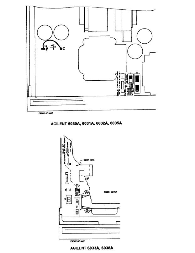
Figure 2-3. Line Voltage Conversion Components
26 Installation

AC Line Impedance Check
The power supply is designed for proper operation with line impedance typically found in ac power lines. However, if the supply is connected to an ac power line having high impedance combined with line voltage near the minimum specified value, (e.g., 104 Vac for nominal 120 Vac), the unit will go out of regulation if it is asked to provide full rated output power. Such a situation might occur if the supply is connected to ac power an extended distance from the main ac distribution terminals and/or if the ac power wires from the main ac distribution terminals are of relatively small gauge.
Measurement of ac line voltage at the supply input terminals typically is not a reliable indication of the actual ac line voltage because of the peak clipping effect of the power supply and the averaging effect of the voltmeter. Symptoms of excessive line impedance may include erratic or no output from the supply and/or inability of the supply to provide full output power. If there is reason to suspect the ac power lines to the supply may have high impedance, perform the following check:
This check should be performed only by service-trained personnel who are aware of the hazards involved (for example, fire and electrical shock). Turn power supply off before making or breaking connections to power supply. Hazardous voltages are present within the unit even when power switch is turned off.
a.Connect a variable load to the supply. Using the OUTPUT ADJUST controls and DISPLAY SETTINGS, set voltage and current (see Section III for detailed description) to maximum rating.
b.Set the load to the maximum rated output current for the power supply (see Table 1-1). The power supply output voltage should be greater than:
65 |
V for Agilent 6030A |
6 V for Agilent 6033A |
8 |
V for Agilent 6031A |
220 V for Agilent 6035A |
22 V for Agilent 6032A |
20 V for Agilent 6038A |
|
c.If the supply voltage is less than specified, perform the power limit calibration given in the Service Manual. If the power limit is calibrated correctly, but the unit still does not provide the required output, then the power supply is not receiving adequate ac line input.
Repackaging For Shipment
To insure safe shipment of the instrument, it is recommended that the package designed for the instrument be used. The original packaging material is reusable. If it is not available, contact your local Agilent Technologies Sales and Support office to obtain the materials. This office will also furnish the address of the nearest service office to which the instrument can be shipped. Be sure to attach a tag to the instrument specifying the owner, model number, full serial number, and service required or a brief description of the trouble.
Rear Panel Screw Sizes and Part Numbers
Refer to the following list if you need to replace any of the rear panel connection hardware. Figure 2-4 identifies the part number location.
Agilent Models 6030A, 6031A, 6032A, 6035A |
|
|
Item |
Description |
Agilent Part number |
ac input cover |
|
5060-3237 |
ac input cover screws |
M4 X 0.7 X 60 mm (qty 4) |
0515-0156 |
ac input barrier block |
3-terminal barrier block |
0360-2217 |
ac input barrier block screws |
8-32 X 5/16 (qty 3) |
included with ac input barrier block |
dc output cover |
|
5040-1626 |
dc output cover screws |
M4 X 0.7 X 10 mm (qty 3) |
0515-0414 (washer 3050-1053) |
control signal barrier block |
6 - terminal barrier block |
0360-2195 |
Installation 27
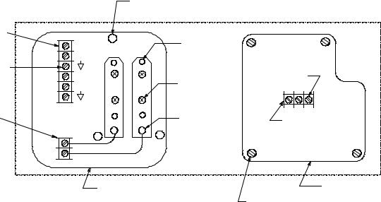
sense barrier block |
2 - terminal barrier block |
0360-2192 |
||
barrier block screws |
M3.5 X 0.6 X 6 mm (qty 8) |
0515-0212 |
||
FLT/INH connector |
4 - terminal removable connector |
1252-1488 |
||
output buss bar screws |
M5 |
X 0.8 X 12 mm |
(qty 4) |
0515-0155 |
output buss bar sense screws |
M2 |
X 0.4 X 8 mm |
(qty 2) |
0515-0212 |
red/black sense wires |
wire kit |
|
5060-2913 |
|
Agilent Model 6033A |
|
|
|
|
Item |
Description |
|
Agilent Part number |
|
barrier block cover |
|
|
|
06023-00009 |
control signal barrier block |
6 - terminal barrier block |
0360-2195 |
||
sense barrier block |
2 - terminal barrier block |
0360-2192 |
||
barrier block screws |
M3.5 X 0.6 X 6 mm (qty 8) |
included with dc barrier blocks |
||
FLT/INH connector |
4 - terminal removable connector |
1252-1488 |
||
dc output cover |
|
|
|
0360-2191 |
dc output cover screws |
M4 |
X 0.7 X 8 mm (qty 2) |
0515-1085 |
|
output buss bar screws (large) |
M4 |
X 0.7 X 8 mm |
(qty 2) |
0515-0885 |
output buss bar screws (small) |
M3 |
X 0.5 X 6 mm |
(qty 2) |
0515-0886 |
sense jumpers |
|
|
|
0360-2190 |
Agilent Model 6038A
Item
barrier block cover
control signal barrier block barrier block screws FLT/INH connector
dc output cover output barrier block output cover screws
output barrier block screws sense jumpers
0360-2195
(8)M3.5x0.6 6mm 0515-0212
0360-2192
+S
-S
SYSTEM MODELS
Description |
|
Agilent Part number |
|
|
|
|
06023-00009 |
6 - terminal barrier block |
0360-2195 |
||
M3.5 X 0.6 X 6 mm (qty 6) |
included with dc barrier block |
||
4 - terminal removable connector |
1252-1488 |
||
|
|
|
0360-2191 |
6 - terminal barrier block |
0360-1833 |
||
M5 X 0.7 X 8 mm (qty 2) |
0515-1085 |
||
M3 X 0.6 X 6 mm (qty 8) |
included with dc barrier blocks |
||
|
|
|
0360-2190 |
|
(3) M4x0.7 10mm |
|
|
|
0515-0414 (screw) |
|
|
|
3050-1053 (washer) |
|
|
A |
|
(4) M4x0.7 35mm |
|
VM |
|
|
|
|
0515-0968 |
|
|
+ |
- |
|
|
|
|
||
IM |
|
|
|
B |
B |
|
|
|
|
|
|
M |
|
|
|
VP |
|
|
(3) 8-32 x 5/16 |
IP |
|
(4) M5x0.8 12mm |
|
|
|
|
|
P |
|
0515-0155 |
|
|
|
|
|
B |
B |
(2) M3x0.5 6mm |
0360-2217 |
|
|||
|
|
||
C |
C |
0515-0642 |
|
|
|
||
A A
Cover 5040-1626 |
Cover 5060-3237 |
|
(4) M4x0.7 x 65mm
0515-2430
Figure 2-4. Part Number Location
28 Installation
3
OPERATING INSTRUCTIONS
Introduction
This section describes the operating controls and indicators, turn-on checkout procedures, and operating procedures and considerations for the power supply. Local (front-panel) and remote (via GP-IB) operation are described separately, but the user should become familiar with both methods of operation. Information in pages 1-43 of this section applies to both local and remote operation.
Standard Commands for Programming Instruments (SCPI) programming is described in Appendix C at the rear of this manual.
Programming examples for specific Agilent Technologies computers are given in Appendix D. More theoretical descriptions regarding the operational features of power supplies in general are given in the DC Power Supply Handbook, Application Note 90B (available at no charge from your local Agilent Technologies Sales Support Office).
Figure 3-1. Front-Panel Controls and Indicators
1 |
|
2 |
|
|
5 |
|
|
6 |
9 |
|
|
$'& 32:(5 6833/< 9$: |
|
|
|
|
|||
|
|
|
|
|
|
|
|
)2/'%$&. |
287387 $'-867 |
|
|
507 |
92/76 |
|
$036 |
',63/$< |
(1$%/(' |
92/7$*( &855(17 |
|
|
/&/ |
|
|
|
|
||||
|
/61 |
|
|
|
|
6(77,1*6 |
|
||
|
|
7/. |
|
|
|
|
|
|
|
|
|
654 |
|
|
|
|
|
293 |
|
|
|
|
|
|
|
|
',63/$< |
$'-867 |
|
|
&9 && 29(55$1*( ',6$%/(' |
29 27 )2/'%$&. (55 25 |
293 |
|
|
||||
|
/,1( |
|
|
|
|
|
|
|
|
|
2 |
21 |
|
|
|
|
|
|
|
|
|
OFF |
|
|
|
|
|
|
|
11 |
|
|
3 |
|
|
4 |
7 |
10 |
8 |
|
|
|
|
|
$ $ $ $ |
|
|||
|
|
|
|
|
2 |
|
5 |
|
|
|
|
|
|
|
$'& 32:(5 6833/< 9$: |
|
|
||
|
|
|
1 |
|
507 |
92/76 |
|
$036 |
|
|
|
|
/&/ |
|
|
|
|
||
|
|
|
|
/61 |
|
|
|
|
|
|
|
|
|
|
|
|
|
|
|
|
|
|
|
|
7/. |
|
|
|
|
|
|
|
|
|
654 |
|
|
|
|
|
|
|
|
',63/$< |
',63/$< |
&9 && 29(55$1*( 29 |
3 |
||
|
|
|
|
|
|
|
|
||
|
|
|
6 |
6(77,1*6 |
293 |
|
|
|
|
|
|
|
|
|
29 27 )2/'%$&. (5525 |
|
|||
|
|
|
|
|
|
4 |
|||
|
|
|
|
|
|
|
|
|
|
|
|
|
7 |
|
|
|
|
|
|
|
|
|
|
/,1( |
293 |
)2/'%$&. |
|
287387 $'-867 |
|
|
|
|
|
21 |
$'-867 |
(1$%/(' |
92/7$*( &855(17 |
|
|
|
|
|
|
2 |
|
|
|
|
|
|
|
|
11 |
|
|
|
|
|
|
|
|
|
|
|
10 |
9 |
|
8 |
|
|
|
|
|
|
|
$ $ |
|
|
|
Operating Instructions 29
Before the instrument is turned on, all protective earth terminals, extension cords, and devices connected to the power supply should be connected to a protective earth ground. Any interruption of the protective earth grounding will cause a potential shock hazard that could result in personal injury.
 This instrument can be damaged by electrostatic discharge into the GP-IB and control connectors, or the switches on the rear panel while the unit is turned on. Do not cause an electrostatic discharge into these connectors and switches (which may occur when they are touched) while the unit is turned on.
Also, consistent with good engineering practice, leads attached to customer accessible signal/monitoring ports should be twisted and shielded to maintain the instruments specified performance.
Controls and Indicators
The front-panel controls and indicators are shown in Figure 3-1 and described in Table 3-1. Table 3-1 also lists the paragraphs, in which, use of the controls and indicators is described.
Output Range For An Autoranging Power Supply
The power supply can operate as a constant voltage (CV) or constant current (CC) source over a wide range of output voltage and current combinations. The specifications table contains a graph showing the overall output range of the power supply. Figure 3-2 shows a rectangular operating locus that is defined by voltage and current settings of the power supply. The point on that locus at which the power supply actually operates is determined by the load resistance. Three loadresistance lines are shown on Figure 3-2. The line representing load resistance A, the highest load resistance shown on the graph, crosses the operating locus at point 1. Point 1 is on the part of the operating locus defined by the voltage setting, so the power supply operates in CV mode.
Figure 3-2. Determining Operating Point
Similarly, the line representing load resistance C, the lowest load resistance shown on the graph, crosses the operating locus at point 3. Point 3 is on the part of the operating locus defined by the current setting, so the power supply operates in CC mode.
30 Operating Instructions
Loading...