


 Loading...
Agilent E5250A
Low Leakage Switch
Mainframe
User’s Guide


 Agilent Technologies
Notices
© Agilent Technologies 1995 - 2008
No part of this manual may be reproduced in any form or by any means (including electronic storage and retrieval or translation into a foreign language) without prior agreement and written consent from Agilent Technologies, Inc. as governed by United States and international copyright laws.
Manual Part Number
E5250-90000
Edition
Edition 1, October 1995
Edition 2, January 1997
Edition 3, August 1997
Edition 4, January 2000
Edition 5, May 2000
Edition 6, January 2001
Edition 7, August 2003
Edition 8, July 2005
Edition 9, May 2008
Agilent Technologies, Inc.
5301 Stevens Creek Blvd
Santa Clara, CA 95051 USA
Warranty
The material contained in this document is provided “as is,” and is subject to being changed, without notice, in future editions. Further, to the maximum extent permitted by applicable law, Agilent disclaims all warranties, either express or implied, with regard to this manual and any information contained herein, including but not limited to the implied warranties of merchantability and fitness for a particular purpose. Agilent shall not be liable for errors or for incidental or consequential damages in connection with the furnishing, use, or performance of this document or of any information contained herein. Should Agilent and the user have a separate written agreement with warranty terms covering the material in this document that conflict with these terms, the warranty terms in the separate agreement shall control.
Technology Licenses
The hardware and/or software described in this document are furnished under a license and may be used or copied only in accordance with the terms of such license.
Restricted Rights Legend
If software is for use in the performance of a U.S. Government prime contract or subcontract, Software is delivered and licensed as “Commercial computer software” as defined in DFAR 252.227-7014 (June 1995), or as a “commercial item” as defined in FAR 2.101(a) or as “Restricted computer software” as defined in FAR 52.227-19 (June 1987) or any equivalent agency regulation or contract clause. Use, duplication or disclosure of Software is subject to Agilent Technologies’ standard commercial license terms, and non-DOD Departments and Agencies of the U.S. Government will receive no greater than Restricted Rights as
defined in FAR 52.227-19(c)(1-2) (June 1987). U.S. Government users will receive no greater than Limited Rights as defined in FAR 52.227-14 (June 1987) or DFAR 252.227-7015 (b)(2) (November 1995), as applicable in any technical data.

|
|
DECLARATION OF CONFORMITY |
|
|
|
According to ISO/IEC Guide 22 and CEN/CENELEC EN 45014 |
|
|
|
|
|
Manufacturer’s Name: |
Agilent Technologies International sarl |
||
Manufacturer’s Address: |
Rue de la Gare 29 |
||
Supplier’s Address: |
CH - 1110 Morges |
||
|
Switzerland |
||
Declares under sole responsibility that the product as originally delivered |
|||
Product Name: |
Low Leakage Switch Mainframe 10x12 Matrix |
||
|
Switch24(8x3)CH Multiplexer |
||
|
24(8x3)CH Multiplexer |
||
Model Number: |
Agilent E5250A |
||
|
Agilent E5252A |
||
|
Agilent E5255A |
||
Product Options: |
This declaration covers all options of the above product(s) |
||
complies with the essential requirements of the following applicable European Directives, and carries the CE marking accordingly:
Low Voltage Directive (73/23/EEC, amended by 93/68/EEC) EMC Directive (89/336/EEC, amended by 93/68/EEC)
and conforms with the following product standards
EMC Standard
IEC 61326:2002 / EN 61326:1997 +A1:1998 +A2:2001 +A3:2003
CISPR 11:1997 / EN 55011:1998
IEC61000-4-2:1995 / EN61000-4-2:1995
IEC 61000-4-3:1995 / EN61000-4-3:1995
IEC 61000-4-4:1995 / EN61000-4-4:1995
IEC 61000-4-5:1995 / EN61000-4-5:1995
IEC 61000-4-6:1996 / EN61000-4-6:1996
IEC 61000-4-11:1994 / EN61000-4-11:1994
Canada: ICES-001:1998
Australia/New Zealand: AS/NZS 2064.1
Limit
Group 1 Class A 4 kV CD, 8 kV AD
3 V/m, 80-1000 MHz
0.5 kV signal lines, 1 kV power lines 0.5 kV line-line, 1 kV line-ground
3 V, 0.15-80 MHz
1 cycle, 100%
|
The product was tested in a typical configuration with Agilent Technologies test systems. |
Safety |
IEC 61010-1:2001 / EN 61010-1:2001 |
|
Canada: CSA C22.2 No. 1010.1:1992, NRTL/C |
Supplementary Information:
This DoC applies to above-listed products placed on the EU market after:
September 26, 2006 |
|
|
Date |
|
Toshiyuki Kawaji |
|
|
QA Manager |
|
|
Agilent Technologies |
For further information, please contact your local Agilent Technologies sales office, agent or distributor,

|
• |
Herstellerbescheinigung |
|
|
GEÄUSCHEMISSION |
|
|
Lpa < 70 dB |
|
|
am Arbeitsplatz |
|
|
normaler Betrieb |
|
|
nach DIN 45635 T. 19 |
|
• |
Manufacturer’s Declaration |
|
|
ACOUSTIC NOISE EMISSION |
|
|
Lpa < 70 dB |
|
|
operator position |
|
|
normal operation |
|
|
per ISO 7779 |
|
This ISM device complies with Canadian ICES-001. |
|
NOTE |
||
|
Cet appareil ISM est conforme ?Hla norme NMB-001 du Canada. |
|
|
|
|
This product complies with the WEEE Directive (2002/96/EC) marking requirements. The affixed label indicates that you must not discard this electrical/ electronic product in domestic household waste.
Product Category: With reference to the equipment types in the WEEE Directive Annex I, this product is classed as a “Monitoring and Control instrumentation” product.
Do not dispose in domestic household waste.
To return unwanted products, contact your local Agilent office, or see
www.agilent.com/environment/product/ for more information.
Microsoft, Windows, Windows NT, Visual C++, and Visual Basic are registered trademarks of Microsoft Corporation. Borland C++ Builder is registered trademark of International, Inc. LabWindows and LabVIEW are registered trademarks of National Instruments Corporation.

|
Safety Summary |
|
The following general safety precautions must be observed during all phases of |
|
operation, service, and repair of this instrument. Failure to comply with these |
|
precautions or with specific warnings elsewhere in this manual may impair the |
|
protections provided by the equipment. In addition, it violates safety standards of |
|
design, manufacture, and intended use of the instrument. Agilent Technologies, Inc. |
|
assumes no liability for customer’s failure to comply with these requirements. |
|
Agilent E5250A complies with INSTALLATION CATEGORY II for mains input |
NOTE |
|
|
and INSTALLATION CATEGORY I for measurement input terminals, and |
|
POLLUTION DEGREE 2 defined in IEC 1010-1. |
|
Agilent E5250A is INDOOR USE products. |
|
• GROUND THE INSTRUMENT |
|
|
|
This is Safety Class I instrument. To minimize shock hazard, the instrument |
|
chassis and cabinet must be connected to an electrical ground. The power |
|
terminal and the power cable must meet International Electrotechnical |
|
Commission (IEC) safety standards. |
|
• DO NOT OPERATE IN AN EXPLOSIVE ATMOSPHERE |
|
Do not operate the instrument in the presence of flammable gases or fumes. |
|
Operation of any electrical instrument in such an environment constitutes a |
|
definite safety hazard. |
|
• KEEP AWAY FROM LIVE CIRCUITS |
|
Operation personnel must not remove instrument covers. Component |
|
replacement and internal adjustments must be made by qualified maintenance |
|
personnel. Do not replace components with power cable connected. Under |
|
certain conditions, dangerous voltages may exist even with the power cable |
|
removed. To avoid injuries, always disconnect power and discharge circuits |
|
before touching them. |
|
• DO NOT SERVICE OR ADJUST ALONE |
|
Do not attempt internal service or adjustment unless another person, capable of |
|
rendering first aid and resuscitation, is present. |

• DO NOT SUBSTITUTE PARTS OR MODIFY INSTRUMENT
|
Because of the danger of introducing additional hazards, do not install substitute |
|
parts or perform any unauthorized modification to the instrument. Return the |
|
instrument to a Agilent Technologies Sales and Service Office for services and |
|
repair to ensure that safety features are maintained. |
|
• DANGEROUS PROCEDURE WARNINGS |
|
Warnings, such as example below, precede potentially dangerous procedures |
|
throughout this manual. Instructions contained in the warnings must be |
|
followed. |
|
Dangerous Voltage, capable of causing death, are present in this instrument. |
WARNING |
|
|
Use extreme caution when handling, testing, and adjusting. |

Safety Symbols
The general definitions of safety symbols used on equipment or in manuals are listed below.
Instruction manual symbol: the product will be marked with this symbol when it is necessary for the user to refer to the instruction manual in order to protect against damage to the instrument.
Indicates dangerous voltage and potential for electrical shock. Do not touch terminals that have this symbol when insrument is on.
Affixed to product containing static sensitive devices--use anti-static handling procedures to prevent electrostatic discharge damage to component.
Protective conductor terminal. For protection against electrical shock in case of a fault. Used with field wiring terminals to indicate the terminal which must be connected to ground before operating equipment.
Frame or chassis terminal. A connection to the frame (chassis) of the equipment which normally includes all exposed metal structures.
|
Indicates earth (ground) terminal. |
|
Alternating current. |
|
Direct current. |
|
ON (Supply). |
|
OFF (Supply). |
|
STANDBY (Supply). |
CAT 1 |
Means INSTALLATION CATEGORY I. Measurement terminals on the rear panel |
|
comply with INSTALLATION CATEGORY I. |
|
The warning sign denotes a hazard. It calls attention to a procedure, practice, |
WARNING |
|
|
condition or the like, which, if not correctly performed or adhered to, could result in |
|
injury or death to personal. |
|
The caution sign denotes a hazard. It calls attention to an operating procedure, |
|
|
CAUTION |
|
|
practice, condition or the like, which, if not correctly performed or adhered to, could |
|
result in damage to or destruction of part or all of the product. |
|
|

In This Manual
This manual is a user’s guide for Agilent E5250A, and consists of the following chapters:
•Introduction
Provides an overview of the E5250A Low Leakage Switch Mainframe, E5252A 10×12 Matrix Switch, and E5255A 24 (8×3) Channel Multiplexer.
•Installation
Describes requirements to install the E5250A and tasks for installation.
•Executing Self-Test and Leak Test
Describes how to execute the three Self-Test items (Controller Test, Front Panel Interface Test, and Relay Test) and the Leak Test.
•Setting up Measurement Environment
Explains how to connect your instruments to the E5250A input, and how to connect the E5250A output to your wafer prober or test fixture.
•Controlling the E5250A
Introduces several methods for controlling the E5250A, gives basic information for controlling the relay switches on the plug-in cards, and describes how to use Virtual Front Panel (VFP) utility furnished with the E5250A.
•Programming the E5250A
Describes how to create programs that contain SCPI commands to control the E5250A.
•Command Reference
Describes the SCPI commands available to operate the E5250A via GPIB interface and the status reporting structure.
•VXIplug&play Driver
Introduces the VXIplug&play driver available for the E5250A.
•Executing Sample Programs
Explains how to execute and modify the sample programs stored in the program disk that is furnished with the E5250A.
•Specifications
Lists specifications, typical data, supplemental data, and reference data for the E5250A, E5252A, and E5255A.
•Error Messages
Lists and describes the error messages for the E5250A.
•SCPI Command Summary
This is a quick reference for the SCPI subsystem commands available for the E5250A.
Text Conventions
The following text conventions are used in this manual:
Represents text that appears on screen of the controller.
Refers to a related document, or is used for emphasis.
Contents
1. Introduction
Agilent E5250A Product Description . . . . . . . . . . . . . . . . . . . . . . . . . . . . . . . . . . 1-3 Front Panel Tour . . . . . . . . . . . . . . . . . . . . . . . . . . . . . . . . . . . . . . . . . . . . . . . . 1-4 Rear Panel Tour . . . . . . . . . . . . . . . . . . . . . . . . . . . . . . . . . . . . . . . . . . . . . . . . . 1-4  . . . . . . . . . . . . . . . . . . . . . . . . . . . . . . . . . . . . . . . . . . . . . . . . . . . . . . . . . . . . . 1-5 Agilent E5252A Product Description . . . . . . . . . . . . . . . . . . . . . . . . . . . . . . . . . . 1-6
  . . . . . . . . . . . . . . . . . . . . . . . . . . . . . . . . . . . . . . . . . . . . . . . . . . . . . . . . . . . . . 1-7 Agilent E5255A Product Description . . . . . . . . . . . . . . . . . . . . . . . . . . . . . . . . . . 1-8
  . . . . . . . . . . . . . . . . . . . . . . . . . . . . . . . . . . . . . . . . . . . . . . . . . . . . . . . . . . . . 1-11 Options and Accessories . . . . . . . . . . . . . . . . . . . . . . . . . . . . . . . . . . . . . . . . . . . 1-12
2. Installation
 . . . . . . . . . . . . . . . . . . . . . . . . . . . . . . . . . . . . . . . . . . . . . . . . . . . . . . . . . . . . . 2-2
To Inspect the E5250A and Accessories . . . . . . . . . . . . . . . . . . . . . . . . . . . . . . . . 2-3
Requirements . . . . . . . . . . . . . . . . . . . . . . . . . . . . . . . . . . . . . . . . . . . . . . . . . . . . 2-4
Power Requirements . . . . . . . . . . . . . . . . . . . . . . . . . . . . . . . . . . . . . . . . . . . . . 2-4
Power Cable . . . . . . . . . . . . . . . . . . . . . . . . . . . . . . . . . . . . . . . . . . . . . . . . . . . . 2-4
Operating Environment . . . . . . . . . . . . . . . . . . . . . . . . . . . . . . . . . . . . . . . . . . . 2-6
Storage and Shipping Environment . . . . . . . . . . . . . . . . . . . . . . . . . . . . . . . . . . 2-6
Installing the E5250A . . . . . . . . . . . . . . . . . . . . . . . . . . . . . . . . . . . . . . . . . . . . . . 2-7  . . . . . . . . . . . . . . . . . . . . . . . . . . . . . . . . . . . . . . . . . . . . . . . . . . . . . . . . . . . . . 2-7 To Install Plug-in Card . . . . . . . . . . . . . . . . . . . . . . . . . . . . . . . . . . . . . . . . . . . . 2-8 To Install Blank Panel . . . . . . . . . . . . . . . . . . . . . . . . . . . . . . . . . . . . . . . . . . . . 2-9 To Configure E5255A . . . . . . . . . . . . . . . . . . . . . . . . . . . . . . . . . . . . . . . . . . . 2-10
  . . . . . . . . . . . . . . . . . . . . . . . . . . . . . . . . . . . . . . . . . . . . . . . . . . . . . . . . . . . . 2-11
  . . . . . . . . . . . . . . . . . . . . . . . . . . . . . . . . . . . . . . . . . . . . . . . . . . . . . . . . . . . . 2-12 E5255A Configuration Examples. . . . . . . . . . . . . . . . . . . . . . . . . . . . . . . . . . . 2-13 To Set GPIB Address . . . . . . . . . . . . . . . . . . . . . . . . . . . . . . . . . . . . . . . . . . . . 2-17 To Connect GPIB Cable . . . . . . . . . . . . . . . . . . . . . . . . . . . . . . . . . . . . . . . . . 2-17
Agilent E5250A User’s Guide, Edition 9 |
Contents - 1 |

Contents
Maintenance. . . . . . . . . . . . . . . . . . . . . . . . . . . . . . . . . . . . . . . . . . . . . . . . . . . . . 2-18
Performance Verification . . . . . . . . . . . . . . . . . . . . . . . . . . . . . . . . . . . . . . . . . 2-18
Cleaning . . . . . . . . . . . . . . . . . . . . . . . . . . . . . . . . . . . . . . . . . . . . . . . . . . . . . 2-18
3. Executing Self-Test and Leak Test
Executing Self-Test . . . . . . . . . . . . . . . . . . . . . . . . . . . . . . . . . . . . . . . . . . . . . . . . 3-3 To Execute Self-Test (Standalone) . . . . . . . . . . . . . . . . . . . . . . . . . . . . . . . . . . 3-4 To Execute Self-Test using External Controller . . . . . . . . . . . . . . . . . . . . . . . . 3-6
Using the Self-Test Utility . . . . . . . . . . . . . . . . . . . . . . . . . . . . . . . . . . . . . . . . . 3-10
Requirements . . . . . . . . . . . . . . . . . . . . . . . . . . . . . . . . . . . . . . . . . . . . . . . . . 3-10
To Start the Self-Test Utility . . . . . . . . . . . . . . . . . . . . . . . . . . . . . . . . . . . . . . 3-11
To Execute Self-Test . . . . . . . . . . . . . . . . . . . . . . . . . . . . . . . . . . . . . . . . . . . . 3-12
To Execute Leak Test . . . . . . . . . . . . . . . . . . . . . . . . . . . . . . . . . . . . . . . . . . . 3-15
4. Setting up Measurement Environment
Connector Plates . . . . . . . . . . . . . . . . . . . . . . . . . . . . . . . . . . . . . . . . . . . . . . . . . . 4-3
Connector Plates for the E5252A. . . . . . . . . . . . . . . . . . . . . . . . . . . . . . . . . . . . 4-3
Connector Plates for E5255A . . . . . . . . . . . . . . . . . . . . . . . . . . . . . . . . . . . . . . 4-3
Blank Plate . . . . . . . . . . . . . . . . . . . . . . . . . . . . . . . . . . . . . . . . . . . . . . . . . . . . . 4-4
Connecting 8-Channel Shielded Coaxial Cable . . . . . . . . . . . . . . . . . . . . . . . . . . 4-5  . . . . . . . . . . . . . . . . . . . . . . . . . . . . . . . . . . . . . . . . . . . . . . . . . . . . . . . . . . . . . 4-5
Mounting Connectors Directly . . . . . . . . . . . . . . . . . . . . . . . . . . . . . . . . . . . . . . . 4-6 To Make Interlock Circuit . . . . . . . . . . . . . . . . . . . . . . . . . . . . . . . . . . . . . . . . . 4-8 To Connect Connectors to DUT . . . . . . . . . . . . . . . . . . . . . . . . . . . . . . . . . . . 4-13
Connecting the E5250A Input . . . . . . . . . . . . . . . . . . . . . . . . . . . . . . . . . . . . . . 4-15 To Connect Instruments to Input Connectors . . . . . . . . . . . . . . . . . . . . . . . . . 4-15 To Connect Bias Source to the E5255A Bias Input . . . . . . . . . . . . . . . . . . . . 4-18 To Connect GNDU to the E5250A Input . . . . . . . . . . . . . . . . . . . . . . . . . . . . 4-18
Connecting the E5250A Output . . . . . . . . . . . . . . . . . . . . . . . . . . . . . . . . . . . . . 4-20
Contents - 2 |
Agilent E5250A User’s Guide, Edition 9 |

Contents
To Connect the E5252A Output . . . . . . . . . . . . . . . . . . . . . . . . . . . . . . . . . . . 4-20 To Connect the E5255A Output . . . . . . . . . . . . . . . . . . . . . . . . . . . . . . . . . . . 4-22
Measurement Cable Length . . . . . . . . . . . . . . . . . . . . . . . . . . . . . . . . . . . . . . . . 4-23
5. Controlling the E5250A
Methods for Controlling the E5250A . . . . . . . . . . . . . . . . . . . . . . . . . . . . . . . . . . 5-3 Creating Your Own Program . . . . . . . . . . . . . . . . . . . . . . . . . . . . . . . . . . . . . . . 5-3 Modifying a Sample Program . . . . . . . . . . . . . . . . . . . . . . . . . . . . . . . . . . . . . . 5-4 Using the Virtual Front Panel (VFP) Utility . . . . . . . . . . . . . . . . . . . . . . . . . . . 5-4
Switch Control Basics . . . . . . . . . . . . . . . . . . . . . . . . . . . . . . . . . . . . . . . . . . . . . . 5-5
Channel List and Channel Configuration . . . . . . . . . . . . . . . . . . . . . . . . . . . . . 5-6
Connection Rule . . . . . . . . . . . . . . . . . . . . . . . . . . . . . . . . . . . . . . . . . . . . . . . . 5-9
Connection Sequence . . . . . . . . . . . . . . . . . . . . . . . . . . . . . . . . . . . . . . . . . . . 5-10
Bias Mode . . . . . . . . . . . . . . . . . . . . . . . . . . . . . . . . . . . . . . . . . . . . . . . . . . . . 5-11
Couple Port . . . . . . . . . . . . . . . . . . . . . . . . . . . . . . . . . . . . . . . . . . . . . . . . . . . 5-13
E5252A Channel List . . . . . . . . . . . . . . . . . . . . . . . . . . . . . . . . . . . . . . . . . . . 5-15
E5255A Channel List . . . . . . . . . . . . . . . . . . . . . . . . . . . . . . . . . . . . . . . . . . . 5-19
Using Virtual Front Panel Utility . . . . . . . . . . . . . . . . . . . . . . . . . . . . . . . . . . . . 5-25 Functions of Virtual Front Panel Utility . . . . . . . . . . . . . . . . . . . . . . . . . . . . . 5-26 Requirements . . . . . . . . . . . . . . . . . . . . . . . . . . . . . . . . . . . . . . . . . . . . . . . . . . 5-27 Starting the Virtual Front Panel Utility . . . . . . . . . . . . . . . . . . . . . . . . . . . . . . 5-27 Confirming the E5250A Card Configurations . . . . . . . . . . . . . . . . . . . . . . . . 5-28 Changing the VFP Setup Mode . . . . . . . . . . . . . . . . . . . . . . . . . . . . . . . . . . . . 5-29 Defining Labels for the E5250A Input Ports . . . . . . . . . . . . . . . . . . . . . . . . . . 5-31 Making Connections and Changing the Setup Data . . . . . . . . . . . . . . . . . . . . 5-33 Saving/Loading the Setup Data . . . . . . . . . . . . . . . . . . . . . . . . . . . . . . . . . . . . 5-42
6. Programming the E5250A
SCPI Programming Basics . . . . . . . . . . . . . . . . . . . . . . . . . . . . . . . . . . . . . . . . . . 6-3
SCPI Command Hierarchy . . . . . . . . . . . . . . . . . . . . . . . . . . . . . . . . . . . . . . . . 6-4
Agilent E5250A User’s Guide, Edition 9 |
Contents - 3 |

Contents
Controlling E5250A by Using HP BASIC . . . . . . . . . . . . . . . . . . . . . . . . . . . . 6-5
Creating a Control Program . . . . . . . . . . . . . . . . . . . . . . . . . . . . . . . . . . . . . . . . . 6-6 Defining Channel Configuration Mode . . . . . . . . . . . . . . . . . . . . . . . . . . . . . . 6-8 Defining Connection Rule . . . . . . . . . . . . . . . . . . . . . . . . . . . . . . . . . . . . . . . . 6-8 Defining Connection Sequence . . . . . . . . . . . . . . . . . . . . . . . . . . . . . . . . . . . . . 6-9 Using Bias Mode . . . . . . . . . . . . . . . . . . . . . . . . . . . . . . . . . . . . . . . . . . . . . . . 6-10 Using Couple Port (for E5252A only) . . . . . . . . . . . . . . . . . . . . . . . . . . . . . . 6-11 Controlling Relay Switching . . . . . . . . . . . . . . . . . . . . . . . . . . . . . . . . . . . . . . 6-12
Programming Examples . . . . . . . . . . . . . . . . . . . . . . . . . . . . . . . . . . . . . . . . . . . 6-13
Channel Creation Example . . . . . . . . . . . . . . . . . . . . . . . . . . . . . . . . . . . . . . . 6-14
Bias Mode Example . . . . . . . . . . . . . . . . . . . . . . . . . . . . . . . . . . . . . . . . . . . . 6-16
Couple Port Example . . . . . . . . . . . . . . . . . . . . . . . . . . . . . . . . . . . . . . . . . . . 6-19
Using the VFP Data Upload Library . . . . . . . . . . . . . . . . . . . . . . . . . . . . . . . . . 6-22
VFP Data Upload Library . . . . . . . . . . . . . . . . . . . . . . . . . . . . . . . . . . . . . . . . 6-23
Programming Example . . . . . . . . . . . . . . . . . . . . . . . . . . . . . . . . . . . . . . . . . . 6-25
Before Executing Your Program . . . . . . . . . . . . . . . . . . . . . . . . . . . . . . . . . . . 6-26
Error Messages . . . . . . . . . . . . . . . . . . . . . . . . . . . . . . . . . . . . . . . . . . . . . . . . 6-27
Using the Capacitance Compensation Routine . . . . . . . . . . . . . . . . . . . . . . . . . |
6-28 |
Capacitance Compensation Routine . . . . . . . . . . . . . . . . . . . . . . . . . . . . . . . . |
6-29 |
Required Conditions . . . . . . . . . . . . . . . . . . . . . . . . . . . . . . . . . . . . . . . . . . . . |
6-30 |
Programming Example . . . . . . . . . . . . . . . . . . . . . . . . . . . . . . . . . . . . . . . . . . |
6-32 |
Before Executing Your Program . . . . . . . . . . . . . . . . . . . . . . . . . . . . . . . . . . . |
6-32 |
Error Messages . . . . . . . . . . . . . . . . . . . . . . . . . . . . . . . . . . . . . . . . . . . . . . . . |
6-32 |
7. Command Reference |
|
Common Commands . . . . . . . . . . . . . . . . . . . . . . . . . . . . . . . . . . . . . . . . . . . . . |
. 7-4 |
:DIAGnostic Subsystem . . . . . . . . . . . . . . . . . . . . . . . . . . . . . . . . . . . . . . . . . . . 7-15
:ROUTe Subsystem . . . . . . . . . . . . . . . . . . . . . . . . . . . . . . . . . . . . . . . . . . . . . . 7-20
:SYSTem Subsystem . . . . . . . . . . . . . . . . . . . . . . . . . . . . . . . . . . . . . . . . . . . . . 7-42
Contents - 4 |
Agilent E5250A User’s Guide, Edition 9 |

Contents
Status Reporting Structure . . . . . . . . . . . . . . . . . . . . . . . . . . . . . . . . . . . . . . . . . 7-48
Status Reporting Structure . . . . . . . . . . . . . . . . . . . . . . . . . . . . . . . . . . . . . . . . 7-48
Status Byte Register . . . . . . . . . . . . . . . . . . . . . . . . . . . . . . . . . . . . . . . . . . . . 7-50
Service Request Enable Register . . . . . . . . . . . . . . . . . . . . . . . . . . . . . . . . . . . 7-52
Standard Event Status Register . . . . . . . . . . . . . . . . . . . . . . . . . . . . . . . . . . . . 7-53
Standard Event Status Enable Register . . . . . . . . . . . . . . . . . . . . . . . . . . . . . . 7-54
Output Queue . . . . . . . . . . . . . . . . . . . . . . . . . . . . . . . . . . . . . . . . . . . . . . . . . . 7-55
8. VXIplug&play Driver
System Requirements. . . . . . . . . . . . . . . . . . . . . . . . . . . . . . . . . . . . . . . . . . . . . . . 8-3
Installing VXIplug&play Driver . . . . . . . . . . . . . . . . . . . . . . . . . . . . . . . . . . . . . . 8-4
Driver Functions . . . . . . . . . . . . . . . . . . . . . . . . . . . . . . . . . . . . . . . . . . . . . . . . . . 8-5
9. Executing Sample Programs
Vth and Capacitance Measurement Program . . . . . . . . . . . . . . . . . . . . . . . . . . . . 9-3 Introduction . . . . . . . . . . . . . . . . . . . . . . . . . . . . . . . . . . . . . . . . . . . . . . . . . . . . 9-3 Setting up the Measurement Environment . . . . . . . . . . . . . . . . . . . . . . . . . . . . 9-7 Executing the Program . . . . . . . . . . . . . . . . . . . . . . . . . . . . . . . . . . . . . . . . . . . 9-9 Modifying the Program . . . . . . . . . . . . . . . . . . . . . . . . . . . . . . . . . . . . . . . . . . 9-11
HCI Measurement Program . . . . . . . . . . . . . . . . . . . . . . . . . . . . . . . . . . . . . . . . 9-17 Introduction . . . . . . . . . . . . . . . . . . . . . . . . . . . . . . . . . . . . . . . . . . . . . . . . . . . 9-17 Adding the Bias Source Control Routine . . . . . . . . . . . . . . . . . . . . . . . . . . . . 9-23 Setting up the Measurement Environment . . . . . . . . . . . . . . . . . . . . . . . . . . . 9-24 Executing the Program . . . . . . . . . . . . . . . . . . . . . . . . . . . . . . . . . . . . . . . . . . 9-27 Modifying the Program . . . . . . . . . . . . . . . . . . . . . . . . . . . . . . . . . . . . . . . . . . 9-35
10.Specifications
11.Error Messages
Agilent E5250A User’s Guide, Edition 9 |
Contents - 5 |

Contents
12. SCPI Command Summary
Contents - 6 |
Agilent E5250A User’s Guide, Edition 9 |

1 Introduction

Introduction
This chapter gives an overview of Agilent E5250A, E5252A, and E5255A.
•“Agilent E5250A Product Description”
•“Agilent E5252A Product Description”
•“Agilent E5255A Product Description”
•“Options and Accessories”
1-2 |
Agilent E5250A User’s Guide, Edition 9 |

Introduction
Agilent E5250A Product Description
Agilent E5250A Product Description
Agilent E5250A Low Leakage Switch Mainframe is a computer-controlled switching matrix mainframe designed for semiconductor dc characteristics measurement applications. The E5250A has four slots for installing the modules (plug-in cards) listed in Table 1-1.
These cards can be used in various switching matrix configurations in the E5250A. For example, using four E5252As, you can configure a maximum 10-input 48-output switching matrix, or using four E5255As, you can configure a maximum 2-input × 96-output multiplexer.
Table 1-1 |
Available Plug-in Cards for E5250A |
|
|
|
|
|
|
|
|
|||||||||||||||
|
|
|
|
|
|
|
|
|
|
|
|
|
|
|
|
|
|
|
|
|
|
|
|
|
|
|
|
|
|
|
|
|
|
|
|
|
|
Model No. |
Description |
|
|
|
|
|
|
|
|
||
|
|
|
|
|
|
|
|
|
|
|
|
|
|
|
|
|
|
|
|
|
|
|
|
|
|
|
|
|
|
|
|
|
|
|
|
|
|
E5252A |
10×12 Matrix Switch |
|
|
|
|
|
|
|
|
||
|
|
|
|
|
|
|
|
|
|
|
|
|
|
|
|
|
|
|
|
|
|
|
|
|
|
|
|
|
|
|
|
|
|
|
|
|
|
E5255A |
24 (8×3) Channel Multiplexer |
|
|
|
|
|
|
|
|
||
|
|
|
|
|
|
|
|
|
|
|
|
|
|
|
|
|
|
|
|
|
|
|
|
|
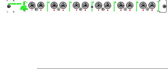
Figure 1-1 |
E5250A Front Panel |
|
|
|
|
|
|
|
|
|
||||||||||||||
|
|
|
|
|
|
|
|
|
|
|
|
|
|
|
|
|
|
|
|
|
|
|
|
|
|
|
|
|
|
|
|
|
|
|
|
|
|
|
|
|
|
|
|
|
|
|
|
|
|
|
|
|
|
|
|
|
|
|
|
|
|
|
|
|
|
|
|
|
|
|
|
|
|
|
|
|
|
|
|
|
|
|
|
|
|
|
|
|
|
|
|
|
|
|
|
|
|
|
|
|
|
|
|
|
|
|
|
|
|
|
|
|
|
|
|
|
|
|
|
|
|
|
|
|
|
|
|
|
|
|
|
|
|
|
|
|
|
|
|
|
|
|
|
|
|
|
|
|
|
|
|
|
|
|
|
|
|
|
|
|
|
|
|
|
|
|
|
|
|
|
|
|
|
|
|
|
|
|
|
|
|
|
|
|
|
|
|
|
|
|
|
|
|
|
|
|
|
|
|
|
|
|
|
|
|
|
|
|
|
|
|
|
|
|
|
|
|
|
|
|
|
|
|
|
|
|
|
|
|
|
|
|
|
|
|
|
|
|
|
|
|
|
|
|
|
|
|
|
|
|
|
|
|
|
|
|
|
|
|
|
|
|
|
|
|
|
|
|
|
|
|
|
|
|
|
|
|
|
|
|
|
|
|
|
|
|
|
|
|
|
|
|
|
|
|
|
|
|
|
|
|
|
|
|
|
|
|
|
|
|
|
|
|
|
|
|
|
|
|
|
|
|
|
|
|
|
|
|
|
|
|
|
|
|
|
|
|
|
|
|
|
|
|
|
|
|
|
|
|
Agilent E5250A User’s Guide, Edition 9 |
1-3 |

Introduction
Agilent E5250A Product Description
Front Panel Tour
The E5250A has 2 hard keys and 4 LED indicators on the front panel as shown in Figure 1-1.
LINE key |
Used to turn the E5250A on or off. |
Line LED |
Turns on when the E5250A is turned on. |
Local/Self Test key |
If "Remote" LED is on, pressing this key releases the |
|
E5250A from remote GPIB control by an external controller. |
|
If "Remote" LED is off, pressing this key executes the Relay |
|
Test. Before pressing this key, make sure the Relay Test |
|
Adapter is connected. For details of Relay Test, refer to |
|
Chapter 3. During Relay Test execution, the LED in this key |
|
is ON. |
Remote LED |
Turns on when the E5250A is in the GPIB remote status. |
System Fail LED |
Turns on if system error occurs in the E5250A. Contact your |
|
nearest Agilent Technologies Service Center. |
Fail LED |
Turns on if the E5250A fails Self-test (including Relay Test). |
|
If this LED turns on after executing Relay Test, a plug-in |
|
card may be defective. And if this LED turns on after turning |
|
the E5250A on again, the E5250A is defective. If so, contact |
|
your nearest Agilent Technologies Service Center. |
Rear Panel Tour
Rear panel of the E5250A is shown in Figure 1-2. The E5250A has 4 slots for installing plug-in cards, and 10 input connectors for connecting measurement cables from instruments.
SMU INPUT SMU INPUT connectors are for semiconductor dc characteristics measurements.
The E5250A has six SMU INPUT ports, which are triaxial type connectors. The connectors can also be used for a maximum three Kelvin connection inputs by coupling two ports as follows:
•SMU INPUT 1 and 2
•SMU INPUT 3 and 4
•SMU INPUT 5 and 6
1-4 |
Agilent E5250A User’s Guide, Edition 9 |
|
|
|
|
|
|
|
|
|
|
|
|
|
|
|
|
|
|
|
|
|
|
|
|
|
|
|
|
|
|
|
|
|
|
|
|
|
|
|
|
|
|
|
Introduction |
||||||||||||||||
|
|
|
|
|
|
|
|
|
|
|
|
|
|
|
|
|
|
|
|
|
|
|
|
Agilent E5250A Product Description |
|||||||||||||||||||||||||||||||||||
|
|
|
|
|
|
|
|
|
|
|
|
AUX INPUT |
AUX INPUT connectors are for C-V measurements, pulse |
||||||||||||||||||||||||||||||||||||||||||||||
|
|
|
|
|
|
|
|
|
|
|
|
|
|
|
input, and so on. |
||||||||||||||||||||||||||||||||||||||||||||
|
|
|
|
|
|
|
|
|
|
|
|
|
|
|
The E5250A has 4 AUX INPUT ports: HF1, HF2, CV1, CV2. |
||||||||||||||||||||||||||||||||||||||||||||
|
|
|
|
|
|
|
|
|
|
|
|
|
|
|
These are BNC type connectors. |
||||||||||||||||||||||||||||||||||||||||||||
|
|
|
|
|
|
|
|
|
|
|
|
|
|
|
The AUX INPUT connectors are used only with the E5252A |
||||||||||||||||||||||||||||||||||||||||||||
|
|
|
|
|
|
|
|
|
|
|
|
|
|
|
and are not used with the E5255A. |
||||||||||||||||||||||||||||||||||||||||||||
|
|
|
|
|
|
|
|
|
|
|
|
The maximum measurement voltage that can be applied to any input terminal is |
|||||||||||||||||||||||||||||||||||||||||||||||
CAUTION |
|
||||||||||||||||||||||||||||||||||||||||||||||||||||||||||
|
|
|
|
|
|
|
|
|
|
|
|
±200 Vdc. The maximum measurement current is 1 Adc at ±200 Vdc. The |
|||||||||||||||||||||||||||||||||||||||||||||||
|
|
|
|
|
|
|
|
|
|
|
|
maximum voltage that can be applied between input terminals is 300 Vdc. Do not |
|||||||||||||||||||||||||||||||||||||||||||||||
|
|
|
|
|
|
|
|
|
|
|
|
apply an input signal over these limits to the E5250A inputs. If you do, the E5250A |
|||||||||||||||||||||||||||||||||||||||||||||||
|
|
|
|
|
|
|
|
|
|
|
|
will be damaged. |
|
|
|
|
|
|
|
|
|
|
|
|
|
|
|
|
|
|
|
|
|
|
|
|
|
|
|
|
|
|
|
|
|
|
|
|
|
|
|
|
|
|
|
|
|
||
|
|
|
|
|
|
|
|
|
|
|
|
If you use a bias source that has current limit capability, set the bias source current |
|||||||||||||||||||||||||||||||||||||||||||||||
|
|
|
|
|
|
|
|
|
|
|
|
limit to less than 1 Adc. |
|||||||||||||||||||||||||||||||||||||||||||||||
|
|
|
|
|
|
|
|
|
|
|
|
|
|
|
|
|
|
|
|
|
|
|
|
|
|
|
|
|
|
|
|
|
|
|
|
|
|
|
|
|
|
|
|
|
|
|
|
|
|
|
|
|
|
|
|
|
|
|
|
Figure 1-2 |
|
E5250A Rear Panel |
|||||||||||||||||||||||||||||||||||||||||||||||||||||||||
|
|
|
|
|
|
|
|
|
|
|
|
|
|
|
|
|
|
|
|
|
|
|
|
|
|
|
|
|
|
|
|
|
|
|
|
|
|
|
|
|
|
|
|
|
|
|
|
|
|
|
|
|
|
|
|
|
|
|
|
|
|
|
|
|
|
|
|
|
|
|
|
|
|
|
|
|
|
|
|
|
|
|
|
|
|
|
|
|
|
|
|
|
|
|
|
|
|
|
|
|
|
|
|
|
|
|
|
|
|
|
|
|
|
|
|
|
|
|
|
|
|
|
|
|
|
|
|
|
|
|
|
|
|
|
|
|
|
|
|
|
|
|
|
|
|
|
|
|
|
|
|
|
|
|
|
|
|
|
|
|
|
|
|
|
|
|
|
|
|
|
|
|
|
|
|
|
|
|
|
|
|
|
|
|
|
|
|
|
|
|
|
|
|
|
|
|
|
|
|
|
|
|
|
|
|
|
|
|
|
|
|
|
|
|
|
|
|
|
|
|
|
|
|
|
|
|
|
|
|
|
|
|
|
|
|
|
|
|
|
|
|
|
|
|
|
|
|
|
|
|
|
|
|
|
|
|
|
|
|
|
|
|
|
|
|
|
|
|
|
|
|
|
|
|
|
|
|
|
|
|
|
|
|
|
|
|
|
|
|
|
|
|
|
|
|
|
|
|
|
|
|
|
|
|
|
|
|
|
|
|
|
|
|
|
|
|
|
|
|
|
|
|
|
|
|
|
|
|
|
|
|
|
|
|
|
|
|
|
|
|
|
|
|
|
|
|
|
|
|
|
|
|
|
|
|
|
|
|
|
|
|
|
|
|
|
|
|
|
|
|
|
|
|
|
|
|
|
|
|
|
|
|
|
|
|
|
|
|
|
|
|
|
|
|
|
|
|
|
|
|
|
|
|
|
|
|
|
|
|
|
|
|
|
|
|
|
|
|
|
|
|
|
|
|
|
|
|
|
|
|
|
|
|
|
|
|
|
|
|
|
|
|
|
|
|
|
|
|
|
|
|
|
|
|
|
|
|
|
|
|
|
|
|
|
|
|
|
|
|
|
|
|
|
|
|
|
|
|
|
|
|
|
|
|
|
|
|
|
|
|
|
|
|
|
|
|
|
|
|
|
|
|
|
|
|
|
|
|
|
|
|
|
|
|
|
|
|
|
|
|
|
|
|
|
|
|
|
|
|
|
|
|
|
|
|
|
|
|
|
|
|
|
|
|
|
|
|
|
|
|
|
|
|
|
|
|
|
|
|
|
|
|
|
|
|
|
|
|
|
|
|
|
|
|
|
|
|
|
|
|
|
|
|
|
|
|
|
|
|
|
|
|
|
|
|
|
|
|
|
|
|
|
|
|
|
|
|
|
|
|
|
|
|
|
|
|
|
|
|
|
|
|
|
|
|
|
|
|
|
|
|
|
|
|
|
|
|
|
|
|
|
|
|
|
|
|
|
|
|
|
|
|
|
|
|
|
|
|
|
|
|
|
|
|
|
|
|
|
|
|
|
|
|
|
|
|
|
|
|
|
|
|
|
|
|
|
|
|
|
|
|
|
|
|
|
|
|
|
|
|
|
|
|
|
|
|
|
|
|
|
|
|
|
|
|
|
|
|
|
|
|
|
|
|
|
|
|
|
|
|
|
|
|
|
|
|
|
|
|
|
|
|
|
|
|
|
|
|
|
|
|
|
|
|
|
|
|
|
|
|
|
|
|
|
|
|
|
|
|
|
|
|
|
|
|
|
|
|
|
|
|
|
|
|
|
|
|
|
|
|
|
|
|
|
|
|
|
|
|
|
|
|
|
|
|
|
|
|
|
|
|
|
|
|
|
|
|
|
|
|
|
|
|
|
|
|
|
|
|
|
|
|
|
|
|
|
|
|
|
|
|
|
|
|
|
|
|
|
|
|
|
|
|
|
|
|
|
|
|
|
|
|
|
|
|
|
|
|
|
|
|
|
|
|
|
|
|
|
|
|
|
|
|
|
|
|
|
|
|
|
|
|
|
|
|
|
|
|
|
|
|
|
|
|
|
|
|
|
|
|
|
|
|
|
|
|
|
|
|
|
|
|
|
|
|
|
|
|
|
|
|
|
|
|
|
|
|
|
|
|
|
|
|
|
|
|
|
|
|
|
|
|
|
|
|
|
|
|
|
|
|
|
|
|
|
|
|
|
|
|
|
|
|
|
|
|
|
|
|
|
|
|
|
|
|
|
|
|
|
|
|
|
|
|
|
|
|
|
|
|
|
|
|
|
|
|
|
|
|
|
|
|
|
|
|
|
|
|
|
|
|
|
|
|
|
|
|
|
|
|
|
|
|
|
|
|
|
|
|
|
|
|
|
|
|
|
|
|
|
|
|
|
|
|
|
|
|
|
|
|
|
|
|
|
|
|
|
|
|
|
|
|
|
|
|
|
|
|
|
|
|
|
|
|
|
|
|
|
|
|
|
|
|
|
|
|
|
|
|
|
|
|
|
|
|
|
|
|
|
|
|
|
|
|
|
|
|
|
|
|
|
|
|
|
|
|
|
|
|
|
|
|
|
|
|
|
|
|
|
|
|
|
|
|
|
|
|
|
|
|
|
|
|
|
|
|
|
|
|
|
|
|
|
|
|
|
|
|
|
|
|
|
|
|
|
|
|
|
|
|
|
|
|
|
|
|
|
|
|
|
|
|
|
|
|
|
|
|
|
|
|
|
|
|
|
|
|
|
|
|
|
|
|
|
|
|
|
|
|
|
|
|
|
|
|
|
|
|
|
|
|
|
|
|
|
|
|
|
|
|
|
|
|
|
|
|
|
|
|
|
|
|
|
|
|
|
|
|
|
Agilent E5250A User’s Guide, Edition 9 |
1-5 |

Introduction
Agilent E5252A Product Description
Agilent E5252A Product Description
The E5252A 10×12 Matrix Switch is a 10-input to 12-output switching matrix card for the E5250A. The E5252A is designed for semiconductor dc parametric measurement applications that need to switch some instruments connected to Device Under Test (DUT), or need to scan instrument input/output for many DUTs, automatically.
The E5250A can be installed with maximum four E5252As. And the input terminals of the E5252As are connected together inside the E5250A. So, the E5250A can configure a 10×24 matrix (two E5252As), 10×36 matrix (three E5252As), and 10×48 matrix (four E5252As). The E5252A block diagram and output connectors are shown in Figure 1-3 and Figure 1-4.
Figure 1-3 |
|
E5252A Block Diagram |
|
|
||||||||||||||||||||||||||
|
|
|
|
|
|
|
|
|
|
|
|
|
|
|
|
|
|
|
|
|
|
|
|
|
|
|
|
|
|
|
|
|
|
|
|
|
|
|
|
|
|
|
|
|
|
|
|
|
|
|
|
|
|
|
|
|
|
|
|
|
|
|
|
|
|
|
|
|
|
|
|
|
|
|
|
|
|
|
|
|
|
|
|
|
|
|
|
|
|
|
|
|
|
|
|
|
|
|
|
|
|
|
|
|
|
|
|
|
|
|
|
|
|
|
|
|
|
|
|
|
|
|
|
|
|
|
|
|
|
|
|
|
|
|
|
|
|
|
|
|
|
|
|
|
|
|
|
|
|
|
|
|
|
|
|
|
|
|
|
|
|
|
|
|
|
|
|
|
|
|
|
|
|
|
|
|
|
|
|
|
|
|
|
|
|
|
|
|
|
|
|
|
|
|
|
|
|
|
|
|
|
|
|
|
|
|
|
|
|
|
|
|
|
|
|
|
|
|
|
|
|
|
|
|
|
|
|
|
|
|
|
|
|
|
|
|
|
|
|
|
|
|
|
|
|
|
|
|
|
|
|
|
|
|
|
|
|
|
|
|
|
|
|
|
|
|
|
|
|
|
|
|
|
|
|
|
|
|
|
|
|
|
|
|
|
|
|
|
|
|
|
|
|
|
|
|
|
|
|
|
|
|
|
|
|
|
|
|
|
|
|
|
|
|
|
|
|
|
|
|
|
|
|
|
|
|
|
|
|
|
|
|
|
|
|
|
|
|
|
|
|
|
|
|
|
|
|
|
|
|
|
|
|
|
|
|
|
|
|
|
|
|
|
|
|
|
|
|
|
|
|
|
|
|
|
|
|
|
|
|
|
|
|
|
|
|
|
|
|
|
|
|
|
|
|
|
|
|
|
|
|
|
|
|
|
|
|
|
|
|
|
|
|
|
|
|
|
|
|
|
|
|
|
|
|
|
|
|
|
|
|
|
|
|
|
|
|
|
|
|
|
|
|
|
|
|
|
|
|
|
|
|
|
|
|
|
|
|
|
|
|
|
|
|
|
|
|
|
|
|
|
|
|
|
|
|
|
|
|
|
|
|
|
|
|
|
|
|
|
|
|
|
|
|
|
|
|
|
|
|
|
|
|
|
|
|
|
|
|
|
|
|
|
|
|
|
|
|
|
|
|
|
|
|
|
|
|
|
|
|
|
|
|
|
|
|
|
|
|
|
|
|
|
|
|
|
|
|
|
|
|
|
|
|
|
|
|
|
|
|
|
|
|
|
|
|
|
|
|
|
|
|
|
|
|
|
|
|
|
|
|
|
|
|
|
|
|
|
|
|
|
|
|
|
|
|
|
|
|
|
|
|
|
|
|
|
|
|
|
|
|
|
|
|
|
|
|
|
|
|
|
|
|
|
|
|
|
|
|
|
|
|
|
|
|
|
|
|
|
|
|
|
|
|
|
|
|
|
|
|
|
|
|
|
|
|
|
|
|
|
|
|
|
|
|
|
|
|
|
|
|
|
|
|
|
|
|
|
|
|
|
|
|
|
|
|
|
|
|
|
|
|
|
|
|
|
|
|
|
|
|
|
|
|
|
|
|
|
|
|
|
|
|
|
|
|
|
|
|
|
|
|
|
|
|
|
|
|
|
|
|
|
|
|
|
|
|
|
|
|
|
|
|
|
|
|
|
|
|
|
|
|
|
|
|
|
|
|
|
|
|
|
|
|
|
|
|
|
|
|
|
|
|
|
|
|
|
|
|
|
|
|
|
|
|
|
|
|
|
|
|
|
|
|
|
|
|
|
|
|
|
|
|
|
|
|
|
|
|
|
|
|
|
|
|
|
|
|
|
|
|
|
|
|
|
|
|
|
|
|
|
|
|
|
|
|
|
|
|
|
|
|
|
|
|
|
|
|
|
|
|
|
|
|
|
|
|
|
|
|
|
|
|
|
|
|
|
1-6 |
Agilent E5250A User’s Guide, Edition 9 |
Introduction
Agilent E5252A Product Description
Input Ports The E5252A has 10 input ports via the E5250A.
Input paths for SMU1 and SMU2 are designed for low current measurement.
There are actually only six input paths, so two of the input paths are shared by three ports each as follows:
•SMU5, HF1, and CV1 ports share same input path
•SMU6, HF2, and CV2 ports share same input path
So, for these two input paths, you can only use one input port at a time. For example, you cannot use HF1 and CV1 input ports at the same time.
Output Ports The E5252A has 12 output ports. Two ports can be coupled for Kelvin connection output for a maximum of six Kelvin outputs:
•OUTPUT1 and OUTPUT2
•OUTPUT3 and OUTPUT4
•OUTPUT5 and OUTPUT6
•OUTPUT7 and OUTPUT8
•OUTPUT9 and OUTPUT10
•OUTPUT11 and OUTPUT12
The output ports are triaxial connectors.
Figure 1-4 |
|
|
|
E5252A Output Ports |
|||||||||||
|
|
|
|
|
|
|
|
|
|
|
|
|
|
|
|
|
|
|
|
|
|
|
|
|
|
|
|
|
|
|
|
|
|
|
|
|
|
|
|
|
|
|
|
|
|
|
|
|
|
|
|
|
|
|
|
|
|
|
|
|
|
|
|
|
|
|
|
|
|
|
|
|
|
|
|
|
|
|
|
|
|
|
|
|
|
|
|
|
|
|
|
|
|
|
|
|
|
|
|
|
|
|
|
|
|
|
|
|
|
|
|
WARNING |
Do not touch the force and guard terminals of the output connectors while the |
|
E5250A is turned on. Dangerous voltages up to the maximum input voltage |
|
may be present at the output connectors. |
|
|
Agilent E5250A User’s Guide, Edition 9 |
1-7 |

Introduction
Agilent E5255A Product Description
Agilent E5255A Product Description
The E5255A 24 (8×3) Channel Multiplexer is a 2-input to 24-output multiplexer card for the E5250A. The E5255A consists of 3 blocks (three 2×8 multiplexers). So, one E5255A can be configured as a 2×8 multiplexer, 2×16 multiplexer, or 2×24 multiplexer. "2-input" means one BIAS input and one IV input.
The E5255A is designed for semiconductor device reliability testing which needs to automatically scan instrument input/output for many DUTs.
A maximum of four E5255As can be installed in the E5250A, which can use the multiplexers in several configurations. For example, the E5250A can configure twelve 8-output multiplexers, six 16-output multiplexers, four 24-output multiplexers, three 32-output multiplexers, two 48-output multiplexers, or one 96-output multiplexer.
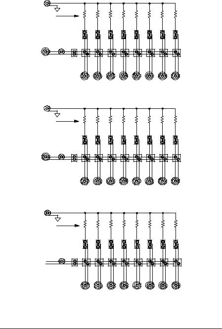
The E5255A block diagram is shown in Figure 1-5.
BIAS Input |
The BIAS INPUT ports are used to apply ac or dc bias to DUT. |
|
BIAS INPUT ports are BNC connectors. Each BIAS INPUT |
|
port is assigned to a 2×8 multiplexer block as shown in Table |
|
1-2. And you can make internal connections to connect a BIAS |
|
INPUT port to multiple blocks. Refer to Chapter 2. |
IV Input |
IV input is used for measuring/forcing dc current/voltage. You |
|
can connect the IV input to desired SMU INPUT connector |
|
(SMU1 to SMU6) of the E5250A by making an internal |
|
connection. Refer to Chapter 2. The E5250A AUX INPUT |
|
connectors are not used with the E5255A. |
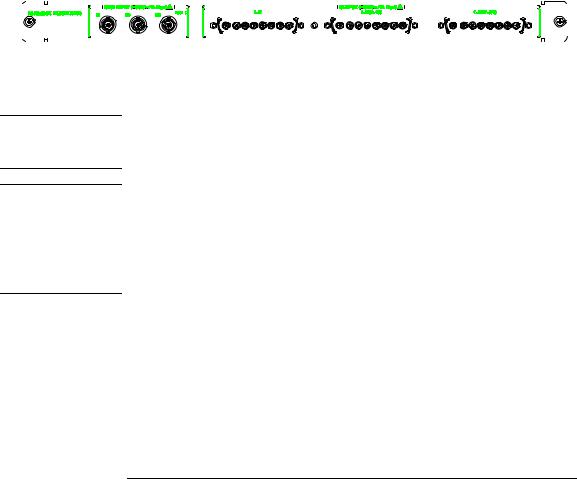
OUTPUT |
|
Connectors |
The E5255A has three 8-channel coaxial output connectors as |
|
shown in Figure 1-6. Each output connector is assigned to a 2×8 |
|
multiplexer as shown in Table 1-2. |
1-8 |
Agilent E5250A User’s Guide, Edition 9 |

|
|
Introduction |
|
|
Agilent E5255A Product Description |
|
Resistors |
Resistors connected between BIAS path and IV path are for |
|
|
protecting DUT from electrical damage. When shipped from |
|
|
factory, 0 Ω resistance is used in the E5255A. You can easily |
|
|
replace with desired resistors. Refer to Chapter 2. The |
|
|
following resistors are furnished with the E5255A: |
|
|
• 0 Ω resistors (3 sets with 10 resistors in each set) |
|
|
• 1.2 kΩ resistors (3 sets with 10 resistors in each set) |
|
|
• 22 kΩ resistors (3 sets with 10 resistors in each set) |
|
|
If you replace initial 0 Ω resistors with other resistors, you must |
|
|
cut the initial resistors. Then, if you need 0 Ω resistors again, |
|
|
use the ones listed above. |
|
Be careful about the following when selecting protective resistors: |
|
WARNING |
||
|
• If only one E5255A is installed in the mainframe, total power consumption |
|
|
by resistors must be less than 16W. |
|
• If multiple E5255As are installed in the mainframe, total power consumption by resistors must be less than 32W.
• Consider the current flows to resistor when DUT shorts, and make sure the power consumption by resistor will be within specification of resistor.
Do not use resistors that have specifications inadequate for your applications, which will result in resistors heating up, burning, or smoking.
Be careful about the heating of the rear panel of mainframe or plug-in card, which may be heated by resistors, even if you follow this warning.
Agilent E5250A User’s Guide, Edition 9 |
1-9 |
Introduction
Agilent E5255A Product Description
Figure 1-5 |
E5255A Block Diagram |
B IA S Input 1 |
|
B LO C K 1 |
|
|
|
|
|
|
|
|
|
|
|
|
|
R esis tor |
|
|
|
|
|
|
|
IV Input 1 |
|
|
|
|
|
|
|
O utput |
|
|
|
|
|
|
|
1 |
2 |
3 |
4 |
5 |
6 |
7 |
8 |
|
|
B LO C K 2 |
|
|
|
|
|
B IAS Input 2
R esis tor
IV Input 2 |
|
|
|
|
|
|
|
O utput |
|
|
|
|
|
|
|
9 |
10 |
11 |
12 |
13 |
14 |
15 |
16 |
|
|
BLO C K 3 |
|
|
|
|
|
BIA S Input 3
R esistor
IV Input 3 
O utpu t
17 |
18 |
19 |
20 |
21 |
22 |
23 |
24 |
1-10 |
Agilent E5250A User’s Guide, Edition 9 |
Introduction
Agilent E5255A Product Description
Table 1-2 |
|
E5255A Input/Output Connectors |
|
|
|
|
|
|
|
|
|
|
|
|
|
|
|
|||||||||||||||||||
|
|
|
|
|
|
|
|
|
|
|
|
|
|
|
|
|
|
|
|
|
|
|
|
|
|
|
|
|
|
|
|
|
|
|
|
|
|
|
|
|
|
|
|
2×8 multiplexer |
BIAS INPUT |
|
|
|
|
|
|
|
|
|
OUTPUT |
||||||||||||||||||
|
|
|
|
|
|
|
Output Port No. |
|
Connector |
|||||||||||||||||||||||||||
|
|
|
|
|
|
|
|
Block No. |
(Port No.) |
|
||||||||||||||||||||||||||
|
|
|
|
|
|
|
|
|
|
|
|
|
|
|
|
|
(Location) |
|||||||||||||||||||
|
|
|
|
|
|
|
|
|
|
|
|
|
|
|
|
|
|
|
|
|
|
|
|
|
|
|
|
|
|
|
||||||
|
|
|
|
|
|
|
|
|
|
|
|
|
|
|
|
|
|
|
|
|
|
|
|
|
|
|
|
|
|
|
|
|
|
|
|
|
|
|
|
|
|
|
|
|
|
|
Block1 |
BIAS1 (51) |
Output 1 to 8 |
|
Left |
||||||||||||||||||||||
|
|
|
|
|
|
|
|
|
|
|
|
|
|
|
|
|
|
|
|
|
|
|
|
|
|
|
|
|
|
|
|
|
|
|
|
|
|
|
|
|
|
|
|
|
|
|
Block2 |
BIAS2 (52) |
Output 9 to 16 |
|
Center |
||||||||||||||||||||||
|
|
|
|
|
|
|
|
|
|
|
|
|
|
|
|
|
|
|
|
|
|
|
|
|
|
|
|
|
|
|
|
|
|
|
|
|
|
|
|
|
|
|
|
|
|
|
Block3 |
BIAS3 (53) |
Output 17 to 24 |
|
Right |
||||||||||||||||||||||
|
|
|
|
|
|
|
|
|
|
|
|
|
|
|
|
|
|
|
|
|
|
|
|
|
|
|
|
|
|
|
|
|
|
|
|
|
Figure 1-6 |
|
E5255A BIAS INPUT Connectors and OUTPUT Connectors |
|
|
|
|
|
|
||||||||||||||||||||||||||||
|
|
|
|
|
|
|
|
|
|
|
|
|
|
|
|
|
|
|
|
|
|
|
|
|
|
|
|
|
|
|
|
|
|
|
|
|
|
|
|
|
|
|
|
|
|
|
|
|
|
|
|
|
|
|
|
|
|
|
|
|
|
|
|
|
|
|
|
|
|
|
|
|
|
|
|
|
|
|
|
|
|
|
|
|
|
|
|
|
|
|
|
|
|
|
|
|
|
|
|
|
|
|
|
|
|
|
|
|
|
|
|
|
|
|
|
|
|
|
|
|
|
|
|
|
|
|
|
|
|
|
|
|
|
|
|
|
|
|
|
|
|
|
|
|
|
|
|
|
|
|
|
|
|
|
|
|
|
|
|
|
|
|
|
|
|
|
|
|
|
|
|
|
|
|
|
|
|
|
|
|
|
|
|
|
|
|
|
|
|
|
|
|
|
|
|
|
|
|
|
|
|
|
|
|
|
|
|
|
|
|
|
|
|
|
|
|
|
|
|
|
|
|
|
|
|
|
|
|
|
|
|
|
|
|
|
|
|
|
|
|
|
|
|
|
|
|
|
|
|
|
|
|
|
|
|
|
|
|
WARNING
CAUTION
Do not touch the force and guard terminals of the OUTPUT connectors while the E5250A is turned on. Dangerous voltages up to the maximum input voltage may be present at the OUTPUT connectors.
The maximum voltage that can be applied to any input terminal is ±200 Vdc. The maximum current is 1 Adc at ±200 Vdc. The maximum voltage that can be applied between input terminals is 300 Vdc. Do not apply an input signal over these limits to the E5255A inputs. If you do, the E5255A will be damaged.
If you use a bias source that has current limit capability, set the bias source current limit to less than 1 Adc.
Agilent E5250A User’s Guide, Edition 9 |
1-11 |

Introduction
Options and Accessories
Options and Accessories
This section lists the options and accessories available for the E5250A.
Table 1-3 lists the options available for the E5250A.
Table 1-3 |
Options |
|
|
|
|
|
|
|
Model |
Option Item |
Description |
|
Number |
||
|
|
|
|
|
|
|
|
|
E5250A |
|
Low Leakage Switch Mainframe |
|
|
|
|
|
|
E5250A-301 |
Relay Test Adapter |
|
|
|
|
|
|
E5250A-A6J |
ANSI Z540 compliant calibration |
|
|
|
|
|
|
E5250A-UK6 |
Commercial cal. certificate w/ test data |
|
|
|
|
1-12 |
Agilent E5250A User’s Guide, Edition 9 |

Introduction
Options and Accessories
|
Table 1-4 lists accessories furnished with the E5250A, E5252A, and E5255A. |
||||
Table 1-4 |
Furnished Accessories |
|
|
||
|
|
|
|
|
|
|
Model |
Part Number |
Description |
Qty. |
|
|
Number |
||||
|
|
|
|
||
|
|
|
|
|
|
|
E5250A |
E5250-90000 |
Agilent E5250A User's Guide |
1 |
|
|
|
|
|
|
|
|
|
|
E5250-17001 |
E5250A VXI Plug&Play Driver Disk a |
1 |
|
|
|
E5250-17003 |
Agilent E5250A Program Disk. See next |
1 |
|
|
|
|
page. (LIF formatted, 3.5in diskette) |
|
|
|
|
|
|
|
|
|
|
04155-60007 |
Module Extractor |
1 |
|
|
|
|
|
|
|
|
|
8710-2151 |
Wrench (for removing plug-in card) |
1 |
|
|
|
|
|
|
|
|
|
− |
Power Cable |
1 |
|
|
|
|
|
|
|
E5252A |
E5252-90000 |
Agilent E5252A Installation Guide |
1 |
|
|
|
|
|
|
|
|
|
|
8710-2151 |
Wrench (for removing plug-in card) |
1 |
|
|
|
|
|
|
|
E5255A |
E5255-90000 |
Agilent E5255A Installation Guide |
1 |
|
|
|
|
|
|
|
|
|
|
1250-0929 |
BNC Short Cap |
3 |
|
|
|
|
|
|
|
|
|
E5255-65000 |
BIAS Input Modification Kit |
1 |
|
|
|
|
(BNC Open Cap × 2, wire × 2) |
|
|
|
|
|
|
|
|
|
|
E5255-65001 |
0 Ω Resistor Set (10 resistors) |
3 |
|
|
|
|
|
|
|
|
|
E5255-65002 |
1.2 kΩ Resistor Set (10 resistors) |
3 |
|
|
|
|
|
|
|
|
|
E5255-65003 |
22 kΩ Resistor Set (10 resistors) |
3 |
|
|
|
|
|
|
|
|
|
8710-2151 |
Wrench (for removing plug-in card) |
1 |
|
|
|
|
|
|
a.The Agilent E5250A VXIplug&play driver supports Windows XP Professional, Windows 2000, Windows NT 4.0, Windows 98, and Windows 95.
Agilent E5250A User’s Guide, Edition 9 |
1-13 |

Introduction
Options and Accessories
Contents of the E5250A Program Disk:
Virtual Front
Panel Utility Interactive control program for the E5250A. Runs on Agilent 4155/4156's built-in IBASIC controller. Refer to Chapter 5.
VFP Data Upload
Library Subprogram library used for uploading the E5250A control data (made by Virtual Front Panel Utility) to your program. Runs on HP BASIC. Refer to Chapter 6.
Capacitance
Compensation
Routine Subprogram to compensate for capacitance error caused by the E5250A and E5252A. Runs on HP BASIC. This subprogram is used to compensate the capacitance data measured by Agilent 4284A Precision LCR Meter. Refer to Chapter 6.
Sample Programs Three sample programs: one for Vth and C measurement using the E5252A, and two for HCI test and analysis using the E5255A. Runs on HP BASIC. Refer to Chapter 9.
Self-test Utility Self-test and relay test program for the E5250A. Runs on the 4155/4156's built-in IBASIC controller. Refer to Chapter 3.
1-14 |
Agilent E5250A User’s Guide, Edition 9 |
Loading...