


 Loading...
User, Programming and Service Guide
Agilent 11896A
Polarization Controller

Notice |
The information contained in this document is subject to change without |
|
notice. |
|
Agilent Technologies makes no warranty of any kind with regard to |
|
this material, including, but not limited to, the implied warranties of |
|
merchantability and tness for a particular purpose. Agilent Technologies |
|
shall not be liable for errors contained herein or for incidental or |
|
consequential damages in connection with the furnishing, performance, or use |
|
of this material. |
|
Agilent Part Number: 11896-90011 |
|
Printed in USA April 2000 |
c Copyright Agilent Technologies 2000
All Rights Reserved. Reproduction, adaptation, or translation without prior written permission is prohibited, except as allowed under the copyright laws. 1400 Fountaingrove Parkway, Santa Rosa, CA 95403-1799, USA

Certi cation
Agilent Technologies certi es that this product met its published speci cations at the time of shipment from the factory. Agilent Technologies further certi es that its calibration measurements are traceable to the United States National Institute of Standards and Technology, to the extent allowed by
the Institute's calibration facility, and to the calibration facilities of other International Standards Organization members.
iii

Warranty
This Agilent Technologies instrument product is warranted against defects in material and workmanship for a period of one year from date of shipment. During the warranty period, Agilent Technologies will, at its option, either repair or replace products which prove to be defective.
For warranty service or repair, this product must be returned to a service facility designated by Agilent Technologies. Buyer shall prepay shipping charges to Agilent Technologies and Agilent Technologies shall pay shipping charges to return the product to Buyer. However, Buyer shall pay all shipping charges, duties, and taxes for products returned to Agilent Technologies from another country.
Agilent Technologies warrants that its software and rmware designated by Agilent Technologies for use with an instrument will execute its programming instructions when properly installed on that instrument. Agilent Technologies does not warrant that the operation of the instrument, or software, orrmware will be uninterrupted or error-free.
Limitation of Warranty
The foregoing warranty shall not apply to defects resulting from improper or inadequate maintenance by Buyer, Buyer-supplied software or interfacing, unauthorized modi cation or misuse, operation outside of the environmental speci cations for the product, or improper site preparation or maintenance.
NO OTHER WARRANTY IS EXPRESSED OR IMPLIED. AGILENT TECHNOLOGIES SPECIFICALLY DISCLAIMS THE IMPLIED WARRANTIES OF MERCHANTABILITY AND FITNESS FOR A PARTICULAR PURPOSE.
Exclusive Remedies
THE REMEDIES PROVIDED HEREIN ARE BUYER'S SOLE AND EXCLUSIVE REMEDIES. AGILENT TECHNOLOGIES SHALL NOT BE LIABLE FOR
ANY DIRECT, INDIRECT, SPECIAL, INCIDENTAL, OR CONSEQUENTIAL DAMAGES, WHETHER BASED ON CONTRACT, TORT, OR ANY OTHER LEGAL THEORY.
iv

Assistance
Product maintenance agreements and other customer assistance agreements are available for Agilent Technologies products.
For any assistance, contact your nearest Agilent Technologies Service O ce.
v

C A U T I O N
W A R N I N G
Safety Symbols
The following safety symbols are used throughout this manual. Familiarize yourself with each of the symbols and its meaning before operating this instrument.
The caution sign denotes a hazard to the instrument. It calls attention to a procedure which, if not correctly performed or adhered to, could result in damage to or destruction of the instrument. Do not proceed beyond a caution sign until the indicated conditions are fully understood and met.
The warning sign denotes a life-threatening hazard. It calls attention to a procedure which, if not correctly performed or adhered to, could result in injury or loss of life. Do not proceed beyond a warning sign until the indicated conditions are fully understood and met.
Instruction The instruction manual symbol. The product is marked with this symbol when it is necessary
Manual for the user to refer to the instructions in the manual.
L
vi

W A R N I N G
W A R N I N G
W A R N I N G
W A R N I N G
General Safety Considerations
Before this instrument is switched on, make sure it has been properly
grounded through the protective conductor of the ac power cable to a socket outlet provided with protective earth contact.
Any interruption of the protective (grounding) conductor, inside or outside the instrument, or disconnection of the protective earth terminal can result in personal injury.
This is a Safety Class I product (provided with a protective earthing ground incorporated in the power cord). The mains plug shall only be inserted in a socket outlet provided with a protective earth contact. Any interruption of the protective conductor inside or outside of the instrument is likely to make the instrument dangerous. Intentional interruption is prohibited.
There are many points in the instrument which can, if contacted, cause personal injury. Be extremely careful.
Any adjustments or service procedures that require operation of the instrument with protective covers removed should be performed only by trained service personnel.
If this instrument is not used as speci ed, the protection provided by the equipment could be impaired. This instrument must be used in a normal condition (in which all means for protection are intact) only.
N O T E
Clean the cabinet using a damp cloth only.
vii

How to Use This Manual
This manual provides information about the Agilent 11896A polarization controller.
Chapter 1 |
provides general information and speci cations for the |
|
controller |
Chapter 2 |
describes how to prepare the polarization controller for |
|
use and how to make ber optic connections |
Chapter 3 |
shows how to manually control the lightwave polarization |
|
controller |
Chapter 4 |
shows how to control the lightwave polarization controller |
|
using a computer |
Chapter 5 |
provides procedures for verifying and servicing the |
|
Agilent 11896A polarization controller |
Appendix A |
selecting scan rate and measurement time |
Appendix B |
measurement considerations |
Appendix C |
provides a sample GPIB program |
viii

Contents
1. General Information |
|
Description . . . . . . . . . . . . . . . . . . . . . |
1-3 |
Instrument con guration . . . . . . . . . . . . . . |
1-4 |
Options . . . . . . . . . . . . . . . . . . . . |
1-4 |
Accessories . . . . . . . . . . . . . . . . . . . |
1-4 |
Polarization-dep endent loss measurements . . . . . . |
1-5 |
Power meter PDL measurement system . . . . . . |
1-5 |
Swept-wavelength PDL measurement system . . . . |
1-6 |
Max/min PDL measurement system . . . . . . . . |
1-8 |
Theory of Operation . . . . . . . . . . . . . . . . . |
1-10 |
Speci cations and Characteristics . . . . . . . . . . . |
1-11 |
Serial Numbers . . . . . . . . . . . . . . . . . . . |
1-14 |
Electrostatic Discharge Information . . . . . . . . . . |
1-15 |
Reducing ESD damage . . . . . . . . . . . . . . . |
1-17 |
2.Installation and Preparation for Use
Preparing the Polarization Controller for Use . . . . . . |
2-3 |
|
Initial inspection . . . . . . . . . . . . . . . . . |
2-3 |
|
Connecting the Agilent 11896A to a power source . . . |
2-4 |
|
Power requirements . . . . . . . . . . . . . . . . |
2-4 |
|
Checking the fuse . . . . . . . . . . . . . . . . . |
2-4 |
|
Power cable . . . . . . . . . . . . . . . . . . . . |
2-5 |
|
Turning on the Agilent 11896A . . . . . . . . . . . . |
2-8 |
|
Lightwave Connector Care . . . . . . . . . . . . . . |
2-9 |
|
Introduction . . . . . . . . . . . . . . . . . . . |
2-9 |
|
Cleaning and handling . . . . . . . . . . . . . . . |
2-11 |
|
De nition of terms . . . . . . . . . . . . . . . |
2-11 |
|
Handling . . . . . . . . . . . . . . . . . . . . |
2-11 |
|
Cleaning . . . . . . . . . . . . . . . . . . . . |
2-11 |
|
Cleaning non-lensed light wave connectors . . . . . . . |
2-12 |
|
Equipment . . . . . . . . . . . . . . . . . . . |
2-12 |
|
Process . . . . . . . . . . . . . . . . . . . . |
2-12 |
|
Cleaning lightwave adapters . . . . . . . . . . . . |
2-13 |
|
Equipment . . . . . . . . . . . . . . . . . . . |
2-13 |
|
Process . . . . . . . . . . . . . . . . . . . . |
2-13 |
|
Cleaning lensed connections |
. . . . . . . . . . . . |
2-13 |
Contents-1

Storage . . . . . . . . . . . . . . . . . . . . . |
2-14 |
Making connections . . . . . . . . . . . . . . . . . . |
2-15 |
Summary . . . . . . . . . . . . . . . . . . . . . |
2-16 |
Inspection . . . . . . . . . . . . . . . . . . . . |
2-16 |
Visual inspection . . . . . . . . . . . . . . . . |
2-16 |
Optical performance testing . . . . . . . . . . . . |
2-17 |
Introduction . . . . . . . . . . . . . . . . . . |
2-17 |
Insertion loss . . . . . . . . . . . . . . . . . . |
2-17 |
Return loss . . . . . . . . . . . . . . . . . . . |
2-18 |
3.Using the Agilent 11896A Polarization Controller
Front-Panel Features . . . . . . . . . . . . . . . . . |
3-3 |
Error codes . . . . . . . . . . . . . . . . . . . |
3-5 |
Rear-Panel Features . . . . . . . . . . . . . . . . . |
3-6 |
Using the Agilent 11896A . . . . . . . . . . . . . . |
3-7 |
Power-up function . . . . . . . . . . . . . . . . . |
3-8 |
To use the Manual mode . . . . . . . . . . . . . . |
3-8 |
To continuously sweep all polarization states . . . . . |
3-9 |
To set the scan rate . . . . . . . . . . . . . . . . |
3-9 |
To save an instrument state . . . . . . . . . . . . . |
3-10 |
To recall an instrument state . . . . . . . . . . . . |
3-10 |
To use the Local function . . . . . . . . . . . . . . |
3-11 |
To display or change the GPIB address . . . . . . . . |
3-11 |
4. Programming |
|
Changing the GPIB address . . . . . . . . . . . . |
4-3 |
Talking to the Instrument . . . . . . . . . . . . . . |
4-4 |
Program Message Syntax . . . . . . . . . . . . . . . |
4-5 |
Output command . . . . . . . . . . . . . . . . . |
4-5 |
Device address . . . . . . . . . . . . . . . . . . |
4-5 |
Instructions . . . . . . . . . . . . . . . . . . . . |
4-6 |
Instruction header . . . . . . . . . . . . . . . . . |
4-6 |
White space (separator) . . . . . . . . . . . . . . |
4-6 |
Program data . . . . . . . . . . . . . . . . . . . |
4-7 |
Header types . . . . . . . . . . . . . . . . . . . |
4-7 |
Simple command header . . . . . . . . . . . . . |
4-7 |
Compound command header . . . . . . . . . . . |
4-8 |
Common command header . . . . . . . . . . . . |
4-8 |
Combining commands . . . . . . . . . . . . . . . |
4-8 |
Duplicate mnemonics . . . . . . . . . . . . . . . |
4-9 |
Query command . . . . . . . . . . . . . . . . . |
4-10 |
Contents-2
Program header options . . . . . . . . . . . . . . |
4-11 |
Program data syntax rules . . . . . . . . . . . . . . . |
4-12 |
Numeric program data . . . . . . . . . . . . . . |
4-12 |
Program message terminator . . . . . . . . . . . . |
4-13 |
Selecting multiple subsystems . . . . . . . . . . . . |
4-13 |
Initialization . . . . . . . . . . . . . . . . . . . |
4-14 |
Programming over GPIB . . . . . . . . . . . . . . . |
4-15 |
Interface capabilities . . . . . . . . . . . . . . . . |
4-15 |
Command and data concepts . . . . . . . . . . . . |
4-15 |
Addressing . . . . . . . . . . . . . . . . . . . . |
4-16 |
Communicating over the bus (HP 9000 series 200/300 |
|
controller) . . . . . . . . . . . . . . . . . . . |
4-17 |
Interface select code (selects interface) . . . . . . . |
4-17 |
Instrument address (selects instrument) . . . . . . |
4-17 |
Lockout . . . . . . . . . . . . . . . . . . . . . |
4-18 |
Bus commands . . . . . . . . . . . . . . . . . . |
4-18 |
Device clear . . . . . . . . . . . . . . . . . . |
4-18 |
Interface clear . . . . . . . . . . . . . . . . . . |
4-18 |
Common commands . . . . . . . . . . . . . . . . |
4-19 |
*CLS (Clear Status) . . . . . . . . . . . . . . . |
4-19 |
*ESE (Event Status Enable) . . . . . . . . . . . |
4-20 |
*ESR (Event Status Register) . . . . . . . . . . . |
4-21 |
*IDN (Identi cation Number) . . . . . . . . . . . |
4-22 |
*OPC (Operation Complete) . . . . . . . . . . . |
4-22 |
*RCL (Recall) . . . . . . . . . . . . . . . . . |
4-23 |
*RST (Reset) . . . . . . . . . . . . . . . . . . |
4-23 |
*SAV (Save) . . . . . . . . . . . . . . . . . . |
4-23 |
*SRE (Service Request Enable) . . . . . . . . . . |
4-24 |
*STB (Status Byte) . . . . . . . . . . . . . . . |
4-25 |
*TST (Test) . . . . . . . . . . . . . . . . . . |
4-26 |
*WAI (Wait) . . . . . . . . . . . . . . . . . . |
4-26 |
Instrument speci c commands . . . . . . . . . . . |
4-27 |
:ABORt . . . . . . . . . . . . . . . . . . . . |
4-27 |
:INITiate:IMMediate . . . . . . . . . . . . . . . |
4-27 |
:PADDle:POSition . . . . . . . . . . . . . . . . |
4-28 |
:SCAN:RATE . . . . . . . . . . . . . . . . . . |
4-29 |
:SCAN:TIMer . . . . . . . . . . . . . . . . . . |
4-29 |
:SCAN:TIMer:CLEar . . . . . . . . . . . . . . |
4-30 |
:STATus:OPERation :CONDition . . . . . . . . . |
4-30 |
:STATus:OPERation :ENABle . . . . . . . . . . |
4-30 |
:STATus:OPERation :EVENt . . . . . . . . . . . |
4-31 |
Contents-3

:STATus:PRESet . . . . . . . . . . . . . . . . |
4-31 |
:STATus:QUEStionable :CONDition . . . . . . . . . . |
4-31 |
:STATus:QUEStionable :ENABle . . . . . . . . . |
4-32 |
:STATus:QUEStionable :EVENt . . . . . . . . . . |
4-32 |
:SYSTem:ERRor . . . . . . . . . . . . . . . . |
4-33 |
:SYSTem:VERSion . . . . . . . . . . . . . . . |
4-34 |
5.Veri cation and Service Information
Performing a Veri cation Check . . . . . . . . . . . . |
5-3 |
||
Verify startup . . . . . . . . . . . . . . . . . . |
5-3 |
||
Verify the SCAN RATE function . . . . . . . . . |
5-3 |
||
Verify the LOCAL function . . . . . . . . . . . . |
5-4 |
||
Verify the SAVE and RECALL functions . . . . . . |
5-4 |
||
Verify the event timer . . . . . . . . . . . . . . |
5-5 |
||
If the veri cation check fails . . . . . . . . . . . . |
5-6 |
||
Verifying the Agilent 11896A Speci cations . . . . . . . |
5-7 |
||
Insertion loss . . . . . . . . . . . . . . . . . . |
5-7 |
||
Return loss . . . . . . . . . . . . . . . . . . . |
5-8 |
||
How to Return the Agilent 11896A for Service . . . . . |
5-9 |
||
Packaging . . . . . . . . . . . . . . . . . . . . |
5-9 |
||
Instrument shipping preparation procedure . . . . . . |
5-10 |
||
Sales and service |
o ces . . . . . . . . . . . . . . |
5-12 |
|
Sales and service |
o ces . . . . . . . . . . . . . . |
5-12 |
|
Service Information . . . . . . . . . . . . . . . . . |
5-14 |
||
General information . . . . . . . . . . . . . . . . |
5-14 |
||
Serial-number information . . . . . . . . . . . . |
5-14 |
||
Safety considerations . . . . . . . . . . . . . . . |
5-14 |
||
Reliability considerations . . . . . . . . . . . . . |
5-15 |
||
Protection from electrostatic discharge . . . . . . . |
5-15 |
||
Required service tools . . . . . . . . . . . . . . |
5-16 |
||
Adjustment procedure . . . . . . . . . . . . . . . |
5-16 |
||
Replacement procedures . . . . . . . . . . . . . . |
5-17 |
||
To replace the front-panel assembly . . . . . . . . |
5-17 |
||
To replace the polarization assembly . . . . . . . . |
5-18 |
||
To replace the power supply . . . . . . . . . . . |
5-18 |
||
To replace the GPIB connector . . . . . . . . . . |
5-18 |
||
Replaceable parts . . . . . . . . . . . . . . . . . |
5-19 |
||
Replaceable parts table format . . . . . . . . . . |
5-19 |
||
Part ordering information |
. . . . . . . . . . . . . |
5-19 |
|
Direct mail-order system . . . . . . . . . . . . . |
5-20 |
||
Direct phone-order system . . . . . . . . . . . . |
5-20 |
||
Contents-4

Regular orders . . . . . . . . . . . . . . . . . |
5-20 |
Hotline orders . . . . . . . . . . . . . . . . . . . |
5-20 |
A.Choosing the Scan Rate and Measurement Time
Single wavelength PDL measurements . . . . . . . . |
A-2 |
Swept wavelength PDL measurements . . . . . . . . |
A-3 |
Depolarization application . . . . . . . . . . . . . |
A-4 |
B. Measurement Considerations |
|
Overall insertion loss . . . . . . . . . . . . . . . . |
B-2 |
Insertion loss variation with paddle position . . . . . |
B-3 |
Optical return loss . . . . . . . . . . . . . . . . . |
B-3 |
Extinction ratio . . . . . . . . . . . . . . . . . . |
B-4 |
Paddle angle repeatability . . . . . . . . . . . . . |
B-5 |
Settling time . . . . . . . . . . . . . . . . . . . |
B-5 |
Paddle rotation rates . . . . . . . . . . . . . . . |
B-5 |
Nominal quarter-w ave plates . . . . . . . . . . . . |
B-5 |
Index
Contents-5

Figures
1-1. |
Typical application setup using the Agilent 11896A |
|
|
polarization controller. . . . . . . . . . . . . . . . . |
1-3 |
1-2. |
Setup for single-wavelength PDL measurements using an |
|
|
optical power meter. . . . . . . . . . . . . . . . . . |
1-5 |
1-3. |
Setup for swept-wavelength PDL measurements using an |
|
|
optical spectrum analyzer. . . . . . . . . . . . . . . |
1-6 |
1-4. |
Example of swept-wavelength PDL test data. . . . . . . . . |
1-7 |
1-5. |
Setup for single-wavelength max/min PDL measurements. . . |
1-8 |
1-6. |
Example of max/min PDL measurement data. . . . . . . . |
1-9 |
1-7. |
Agilent 11896A polarization controller block diagram. . . . . |
1-10 |
1-8. |
Example of a static-safe work station. . . . . . . . . . . . |
1-16 |
2-1. |
Checking the fuse. . . . . . . . . . . . . . . . . . . . . |
2-5 |
5-1. |
Agilent 11896A assembly level replaceable parts. . . . . . . |
5-21 |
B-1. |
Block diagram for testing the extinction ratio of the Agilent |
|
|
11896A. . . . . . . . . . . . . . . . . . . . . . . . |
B-4 |
Contents-6

Tables
1-1. |
Performance Speci cations . . . . . . . . . . . . . . . . |
1-12 |
1-2. |
Static-Safe Accessories . . . . . . . . . . . . . . . . . . |
1-17 |
2-1. |
Accessories Supplied with the Agilent 11896A . . . . . . . |
2-3 |
2-2. |
Agilent 11896A Power Requirements . . . . . . . . . . . |
2-4 |
2-3. |
AC Power Cables Available . . . . . . . . . . . . . . . . |
2-7 |
4-1. |
Standard Event Status Enable Register . . . . . . . . . . . |
4-20 |
4-2. |
Standard Event Status Register . . . . . . . . . . . . . . |
4-21 |
4-3. |
Service Request Enable Register . . . . . . . . . . . . . |
4-24 |
4-4. |
Status Byte Register . . . . . . . . . . . . . . . . . . . |
4-25 |
4-5. |
Error Messages . . . . . . . . . . . . . . . . . . . . . |
4-33 |
5-1. |
Agilent Technologies Service Numbers . . . . . . . . . . . |
5-13 |
5-2. |
Required Tools . . . . . . . . . . . . . . . . . . . . . |
5-16 |
5-3. |
Assembly-Level Replaceable Parts . . . . . . . . . . . . . |
5-21 |
A-1. |
Selecting Averaging Time, Scan Rate and Measurement Time . |
A-3 |
Contents-7

Contents

1
General Information

General Information
What you'll nd in this chapter
A description of the Agilent 11896A polarization controller.
A list of options and accessories available.
Agilent 11896A polarization controller speci cations and characteristics.
Information about the controller's serial number label.
Information about avoiding damage to the controller from electrostatic discharge.
1-2
Description
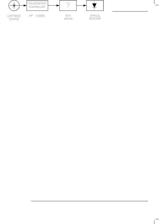
The Agilent 11896A polarization controller provides manual and automatic polarization state adjustments over a wide wavelength range (1250 to 1600 nm). All possible states of polarization are achieved with extremely small optical insertion-loss variations (60.002 dB). This performance combination maximizes measurement accuracy for power sensitive measurements such as polarization-dependent loss, gain and optical/electrical responsitivity because the measurement uncertainty
contributed by the polarization controller is minimized. A typical application con guration using the polarization controller is shown in Figure 1-1.
Figure 1-1. Typical application setup using the Agilent 11896A polarization controller.
1-3

General Information
Description
Instrument con guration
|
The standard Agilent 11896A polarization controller includes: |
||
|
|
FC/PC front-panel connector interfaces |
|
|
|
Agilent 11896A User, Programming, and Service Guide |
|
Options |
The following options are available: |
||
|
Option |
Description |
|
|
Option 010 |
Deletes FC/PC front-panel connector interfaces. |
|
|
Option 025 |
One meter pigtail ber with FC/PC connector interfaces. |
|
Accessories |
The Fiber Optics Handbook (Agilent part number 5952-9654) is an |
||
|
introduction to, and a reference for, ber-optic measurements. |
||
1-4
General Information
Description
Polarization-dependent loss measurements
Polarization-dependent loss (PDL) measurement systems can be created by combining the Agilent 11896A with instruments like the Agilent 8153A lightwave multimeter, the Agilent 71450A or Agilent 71451A optical spectrum analyzer and the Agilent 8509A/B lightwave polarization analyzer.
Power meter PDL Figure 1-2 shows how to con gure the Agilent 11896A polarization controller measurement system and the Agilent 8153A optical power meter for performing automatic
single-wavelength PDL measurements. Measurement repeatability of a few thousandths of a dB can typically be achieved.
Figure 1-2. Setup for single-wavelength PDL measurements using an optical power meter.
1-5

General Information
Description
Swept-wavelength PDL Figure 1-3 shows how to con gure the Agilent 11896A polarization controller measurement system and the Agilent 71451A optical spectrum analyzer for performing automatic
swept-wavelength PDL measurements.
Figure SWPTWAVE here.
Figure 1-3. Setup for swept-wavelength PDL measurements using an optical spectrum analyzer.
1-6
General Information
Description
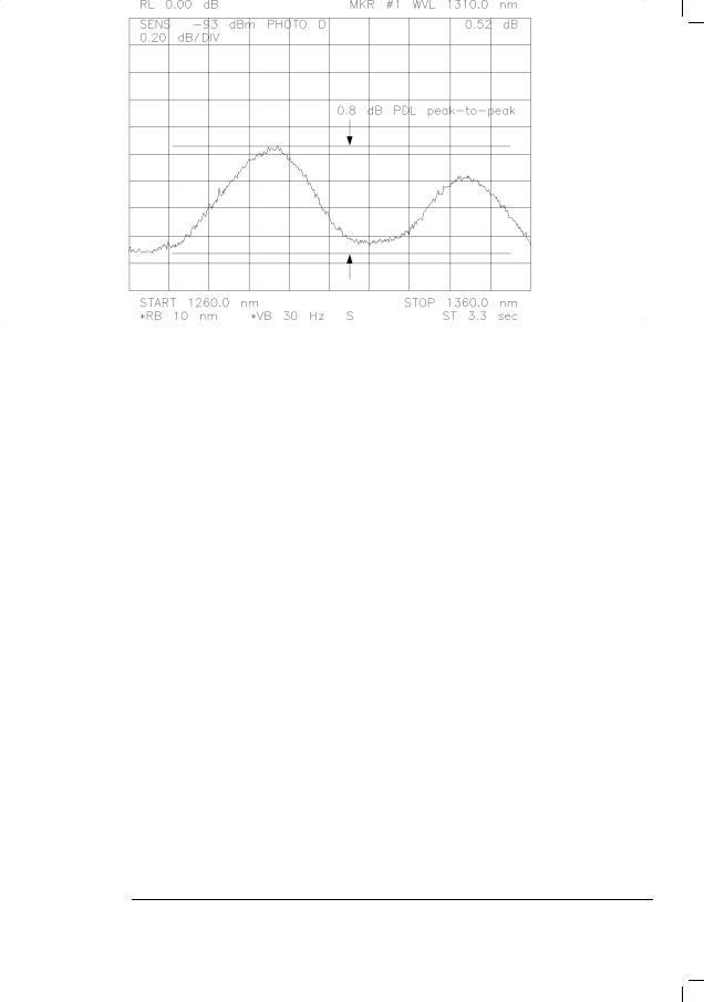
An example of swept-wavelength PDL test data, showing the amount of PDL simultaneously observed over a broad wavelength spectrum, is shown in Figure 1-4.
Figure 1-4. Example of swept-wavelength PDL test data.
1-7
General Information
Description
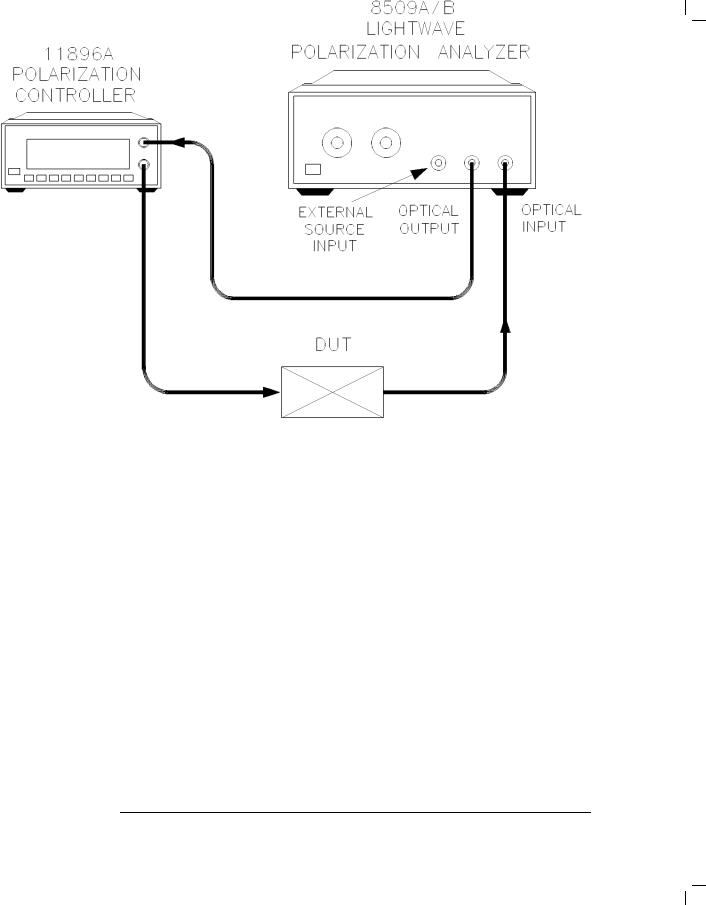
Max/min PDL |
Figure 1-5 shows how to setup the Agilent 11896A polarization controller and |
measurement system |
the Agilent 8509A/B lightwave polarization analyzer for performing automatic |
|
single-wavelength max/min PDL measurements. |
Figure 1-5. Setup for single-wavelength max/min PDL measurements.
1-8

General Information
Description
An example of max/min PDL measurement data is shown in Figure 1-6. The states of polarization are displayed as Stokes parameters and PDL markers on the Poincare sphere at the points where maximum and minimum power values actually occur during the measurement.
Figure 1-6. Example of max/min PDL measurement data.
1-9
Theory of Operation
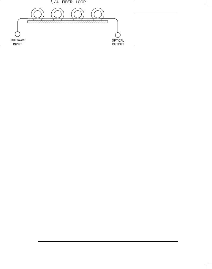
Figure 1-7. Agilent 11896A polarization controller block diagram.
The transmitted signal enters the polarization controller and passes through the internal four- ber-loop assembly. The dimensions of each loop are optimized to approximate a quarter-wave retarder response over the polarization controller's speci ed wavelength range. Complete and continuous polarization adjustability is achieved by independently adjusting each loop over an angular range of 180 . This range is divided into 1000 equal steps (000{999), providing an adjustment resolution of 0.18 . Adjustments can be made manually, using the front-panel knobs, or automatically, using remote GPIB commands or the built-in autoscanning control and the SAVE and RECALL registers.
1-10

Speci cations and Characteristics
|
This section contains speci cations and characteristics for the |
|
Agilent 11896A polarization controller. The speci cations in this chapter |
|
apply over the temperature range 0 C to +55 C (unless otherwise noted). |
|
All speci cations apply after the instrument's temperature has been stabilized |
|
after 1 hour continuous operation and self-calibration routines have been run. |
|
Fiber pigtail interfaces are assumed for all cases, except where otherwise |
|
stated. |
Speci cations |
Speci cations describe warranted performance. |
Characteristics |
Characteristics provide useful, but nonwarranted, information about the |
|
functions and performance of the instrument. Characteristics are printed in |
|
italics. |
Calibration cycle |
Agilent Technologies warrants instrument speci cations over the |
|
recommended calibration interval. To maintain speci cations, |
|
periodic recalibrations are necessary. We recommend that the |
|
Agilent 11896A polarization controller be calibrated at an Agilent |
|
Technologies service facility every 24 months. |
1-11

General Information
Speci cations and Characteristics
Table 1-1. Performance Speci cations
|
|
|
|
|
|
|
|
|
|
Standard (FC/PC |
|
Option 025 ( ber |
||||||
|
|
|
|
Performance Speci cations |
|
|
connectors) 1 |
|
|
pigtails) |
||||||||
Operating |
wavelength range |
|
|
1250 |
to |
1600 nm |
|
1250 |
to |
1600 nm |
||||||||
Insertion loss |
|
|
|
|
|
|
|
|
|
|
|
|
|
|
|
|
||
Overall |
insertion |
loss |
|
|
|
|
<2.0 |
dB2 |
|
|
<1.5 |
dB3 |
||||||
Variation |
with |
paddle |
position |
|
|
<60.02 |
dB 2 |
|
<60.002 dB 3 |
|||||||||
Variation with wavelength (1250{1600 nm) |
|
60.3 |
dB |
|
60.3 |
dB |
||||||||||||
Variation |
with |
wavelength |
(any 100 nm |
range) |
|
60.1 |
dB |
|
60.1 |
dB |
||||||||
Optical return loss |
|
|
|
|
|
35 |
dB2 |
|
|
|
55 dB3 |
|
||||||
Polarization |
extinction ratio |
|
|
|
>40 |
dB4 |
|
|
>40 |
dB4 |
||||||||
Paddle adjustment |
|
|
|
|
|
|
|
|
|
|
|
|
|
|
||||
Paddle |
angle |
resolution |
|
|
|
|
0.18 5 |
|
|
|
0.18 5 |
|
||||||
Paddle |
angular |
repeatability |
|
|
0.18 5 |
|
|
|
0.18 5 |
|
||||||||
Settling |
time |
|
|
|
|
|
|
<1 |
sec |
|
|
|
<1 sec |
|
||||
Number |
of |
scan |
rates |
|
|
|
|
8 |
|
|
|
|
|
8 |
|
|
||
Maximum |
paddle |
rotation |
rate |
|
|
360 /sec |
|
|
|
360 /sec |
|
|||||||
Number |
of |
SAVE/RECALL |
memory registers |
|
|
|
|
|
|
|
|
|||||||
|
9 |
|
|
|
|
|
9 |
|
|
|||||||||
Maximum allowable input power |
|
|
+23 dBm |
|
|
+23 dBm |
||||||||||||
|
|
|
|
|
|
|
|
|
|
|
|
|
|
|
|
|
|
|
|
|
|
|
|
|
|
Operating |
Speci cations |
|
|
|
|
|
|
|
|
||
Operating |
temperature |
|
|
|
|
0 C to 55 C |
|
|
|
|
||||||||
Non-operating, storage temperature |
|
|
040 C to +70 C |
|
|
|
|
|||||||||||
|
|
|
|
|
|
|||||||||||||
Humidity |
|
|
|
|
|
|
|
|
|
15% to 95%, non-condensing |
|
|
||||||
Power requirements |
|
|
|
|
|
47 |
to |
63 |
Hz |
|
|
|
|
|||||
|
|
|
|
|
|
|
|
|
|
90 |
to 264 |
Vrms |
|
|
|
|
||
Power consumption |
|
|
|
|
|
60 VA max |
|
|
|
|
|
|||||||
|
|
|
|
|
|
|
Physical |
Speci cations |
|
|
|
|
|
|
|
|
||
|
|
|
|
|
|
|
|
|
|
|
|
|
|
|
|
|||
Weight |
|
|
|
|
|
|
|
|
|
4.5 |
kg (10 |
lb) |
|
|
|
|
||
Dimensions |
(H 2 W 2 D) |
|
|
|
10 2 21.3 2 36 cm |
|
|
|||||||||||
|
|
|
|
|
|
|
|
|
|
(3.9 |
2 8.4 |
2 14.2 |
in) |
|
|
|||
1 Also applies to Option 010 when using FC/PC connectors. |
|
|
|
|
|
|
|
|
|
|
||||||||
2 Characteristic |
, non-warranted |
performance . |
|
|
|
|
|
|
|
|
|
|
|
|||||
3 When the Agilent 11896A is spliced into the measurement system. |
|
|
|
|
|
|
|
|
||||||||||
4 Extinction ratio refers only to the polarized portion |
of the optical signal. |
|
|
|
|
|
|
|
|
|||||||||
5 Any position. |
|
|
|
|
|
|
|
|
|
|
|
|
|
|
|
|
|
|
1-12

General Information
Speci cations and Characteristics
1-13

Serial Numbers
Agilent Technologies makes frequent improvements to its products to enhance their performance, usability, or reliability, and to control costs. Agilent Technologies service personnel have access to complete records of design changes to each type of equipment, based on the equipment's serial number. Whenever you contact Agilent Technologies about your polarization controller, have the complete serial number available to ensure obtaining the most complete and accurate information possible. A serial-number label is attached to the rear of the polarization controller. It contains the serial number and the options installed in the polarization controller. The serial number has two parts: the pre x (the rst four numbers and a letter), and the su x (the lastve numbers). Whenever you refer to the serial number when using it to obtain information about your controller, be sure to use the complete number, including the full pre x and su x.
1-14
Loading...