


 Loading...
Agilent 34401A
6 ½ Digit Multimeter
User’s Guide


 Agilent Technologies

Notices
© Agilent Technologies, Inc. 1991 - 2007
No part of this manual may be reproduced in any form or by any means (including electronic storage and retrieval or translation into a foreign language) without prior agreement and written consent from Agilent Technologies, Inc. as governed by United States and international copyright laws.
Manual Part Number
34401-90004
Edition
Seventh Edition. August 2007
Printed in Malaysia
Agilent Technologies, Inc.
3501 Stevens Creek Blvd.
Santa Clara, CA 95052 USA
Microsoft® and Windows® are U.S. registered trademarks of Microsoft Corporation.
Software Revision
This guide is valid for the firmware that was installed in the instrument at the time of manufacture. However, upgrading the firmware may add or change product features. For the latest firmware and documentation, go to the product page at:
www.agilent.com/find/34401A
Warranty
The material contained in this document is provided “as is,” and is subject to being changed, without notice, in future editions. Further, to the maximum extent permitted by applicable law, Agilent disclaims all warranties, either express or implied, with regard to this manual and any information contained herein, including but not limited to the implied warranties of merchantability and fitness for a particular purpose. Agilent shall not be liable for errors or for incidental or consequential damages in connection with the furnishing, use, or performance of this document or of any information contained herein. Should Agilent and the user have a separate written agreement with warranty terms covering the material in this document that conflict with these terms, the warranty terms in the separate agreement shall control.
Technology Licenses
The hardware and/or software described in this document are furnished under a license and may be used or copied only in accordance with the terms of such license.
Restricted Rights Legend
U.S. Government Restricted Rights. Software and technical data rights granted to the federal government include only those rights customarily provided to end user customers. Agilent provides this customary commercial license in Software and technical data pursuant to FAR 12.211 (Technical Data) and 12.212 (Computer Software) and, for the Department of Defense, DFARS 252.227-7015 (Technical Data - Commercial Items) and DFARS 227.7202-3 (Rights in Commercial Computer Software or Computer Software Documentation).
Safety Notices
CAUT ION
A CAUTION notice denotes a hazard. It calls attention to an operating procedure, practice, or the like that, if not correctly performed or adhered to, could result in damage to the product or loss of important data. Do not proceed beyond a CAUTION notice until the indicated conditions are fully understood and met.
WARN IN G
A WARNING notice denotes a hazard. It calls attention to an operating procedure, practice, or the like that, if not correctly performed or adhered to, could result in personal injury or death. Do not proceed beyond a WARNING notice until the indicated conditions are fully understood and met.
ii |
34401A User’s Guide |
Safety Information
General
Do not use this product in any manner not specified by the manufacturer. The protective features of this product may be impaired if it is used in a manner not specified in the operation instructions.
Do not install substitute parts or perform any unauthorized modification to the product. Return the product to an Agilent Technologies Sales and Service Office for service and repair to ensure that safety features are maintained.
Ground the Instrument
If your product is provided with a ground- ing-type power plug, the instrument chassis and cover must be connected to an electrical ground to minimize shock hazard. The ground pin must be firmly connected to an electrical ground (safety ground) terminal at the power outlet. Any interruption of the protective (grounding) conductor or disconnection of the protective earth terminal will cause a potential shock hazard that could result in personal injury.
Cleaning
Clean the outside of the instrument with a soft, lint-free, slightly dampened cloth. Do not use detergent or chemical solvents.
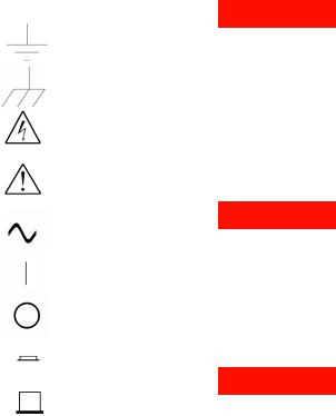
Safety Symbols
Earth Ground
Chassis Ground
Risk of electric shock
Refer to manual for additional safety information
WARN IN G
Main Power and Test Input Disconnect: Unplug instrument from wall outlet, remove power cord, and remove all probes from all terminals before servicing. Only qualified, service-trained personnel should remove the cover from the instrument.
Alternating Current
On supply
Off supply
‘In’ position of bi-stable push switch
‘Out’ position of bi-stable push switch
IEC Measurement Category II. CAT II (300V) Inputs may be connected to
mains (up to 300 VAC) under Category II overvoltage conditions.
WARN IN G
Line and Current Protection Fuses: For continued protection against fire, replace the line fuse and the current-protection fuse only with fuses of the specified type and rating.
WARN IN G
Front/Rear Switch: Do not change the position of the Front/Rear switch on the front panel while signals are present on either the front or rear set of terminals. The switch is not intended as an active multiplexer. Switching while high voltages or currents are present may cause instrument damage and lead to the risk of electric shock.
34401A User’s Guide |
iii |
WARN IN G
IEC Measurement Category II. The HI and LO input terminals may be connected to mains in IEC Category II installations for line voltages up to 300 VAC. To avoid the danger of electric shock, do not connect the inputs to mains for line voltages above 300 VAC. See "IEC Measurement Category II Overvoltage Protection" on the following page for further information.
WARN IN G
Protection Limits: To avoid instrument damage and the risk of electric shock, do not exceed any of the Protection Limits defined in the following section.
Protection Limits
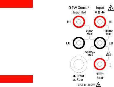
The Agilent 34401A Digital Multimeter provides protection circuitry to prevent damage to the instrument and to protect against the danger of electric shock, provided the Protection Limits are not exceeded. To ensure safe operation of the instrument, do not exceed the Protection Limits shown on the front and rear panel, and defined as follows:
Note: The front-panel terminals are shown above. The rear-panel terminals are identical. The Front/Rear switch selects the terminal set to be used. Do not operate this switch while signals are present on the front or rear terminals. The current-protec- tion fuse is on the rear panel.
Input Terminal Protection
Limits
Protection Limits are defined for the input terminals:
Main Input (HI and LO) Terminals. The HI and LO input terminals are used for voltage, resistance, frequency (period), and diode test measurements. Two Protection Limits are defined for these terminals:
HI to LO Protection Limit. The Protection Limit from HI to LO (Input terminals) is 1000 VDC or 750 VAC, which is also the maximum voltage measurement. This limit can also be expressed as 1000 Vpk maximum.
LO to Ground Protection Limit. The LO input terminal can safely "float" a maximum of 500 Vpk relative to ground.
As is implied by the above limits, the Protection Limit for the HI input terminal is a maximum of 1500 Vpk relative to ground.
Current Input Terminal. The current input ("I") terminal has a Protection Limit of 3A (rms) maximum current flowing from the LO input terminal. Note that the current input terminal will be at approximately the same voltage as the LO terminal.
Note: The current-protection circuitry includes a fuse on the rear panel. To maintain protection, replace this fuse only with a fuse of the specified type and rating.
Sense Terminal Protection
Limits
The HI and LO sense terminals are used only for four-wire resistance and temperature measurements ("Ω 4W"). The Protection Limit is 200 Vpk for all of the terminal pairings:
LO sense to LO input
HI sense to LO input
HI sense to LO sense
Note: The 200 Vpk limit on the sense terminals is the Protection Limit. Operational voltages in resistance measurements are much lower — less than 10 V in normal operation.
IEC Measurement Category II
Overvoltage Protection
To protect against the danger of electric shock, the Agilent 34401A Digital Multimeter provides overvoltage protection for line-voltage mains connections meeting both of the following conditions:
The HI and LO input terminals are connected to the mains under Measurement Category II conditions, defined below,
and
The mains are limited to a maximum line voltage of 300 VAC.
iv |
34401A User’s Guide |

IEC Measurement Category II includes electrical devices connected to mains at an outlet on a branch circuit. Such devices include most small appliances, test equipment, and other devices that plug into a branch outlet or socket. The 34401A may be used to make measurements with the HI and LO inputs connected to mains in such devices, or to the branch outlet itself (up to 300 VAC). However, the 34401A may not be used with its HI and LO inputs connected to mains in permanently installed electrical devices such as the main circuit-breaker panel, sub-panel disconnect boxes, or permanently wired motors. Such devices and circuits are subject to overvoltages that may exceed the protection limits of the 34401A.
Note: Voltages above 300 VAC may be measured only in circuits that are isolated from mains. However, transient overvoltages are also present on circuits that are isolated from mains. The Agilent 34401A are designed to safely withstand occasional transient overvoltages up to 2500 Vpk. Do not use this equipment to measure circuits where transient overvoltages could exceed this level.
Additional Notices
Waste Electrical and Electronic Equipment (WEEE) Directive 2002/96/EC
This product complies with the WEEE Directive (2002/96/EC) marking requirement. The affixed product label (see below) indicates that you must not discard this electrical/electronic product in domestic household waste.
Product Category: With reference to the equipment types in the WEEE directive Annex 1, this product is classified as a "Monitoring and Control instrumentation" product.
Do not dispose in domestic household waste.
To return unwanted products, contact your local Agilent office, or see www.agilent.com/environment/product for more information.
Agilent 34138A Test Lead Set
The Agilent 34401A is compatible with the Agilent 34138A Test Lead Set described below.
Test Lead Ratings
Test Leads - 1000V, 15A
Fine Tip Probe Attachments - 300V, 3A
Mini Grabber Attachment - 300V, 3A
SMT Grabber Attachments - 300V, 3A
Operation
The Fine Tip, Mini Grabber, and SMT Grabber attachments plug onto the probe end of the Test Leads.
Maintenance
If any portion of the Test Lead Set is worn or damaged, do not use. Replace with a new Agilent 34138A Test Lead Set.
WARN IN G
If the Test Lead Set is used in a manner not specified by Agilent Technologies, the protection provided by the Test Lead Set may be impaired. Also, do not use a damaged or worn Test Lead Set. Instrument damage or personal injury may result.
34401A User’s Guide |
v |

|
|
DECLARATION OF CONFORMITY |
|
|
|
According to ISO/IEC Guide 22 and CEN/CENELEC EN 45014 |
|
|
|
|
|
Manufacturer’s Name: |
Agilent Technologies, Incorporated |
|
|
Manufacturer’s Address: |
815 – 14th St. SW |
|
|
|
Loveland, Colorado 80537 |
|
|
|
USA |
|
|
Declares, that the product |
|
|
|
Product Name: |
Multimeter |
|
|
Model Number: |
34401A |
|
|
Product Options: |
This declaration covers all options of the above product(s). |
|
|
Conforms with the following European Directives:
The product herewith complies with the requirements of the Low Voltage Directive 73/23/EEC and the EMC Directive 89/336/EEC (including 93/68/EEC) and carries the CE Marking accordingly.
Conforms with the following product standards: |
|
|
EMC |
Standard |
Limit |
|
IEC 61326-1:1997+A1:1998 / EN 61326-1:1997+A1:1998 |
|
|
CISPR 11:1990 / EN 55011:1991 |
Group 1 Class A |
|
IEC 61000-4-2:1995+A1:1998 / EN 61000-4-2:1995 |
4kV CD, 8kV AD |
|
IEC 61000-4-3:1995 / EN 61000-4-3:1995 |
3 V/m, 80-1000 MHz |
|
IEC 61000-4-4:1995 / EN 61000-4-4:1995 |
0.5kV signal lines, 1kV power lines |
|
IEC 61000-4-5:1995 / EN 61000-4-5:1995 |
0.5 kV line-line, 1 kV line-ground |
|
IEC 61000-4-6:1996 / EN 61000-4-6:1996 |
3V, 0.15-80 MHz |
|
IEC 61000-4-11:1994 / EN 61000-4-11:1994 |
Dips: 30% 10ms; 60% 100ms |
|
Canada: ICES-001:1998 |
Interrupt > 95%@5000ms |
|
|
|
|
Australia/New Zealand: AS/NZS 2064.1 |
|
|
The product was tested in a typical configuration with Agilent Technologies test systems. |
|
Safety |
IEC 61010-1:1990+A1:1992+A2:1995 / EN 61010-1:1993+A2:1995 |
|
|
Canada: CSA C22.2 No. 1010.1:1992 |
|
|
UL 3111-1: 1994 |
|
18 July 2001 |
|
|
Date |
|
Ray Corson |
|
|
Product Regulations Program Manager |
For further information, please contact your local Agilent Technologies sales office, agent or distributor.
Authorized EU-representative: Agilent Technologies Deutschland GmbH, Herrenberger Straβe 130, D 71034 Böblingen, Germany

Note: Unless otherwise indicated, this manual applies to all Serial Numbers.
The Agilent Technologies 34401A is a 61⁄2-digit, high-performance digital multimeter. Its combination of bench-top and system features makes this multimeter a versatile solution for your measurement needs now and in the future.
Convenient Bench-Top Features
•Highly visible vacuum-fluorescent display
•Built-in math operations
•Continuity and diode test functions
•Hands-free, Reading Hold feature
•Portable, ruggedized case with non-skid feet
Flexible System Features
•GPIB (IEEE-488) interface and RS-232 interface
•Standard programming languages: SCPI, Agilent 3478A, and Fluke 8840
•Reading rates up to 1000 readings per second
•Storage for up to 512 readings
•Limit testing with pass/fail signals
•Optional 34812A BenchLink/Meter Software for Microsoft® WindowsTM
Agilent 34401A
Multimeter
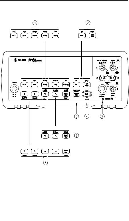
The Front Panel at a Glance
|
|
|
|
|
|
|
|
|
|
|
|
|
|
|
|
|
|
|
|
|
|
|
|
|
|
|
|
|
|
|
|
|
|
|
|
|
|
|
|
|
|
|
|
|
|
|
|
|
|
|
|
|
|
|
|
|
|
|
|
|
|
|
|
|
|
|
|
|
|
|
|
|
|
|
|
|
|
|
|
|
|
|
|
|
|
|
|
|
|
|
|
|
|
|
|
|
|
|
|
|
|
|
|
|
|
|
|
|
|
|
|
|
|
|
|
|
|
|
|
|
|
|
|
|
|
|
|
|
|
|
|
|
|
|
|
|
|
|
|
|
|
|
|
|
|
|
|
|
|
|
|
|
|
|
|
|
|
|
|
|
|
|
|
|
|
|
|
|
|
|
|
|
|
|
|
|
|
|
|
|
|
|
|
|
|
|
|
|
|
|
|
|
|
|
|
|
|
|
|
|
|
|
|
|
|
|
|
|
|
|
|
|
|
|
|
|
|
|
|
|
|
|
|
|
|
|
|
|
|
|
|
|
|
|
|
|
|
|
|
|
|
|
|
|
|
|
|
|
|
|
|
|
|
|
|
|
|
|
|
|
|
|
|
|
|
|
|
|
|
|
|
|
|
|
|
|
|
|
|
|
|
|
|
|
|
|
|
|
|
|
|
|
|
|
|
|
|
|
|
|
|
|
|
|
|
|
|
|
|
|
|
|
|
|
|
|
|
|
|
|
|
|
|
|
|
|
|
|
|
|
|
|
|
|
|
|
|
|
|
|
|
|
|
|
|
|
|
|
|
|
|
|
|
|
|
|
|
|
|
|
|
|
|
|
|
|
|
|
|
|
|
|
|
|
|
|
|
|
|
|
|
|
|
|
|
|
|
|
|
|
|
|
|
|
|
|
|
|
|
|
|
|
|
|
|
|
|
|
|
|
|
|
|
|
|
|
|
|
|
|
|
|
|
|
|
|
|
|
|
|
|
|
|
|
|
|
|
|
|
|
|
|
|
|
|
|
|
|
|
|
|
|
|
|
|
|
|
|
|
|
|
|
|
|
|
|
|
|
|
|
|
|
|
|
|
|
|
|
|
|
|
|
|
|
|
|
|
|
|
|
|
|
|
|
|
|
|
|
|
|
|
|
|
|
|
|
|
|
|
|
|
|
|
|
|
|
|
|
|
|
|
|
|
|
|
|
|
|
|
|
|
|
|
|
|
|
|
|
|
|
|
|
|
|
|
|
|
|
|
|
|
|
|
|
|
|
|
|
|
|
|
|
|
|
|
|
|
|
|
|
|
|
|
|
|
|
|
|
|
|
|
|
|
|
|
|
|
|
|
|
|
|
|
|
|
|
|
|
|
|
|
|
|
|
|
|
|
|
|
|
|
|
|
|
|
|
|
|
|
|
|
|
|
|
|
|
|
|
|
|
|
|
|
|
|
|
|
|
|
|
|
|
|
|
|
|
|
|
|
|
|
|
|
|
|
|
|
|
|
|
|
|
|
|
|
|
|
|
|
|
|
|
|
|
|
|
|
|
|
|
|
|
|
|
|
|
|
|
|
|
|
|
|
|
|
|
|
|
|
|
|
|
|
|
|
|
|
|
|
|
|
|
|
|
|
|
|
|
|
|
|
|
|
|
|
|
|
|
|
|
|
|
|
|
|
|
|
|
|
|
|
|
|
|
|
|
|
|
|
|
|
|
|
|
|
|
|
|
|
|
|
|
|
|
|
|
|
|
|
|
|
|
|
|
|
|
|
|
|
|
|
|
|
|
|
|
|
|
|
|
|
|
|
|
|
|
|
|
|
|
|
|
|
|
|
|
|
|
|
|
|
|
|
|
|
|
|
|
|
|
|
|
|
|
|
|
|
|
|
|
|
|
|
|
|
|
|
|
|
|
|
|
|
|
|
|
|
|
|
|
|
|
|
|
|
|
|
|
|
|
|
|
|
|
|
|
|
|
|
|
|
|
|
|
|
|
|
|
|
|
|
|
|
|
|
|
|
|
|
|
|
|
|
|
|
|
|
|
|
|
|
|
|
|
|
|
|
|
|
|
|
|
|
|
|
|
|
|
|
|
|
|
|
|
|
|
|
|
|
|
|
|
|
|
|
|
|
|
|
|
|
|
|
|
1 |
Measurement Function keys |
5 |
Front / Rear Input Terminal Switch |
|||||||||||||||||||||||||||||||||||||||||||||||||||||||||||
2 |
Math Operation keys |
6 |
Range / Number of Digits Displayed keys |
|||||||||||||||||||||||||||||||||||||||||||||||||||||||||||
3 |
Single Trigger / Autotrigger / Reading Hold key |
7 |
Menu Operation keys |
|||||||||||||||||||||||||||||||||||||||||||||||||||||||||||
4 |
Shift / Local key |
|
|
|
|
|
|
|
|
|
|
|
|
|
|
|
|
|
|
|
|
|
|
|
|
|
|
|
|
|
|
|
|
|
|
|
|
|
|
|
||||||||||||||||||||||
2
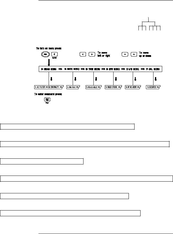
The Front-Panel Menu at a Glance
The menu is organized in a top-down tree structure with three levels.
A: MEASurement MENU
1: AC FILTER > 2: CONTINUITY > 3: INPUT R > 4: RATIO FUNC > 5: RESOLUTION
B: MATH MENU
1: MIN-MAX > 2: NULL VALUE > 3: dB REL > 4: dBm REF R > 5: LIMIT TEST > 6: HIGH LIMIT > 7: LOW LIMIT
C:TRIGger MENU
1:READ HOLD > 2: TRIG DELAY > 3: N SAMPLES
D:SYStem MENU
1: RDGS STORE > 2: SAVED RDGS > 3: ERROR > 4: TEST > 5: DISPLAY > 6: BEEP > 7: COMMA > 8: REVISION
E: Input / Output MENU
1: GPIB ADDR > 2: INTERFACE > 3: BAUD RATE > 4: PARITY > 5: LANGUAGE
F: CALibration MENU*
1: SECURED > [ 1: UNSECURED ] > [ 2: CALIBRATE ] > 3: CAL COUNT > 4: MESSAGE
*The commands enclosed in square brackets ( [ ] ) are “hidden” unless the multimeter is UNSECURED for calibration.
3
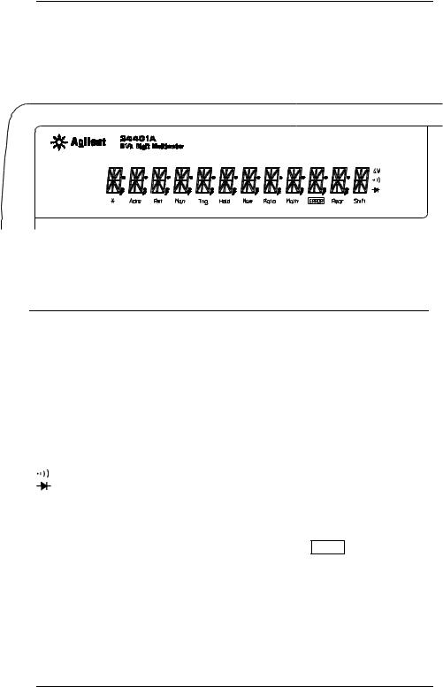
Display Annunciators
Adrs
Rmt
Man
Trig
Hold
Mem
Ratio
Math ERROR Rear Shift
Turns on during a measurement.
Multimeter is addressed to listen or talk over the GPIB interface. Multimeter is in remote mode (remote interface).
Multimeter is using manual ranging (autorange is disabled). Multimeter is waiting for a single trigger or external trigger. Reading Hold is enabled.
Turns on when reading memory is enabled. Multimeter is in dcv:dcv ratio function.
A math operation is enabled (null, min-max, dB, dBm, or limit test). Hardware or remote interface command errors are detected.
Rear input terminals are selected.
“Shift” key has been pressedPress. “Shift” again to turn off.
Multimeter is in 4-wire ohms function. Multimeter is in continuity test function. Multimeter is in diode test function.
To review the display annunciators, hold down the Shift key as you turn on the multimeter.
4
The Rear Panel at a Glance
|
|
|
|
|
|
|
|
|
|
|
|
|
|
|
|
|
|
|
|
|
|
|
|
|
|
|
|
|
|
|
|
|
|
|
|
|
|
|
|
|
|
|
|
|
|
|
|
|
|
|
|
|
|
|
|
|
|
|
|
|
|
|
|
|
|
|
|
|
|
|
|
|
|
|
|
|
|
|
|
|
|
|
|
|
|
|
|
|
|
|
|
|
|
|
|
|
|
|
|
|
|
|
|
|
|
|
|
|
|
|
|
|
|
|
|
|
|
|
|
|
|
|
|
|
|
|
|
|
|
|
|
|
|
|
|
|
|
|
|
|
|
|
|
|
|
|
|
|
|
|
|
|
|
|
|
|
|
|
|
|
|
|
|
|
|
|
|
|
|
|
|
|
|
|
|
|
|
|
|
|
|
|
|
|
|
|
|
|
|
|
|
|
|
|
|
|
|
|
|
|
|
|
|
|
|
|
|
|
|
|
|
|
|
|
|
|
|
|
|
|
|
|
|
|
|
|
|
|
|
|
|
|
|
|
|
|
|
|
|
1 |
|
Chassis Ground |
5 |
Voltmeter Complete Output Terminal |
|||||||||||||||||||||||||
2 |
|
Power-Line Fuse-Holder Assembly |
6 |
External Trigger Input Terminal |
|||||||||||||||||||||||||
3 |
|
Power-Line Voltage Setting |
7 |
GPIB (IEEE-488) Interface connector |
|||||||||||||||||||||||||
4 |
|
Front and Rear Current Input Fuse |
8 |
RS-232 interface connector |
|||||||||||||||||||||||||
Use the front-panel Input / Output Menu to:
•Select the GPIB or RS-232 interface (see chapter 4).
•Set the GPIB bus address (see chapter 4).
•Set the RS-232 baud rate and parity (see chapter 4).
5

In This Book
Quick Start Chapter 1 prepares the multimeter for use and helps you get familiar with a few of its front-panel features.
Front-Panel Menu Operation Chapter 2 introduces you to the front-panel menu and describes some of the multimeter’s menu features.
Features and Functions Chapter 3 gives a detailed description of the multimeter’s capabilities and operation. You will find this chapter useful whether you are operating the multimeter from the front panel or over the remote interface.
Remote Interface Reference Chapter 4 contains reference information to help you program the multimeter over the remote interface.
Error Messages Chapter 5 lists the error messages that may appear as you are working with the multimeter. Each listing contains enough information to help you diagnose and solve the problem.
Application Programs Chapter 6 contains several remote interface application programs to help you develop programs for your measurement application.
Measurement Tutorial Chapter 7 discusses measurement considerations and techniques to help you obtain the best accuracies and reduce sources of measurement error.
Specifications Chapter 8 lists the multimeter’s specifications and describes how to interpret these specifications.
If you have questions relating to the operation of the Agilent 34401A, call 1-800-452-4844 in the United States, or contact your nearest Agilent Sales Office.
If your 34401A fails within one year of purchase, Agilent will repair or replace it free of charge. Call 1-877-444-7278 (“Agilent Express”) in the United States, or contact your nearest Agilent Sales Office.
6

Contents
Chapter 1 Quick Start
To Prepare the Multimeter for Use 13 If the Multimeter Does Not Turn On 14 To Adjust the Carrying Handle 16
To Measure Voltage 17 To Measure Resistance 17 To Measure Current 18
To Measure Frequency (or Period) 18 To Test Continuity 19
To Check Diodes 19
To Select a Range 20 To Set the Resolution 21
Front-Panel Display Formats 22 To Rack Mount the Multimeter 23
Chapter 2 Front-Panel Menu Operation
Front-Panel Menu Reference 27
A Front-Panel Menu Tutorial 29
To Turn Off the Comma Separator 37
To Make Null (Relative) Measurements 38
To Store Minimum and Maximum Readings 39 To Make dB Measurements 40
To Make dBm Measurements 41 To Trigger the Multimeter 42 To Use Reading Hold 43
To Make dcv:dcv Ratio Measurements 44 To Use Reading Memory 46
Chapter 3 Features and Functions
Measurement Configuration
AC Signal Filter 51
Continuity Threshold Resistance 52
DC Input Resistance 53
Resolution 54
Integration Time 57
Front / Rear Input Terminal Switching 58
Autozero 59
Ranging 60
Contents
7

Contents
Contents
Chapter 3 Features and Functions (continued)
Math Operations
Min-Max Operation 64
Null (Relative) Operation 65
dB Measurements 67
dBm Measurements 68
Limit Testing 69
Triggering
Trigger Source Choices 73
The Wait-for-Trigger State 76
Halting a Measurement in Progress 76
Number of Samples 77
Number of Triggers 78
Trigger Delay 79
Automatic Trigger Delays 81
Reading Hold 82
Voltmeter Complete Terminal 83
External Trigger Terminal 83
System-Related Operations
Reading Memory 84
Error Conditions 85
Self-Test 86
Display Control 87
Beeper Control 88
Comma Separators 89
Firmware Revision Query 89
SCPI Language Version Query 90
Remote Interface Configuration
GPIB Address 91
Remote Interface Selection 92
Baud Rate Selection (RS-232) 93
Parity Selection (RS-232) 93
Programming Language Selection 94
Calibration
Calibration Security 95
Calibration Count 98
Calibration Message 99
Operator Maintenance
To Replace the Power-Line Fuse 100
To Replace the Current Input Fuses 100
Power-On and Reset State 101
8

Contents
Chapter 4 Remote Interface Reference
Command Summary 105
Simplified Programming Overview 112
The MEASure? and CONFigure Commands 117 Measurement Configuration Commands 121 Math Operation Commands 124
Triggering 127
Triggering Commands 130 System-Related Commands 132 The SCPI Status Model 134 Status Reporting Commands 144 Calibration Commands 146
RS-232 Interface Configuration 148 RS-232 Interface Commands 153
An Introduction to the SCPI Language 154 Output Data Formats 159
Using Device Clear to Halt Measurements 160 TALK ONLY for Printers 160
To Set the GPIB Address 161
To Select the Remote Interface 162 To Set the Baud Rate 163
To Set the Parity 164
To Select the Programming Language 165
Alternate Programming Language Compatibility 166 SCPI Compliance Information 168
IEEE-488 Compliance Information 169
Chapter 5 Error Messages
Execution Errors 173
Self-Test Errors 179
Calibration Errors 180
Chapter 6 Application Programs
Using MEASure? for a Single Measurement 185 Using CONFigure with a Math Operation 186 Using the Status Registers 188
RS-232 Operation Using QuickBASIC 192 RS-232 Operation Using Turbo C 193
Contents
9

Contents
Contents
Chapter 7 Measurement Tutorial
Thermal EMF Errors 199 Loading Errors (dc volts) 199 Leakage Current Errors 199
Rejecting Power-Line Noise Voltages 200 Common Mode Rejection (CMR) 201 Noise Caused by Magnetic Loops 201 Noise Caused by Ground Loops 202 Resistance Measurements 203
4-Wire Ohms Measurements 203 Removing Test Lead Resistance Errors 204 Power Dissipation Effects 204
Settling Time Effects 204
Errors in High Resistance Measurements 205 DC Current Measurement Errors 205
True RMS AC Measurements 206 Crest Factor Errors 207
Loading Errors (ac volts) 209 Measurements Below Full Scale 210 High-Voltage Self-Heating Errors 210
Temperature Coefficient and Overload Errors 210 Low-Level Measurement Errors 211
Common Mode Errors 212
AC Current Measurement Errors 212 Frequency and Period Measurement Errors 213
Making High-Speed DC and Resistance Measurements 213 Making High-Speed AC Measurements 214
Chapter 8 Specifications
DC Characteristics 216
AC Characteristics 218
Frequency and Period Characteristics 220 General Information 222
Product Dimensions 223
To Calculate Total Measurement Error 224 Interpreting Multimeter Specifications 226 Configuring for Highest Accuracy Measurements 229
Index 231
Declaration of Conformity 237
10

1
1
Quick Start
Quick Start
One of the first things you will want to do with your multimeter is to become acquainted with its front panel. We have written the exercises in this chapter to prepare the multimeter for use and help you get familiar with some of its front-panel operations.
The front panel has two rows of keys to select various functions and operations. Most keys have a shifted function printed in blue above the key. To perform a shifted function, press Shift (the Shift annunciator will turn on). Then, press the key that has the desired label above it. For example, to select the dc current function,
press Shift 
 DC V .
If you accidentally press Shift , just press it again to turn off the Shift annunciator.
The rear cover of this book is a fold-out Quick Reference Guide. On this cover you will find a quick summary of various multimeter features.
12

Chapter 1 Quick Start
To Prepare the Multimeter for Use
1
To Prepare the Multimeter for Use
The following steps help you verify that the multimeter is ready for use.
1 Check the list of supplied items.
Verify that you have received the following items with your multimeter. If anything is missing, contact your nearest Agilent Sales Office.
One test lead kit.
One power cord.
This User’s Guide.
One Service Guide.
One folded Quick Reference card.
Certificate of Calibration.
2Connect the power cord and turn on the multimeter.
The front-panel display will light up while the multimeter performs its power-on self-test. The GPIB bus address is displayed. Notice that the multimeter powers up in the dc voltage function with autoranging enabled.
To review the power-on display with all annunciators turned on, hold down Shift as you turn on the multimeter.
3Perform a complete self-test.
The complete self-test performs a more extensive series of tests than those performed at power-on. Hold down Shift as you press the Power switch to turn on the multimeter; hold down the key for more than 5 seconds. The self-test will begin when you release the key.
If the self-test is successful, “PASS” is displayed. If the self-test is
not successful, “FAIL” is displayed and the ERROR annunciator turns on. See the Service Guide for instructions on returning the multimeter to Agilent for service.
13

Chapter 1 Quick Start
If the Multimeter Does Not Turn On
1
If the Multimeter Does Not Turn On
Use the following steps to help solve problems you might encounter when turning on the multimeter. If you need more help, see the
Service Guide for instructions on returning the multimeter to Agilent for service.
1Verify that there is ac power to the multimeter.
First, verify that the multimeter’s Power switch is in the “On” position. Also, make sure that the power cord is firmly plugged into the power module on the rear panel. You should also make sure that the power source you plugged the multimeter into is energized.
2Verify the power-line voltage setting.
The line voltage is set to the proper value for your country when the multimeter is shipped from the factory. Change the voltage setting if it is not correct. The settings are: 100, 120, 220, or 240 Vac (for 230 Vac operation, use the 220 Vac setting).
See the next page if you need to change the line-voltage setting.
3Verify that the power-line fuse is good.
The multimeter is shipped from the factory with a 250 mA fuse installed. This is the correct fuse for all line voltages.
See the next page if you need to replace the power-line fuse.
To replace the 250 mAT fuse, order Agilent part number 2110-0817.
14

Chapter 1 Quick Start
If the Multimeter Does Not Turn On
1
1Remove the power cord. Remove the fuse-holder assembly from the rear panel.
2Remove the line-voltage selector from the assembly.
3Rotate the line-voltage selector until the correct voltage appears in the window.
See rear panel for proper fuse rating.
Agilent Part Number: 2110-0817 (250 mAT)
4Replace the fuse-holder assembly in the rear panel.
100, 120, 220 (230) or 240 Vac
Verify that the correct line voltage is selected and the power-line fuse is good.
15
Chapter 1 Quick Start
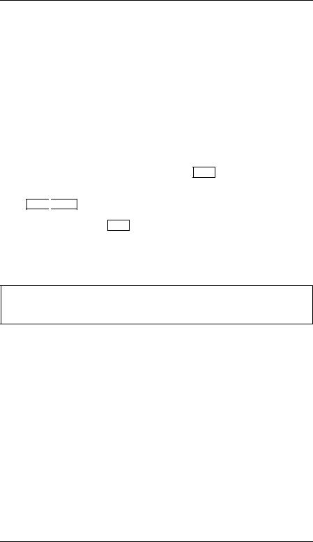
To Adjust the Carrying Handle
To Adjust the Carrying Handle
To adjust the position, grasp the handle by the sides and pull outward. Then, rotate the handle to the desired position.
Bench-top viewing positions |
Carrying position |
16
Chapter 1 Quick Start
To Measure Voltage
1
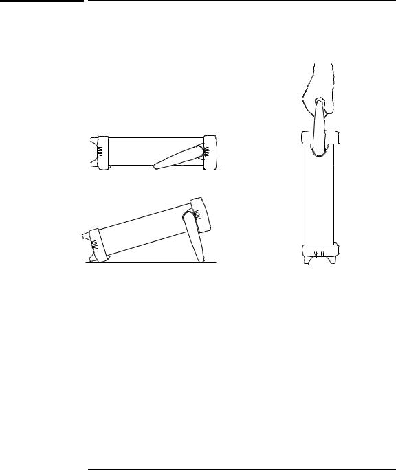
To Measure Voltage
Ranges: 100 mV, 1 V, 10 V, 100 V, 1000 V (750 Vac)
Maximum resolution: 100 nV (on 100 mV range)
AC technique: true RMS, ac-coupled
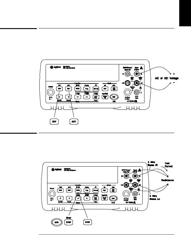
To Measure Resistance
Ranges: 100 Ω, 1 kΩ , 10 kΩ , 100 kΩ , 1 MΩ , 10 MΩ , 100 MΩ Maximum resolution: 100 µΩ (on 100 ohm range)
17
Chapter 1 Quick Start
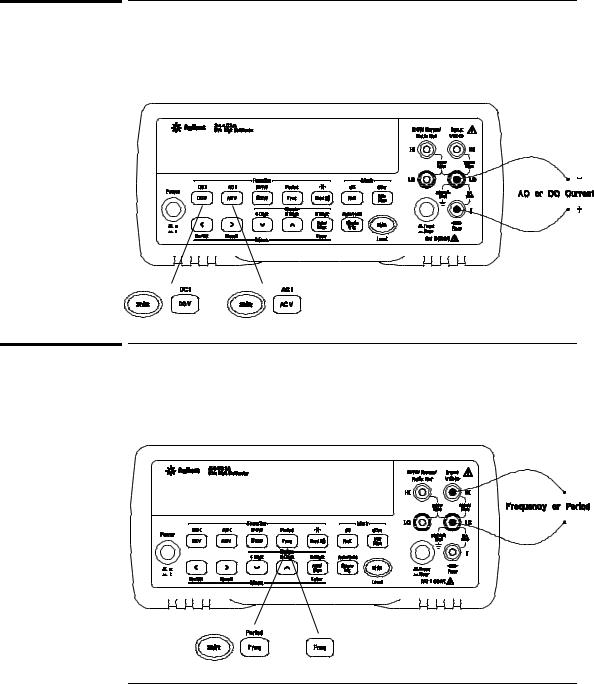
To Measure Current
To Measure Current
Ranges: 10 mA (dc only), 100 mA (dc only), 1 A , 3 A Maximum resolution: 10 nA (on 10 mA range)
AC technique: true RMS, ac-coupled
To Measure Frequency (or Period)
Measurement band: 3 Hz to 300 kHz (0.33 sec to 3.3 sec) Input signal range: 100 mVac to 750 Vac
Technique: reciprocal counting
18
Chapter 1 Quick Start
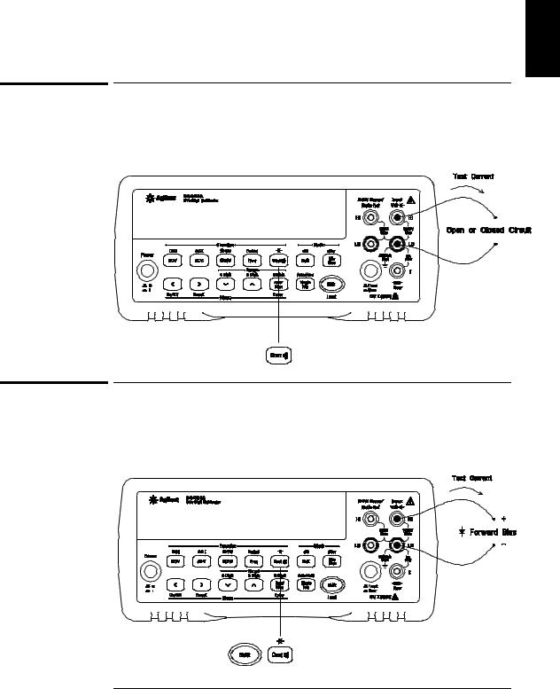
To Test Continuity
1
To Test Continuity
Test current source: 1 mA
Maximum resolution: 0.1 Ω (range is fixed at 1 kohm)
Beeper threshold: 1 Ω to 1000 Ω (beeps below adjustable threshold)
To Check Diodes
Test current source: 1 mA
Maximum resolution: 100 µV (range is fixed at 1 Vdc)
Beeper threshold: 0.3 volts ≤ Vmeasured ≤ 0.8 volts (not adjustable)
19
Chapter 1 Quick Start
To Select a Range
To Select a Range
You can let the multimeter automatically select the range using autoranging or you can select a fixed range using manual ranging.
Selects a lower range and disables autoranging.
Selects a higher range and disables autoranging.
Toggles between autoranging and manual ranging.
Man annunciator is on when manual range is enabled.
•Autoranging is selected at power-on and after a remote interface reset.
•Autorange thresholds:
Down range at <10% of range
Up range at >120% of range
•If the input signal is greater than the present range can measure, the multimeter will give an overload indication (“OVLD”).
•For frequency and period measurements from the front panel, ranging applies to the signal’s input voltage, not its frequency.
• The range is fixed for continuity (1 kΩ range) and diode (1 Vdc range).
Ranging is local to the selected function. This means that you can select the ranging method (auto or manual) for each function independently. When manually ranging, the selected range is local to the function;
the multimeter remembers the range when you switch between functions.
20

Chapter 1 Quick Start
To Set the Resolution
1
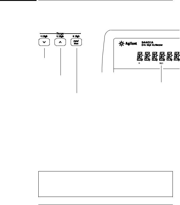
To Set the Resolution
You can set the display resolution to 41⁄2, 51⁄2, or 61⁄2 digits either to optimize measurement speed or noise rejection. In this book, the most significant digit (leftmost on the display) is referred to as the “1⁄2” digit, since it can only be a “0” or “1.”
Press the Shift key.
Selects 41⁄2 digits.
Selects 51⁄2 digits.
Selects 61⁄2 digits (most noise rejection).
•The resolution is set to 51⁄2 digits at power-on and after a remote interface reset.
•The resolution is fixed at 51⁄2 digits for continuity and diode tests.
•You can also vary the number of digits displayed using the arrow keys (however, the integration time is not changed).
Fewer More
Digits Digits
Resolution is local to the selected function. This means that you can select the resolution for each function independently. The multimeter remembers the resolution when you switch between functions.
21
Chapter 1 Quick Start
Front-Panel Display Formats
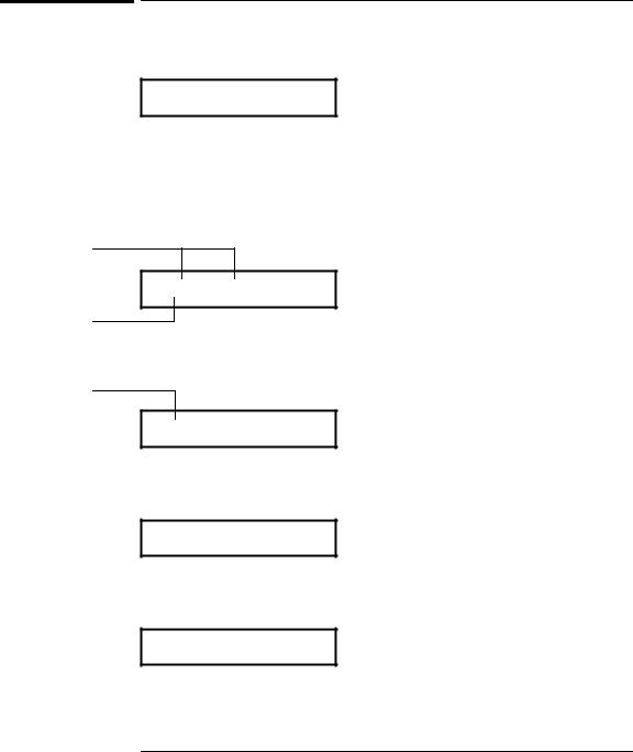
Front-Panel Display Formats
-H.DDD,DDD EFFF
Front-panel display format.
5 digits
10.216,5 VDC
–Negative sign or blank (positive)
H1⁄
“2 ” digit (0 or 1)
DNumeric digits
EExponent ( m, k, M )
FMeasurement units ( VDC, OHM, HZ, dB )
1⁄
“2” digit
This is the 10 Vdc range, 51⁄2 digits are displayed.
1⁄
“2” digit
-045.23 mVDC
This is the 100 mVdc range, 41⁄2 digits are displayed.
113.325,6 OHM
This is the 100 ohm range, 61⁄2 digits are displayed.
OVL.D mVDC
This is an overload indication on the 100 mVdc range.
22
Chapter 1 Quick Start
To Rack Mount the Multimeter
1
To Rack Mount the Multimeter
You can mount the multimeter in a standard 19-inch rack cabinet using one of three optional kits available. Instructions and mounting hardware are included with each rack-mounting kit. Any Agilent System II instrument of the same size can be rack-mounted beside the 34401A.
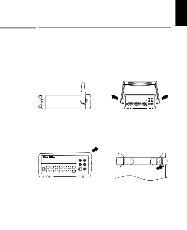
Remove the carrying handle, and the front and rear rubber bumpers, before rack-mounting the multimeter.
To remove the handle, rotate it to the vertical position and pull the ends outward.
Front |
Rear (bottom view) |
To remove the rubber bumper, stretch a corner and then slide it off.
23
Chapter 1 Quick Start
To Rack Mount the Multimeter
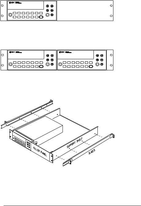
To rack mount a single instrument, order adapter kit 5063-9240.
To rack mount two instruments side-by-side, order lock-link kit 5061-9694 and flange kit 5063-9212.
To install one or two instruments in a sliding support shelf, order shelf 5063-9255, and slide kit 1494-0015 (for a single instrument, also order filler panel 5002-3999).
24
Loading...