


 Loading...
Agilent Technologies 22A, 41A, 24A, 54621D, 42A User Manual
...User’s Guide
Publication Number 54622-97029
March 2002
For Safety Information and Regulatory information, see the pages behind the Index.
©Copyright Agilent Technologies 2000-2002 All Rights Reserved
Agilent 54621A/22A/24A/41A/42A Oscilloscopes and
Agilent 54621D/22D/41D/42D Mixed-Signal Oscilloscopes

The Oscilloscopes at a Glance
Choose from a variety of oscilloscopes for capturing long, non-repeating signals
with 200 MSa/s sample rate and 2 MBytes of MegaZoom deep memory per channel.
•Agilent 54621A - 2-channel, 60-MHz bandwidth
•Agilent 54621D - 2-channel +16 logic channels, 60MHz bandwidth
•Agilent 54622A - 2-channel, 100-MHz bandwidth
•Agilent 54622D - 2-channel +16 logic channels, 100-MHz bandwidth
•Agilent 54624A - 4-channel, 100-MHz bandwidth
with 2 GSa/s sample rate and 4 MBytes of MegaZoom deep memory per channel.
•Agilent 54641A - 2-channel, 350-MHz bandwidth
•Agilent 54641D - 2-channel +16 logic channels, 350-MHz bandwidth
•Agilent 54642A - 2-channel, 500-MHz bandwidth
•Agilent 54642D - 2-channel +16 logic channels, 500-MHz bandwidth
Display shows current input signals
•All analog and digital (54621D/22D/41D/42D) channels displayed in main and delayed mode
•Indicators for channel, time base, digital (54621D/22D/41D/42D) channel activity, trigger and acquisition status
•Softkey labels
•Measurement results
Digital channel controls select, position, and label inputs (54621D/22D/41D/42D)
•Turn channels on or off individually or in groups of 8
•Rearrange order of channels to group related signals
•Create and display labels to identify channels
Run control keys begin and end data acquisition
•Run/Stop starts and stops continuous acquisitions
•Single performs one acquisition
•Infinite persistence accumulates and displays the results of multiple acquisitions
General controls measure, save and restore results, and configure the oscilloscope
•Waveform math including FFT, subtract, multiply, integrate, and differentiate
•Use Quick Meas to make automatic measurements Integrated counter included with Quick Meas.
•Use cursors to make manual measurements
•Save or recall measurement configurations or previous results
•Autoscale performs simple one-button setup of the oscilloscope
Horizontal Controls select sweep speed and delay parameters
•Sweep speeds from 5 ns/div to 50 ns/div (54620series) and 1 ns/div to 50 s/div (54640-series)
•Delay control moves waveform display to point of interest
•Delayed mode and delay allow zooming in to show a portion of waveform in detail (split screen)
Trigger keys define what data the oscilloscope will trigger on
•Source key allows conventional oscilloscope triggering
•Modes include Edge, Pulse Width, Pattern, CAN, Duration, I2C, Sequence, SPI, TV, and USB triggering
Softkeys extend the functionality of command keys
Select measurement types, operating modes, trigger specifications, label data, and more
Digital channel inputs through a flexible probing system (54621D/22D/41D/42D)
•Sixteen channels through a dual 8-channel cable with micro-clips
•Set logic levels as TTL, CMOS, ECL, or to a userdefinable voltage
Utilities
•Dedicated parallel printer port, controller operation, floppy disk storage
Built in Quick Help system
•Press and hold any key front-panel key or softkey to get help in 11 languages.
ii

In This Book
This manual will guide you in using the oscilloscopes. This manual is organized in the following chapters:
Chapter 1 Getting Started—inspecting, cleaning, and setting up your oscilloscope, using Quick Help.
Chapter 2 Front-panel Overview—A quick start guide to get you familiarize you with the front-panel operation.
Chapter 3 Triggering the Oscilloscope—how to trigger the oscilloscope using all the various modes.
Chapter 4 MegaZoom Concepts and Oscilloscope Operation—acquiring waveforms, horizontal and vertical operation, using digital channels.
Chapter 5 Making Measurements—capturing data, using math function, making measurement with cursors and automatic measurements.
Chapter 6 Utilities—configuring the I/O, print settings, Quick Help, floppy disk operations, user cal and self cal, setting the clock and screen saver.
Chapter 7 Performance Characteristics
iii

iv

Contents
1 Getting Started |
|
|
Setting up the Oscilloscope |
1-4 |
|
To inspect package contents |
1-5 |
|
To inspect options and accessories |
1-8 |
|
To clean the oscilloscope 1-11 |
|
|
To adjust the handle 1-12 |
|
|
To power-on the oscilloscope |
1-13 |
|
To adjust the waveform intensity |
1-14 |
|
To connect the oscilloscope analog probes 1-15 |
||
To compensate your analog probe |
1-16 |
|
To use the digital probes (mixed-signal oscilloscope only) 1-17 To connect a printer 1-21
To connect an RS-232 cable 1-21
To verify basic oscilloscope operation 1-22
Getting started using the oscilloscope interface 1-23
Using Quick Help 1-25
Selecting a language for Quick Help when the oscilloscope starts up 1-25 Selecting a language for Quick Help after you have been operating the
oscilloscope 1-26 |
|
|
|
|
Loading an updated language file from floppy disk |
1-27 |
|||
2 Front-Panel Overview |
|
|
|
|
Important Oscilloscope Considerations |
2-3 |
|
||
54620/40-series Oscilloscope Front Panels |
2-7 |
|
||
Front-Panel Operation |
2-10 |
|
|
|
Interpreting the display |
2-11 |
|
|
|
To use analog channels to view a signal |
2-12 |
|
||
To use digital channels to view a signal |
2-13 |
|
||
To display signals automatically using Autoscale |
2-14 |
|||
To apply the default factory configuration |
2-15 |
|
||
To adjust analog channel vertical scaling and position 2-16 To set the vertical expand reference for the analog signal 2-17
Contents-1

Contents
To set analog channel probe attenuation factor |
2-17 |
||||
To display and rearrange the digital channels |
2-18 |
||||
To operate the time base controls |
2-19 |
|
|||
To start and stop an acquisition |
2-20 |
|
|||
To make a single acquisition |
2-20 |
|
|
||
To use delayed sweep |
2-21 |
|
|
|
|
To make cursor measurements |
2-22 |
|
|||
To make automatic measurements |
2-23 |
|
|||
To modify the display grid |
2-24 |
|
|
|
|
To print the display |
2-24 |
|
|
|
|
3 Triggering the Oscilloscope |
|
|
|||
Selecting Trigger Modes and Conditions |
3-3 |
||||
To select the Mode and Coupling menu 3-3 |
|
||||
To select a trigger mode: Normal, Auto, Auto Level 3-4 To select trigger Coupling 3-6
To select Noise Reject and HF Reject 3-6 To set holdoff 3-7
External Trigger Input 3-9
Trigger Types 3-11
To use Edge triggering |
3-12 |
|
|
To use Pulse Width triggering |
3-14 |
||
To use Pattern triggering |
3-17 |
|
|
To use CAN triggering |
3-19 |
|
|
To use Duration triggering |
3-21 |
||
To use I2C triggering |
3-24 |
|
|
To use Sequence triggering |
3-29 |
||
To use SPI triggering |
3-35 |
|
|
To use TV triggering |
3-40 |
|
|
To use USB triggering |
3-50 |
|
|
The Trigger Out connector |
3-52 |
||
Contents-2

Contents
4MegaZoom Concepts and Oscilloscope Operation
MegaZoom Concepts 4-3
Deep Memory |
4-4 |
|
|
Oscilloscope Responsiveness |
4-5 |
||
Display Update Rate |
4-6 |
|
|
To setup the Analog channels |
4-7 |
||
To setup the Horizontal time base 4-11 |
|||
Acquisition Modes |
4-17 |
|
|
Display modes |
4-21 |
|
|
Pan and Zoom |
4-23 |
|
|
To pan and zoom a waveform |
4-24 |
||
Run/Stop/Single/Infinite Persistence Operation 4-25
Acquiring Data 4-26 |
|
|
Memory Depth/Record Length |
4-27 |
|
To run and stop an acquisition |
4-28 |
|
To take a single trace 4-28 |
|
|
To capture a single event |
4-29 |
|
To use infinite persistence |
4-30 |
|
To use infinite persistence to store multiple repetitive events 4-30 To clear the waveform display 4-31
Configuring the Mixed-Signal Oscilloscope |
4-32 |
||
To display digital channels using Autoscale |
4-32 |
|
|
Interpreting the digital waveform display |
4-33 |
|
|
To display and rearrange the digital channels 4-34 |
|||
To turn individual channels on and off |
4-35 |
|
|
To force all channels on or all channels off |
4-36 |
|
|
To change the display size of the digital channels |
4-36 |
||
To change the logic threshold for digital channels |
4-37 |
||
Using Digital Channels to Probe Circuits |
4-38 |
|
|
Using Labels on the Mixed-Signal Oscilloscope 4-42
To turn the label display on or off 4-43
To assign a predefined label to a channel 4-44
To define a new label 4-45
To reset the label library to the factory default 4-47
Contents-3

Contents
Saving and Recalling Traces and Setups 4-48
To Autosave traces and setups 4-49
To save traces and setups to internal memory or to overwrite an existing floppy disk file 4-50
To save traces and setups to a new file on the floppy disk 4-51 To recall traces and setups 4-52
Saving (printing) screen images to floppy disk 4-53 Recalling the factory default setup 4-54
5 Making Measurements
Capturing Data 5-3
To use delayed sweep 5-4
To reduce the random noise on a signal 5-6
To capture glitches or narrow pulses with peak detect and infinite
persistence 5-10 |
|
To use the Roll horizontal mode |
5-12 |
To use the XY horizontal mode |
5-13 |
Math Functions |
5-17 |
|
|
|
Math Scale and Offset 5-18 |
|
|
||
Multiply |
5-19 |
|
|
|
Subtract |
5-20 |
|
|
|
Differentiate 5-21 |
|
|
|
|
Integrate |
5-23 |
|
|
|
FFT Measurement |
5-25 |
|
|
|
Cursor Measurements 5-31 |
|
|
||
To make cursor measurements |
5-32 |
|
||
Automatic Measurements 5-37 |
|
|||
Making automatic measurements |
5-38 |
|
||
Making time measurements automatically |
5-39 |
|||
Making Delay and Phase Measurements |
5-43 |
|||
Making voltage measurements automatically 5-45
Making overshoot and preshoot measurements 5-48
Contents-4

Contents
6 Utilities
To configure Quick Help languages 6-3
To update your instrument to the latest application software 6-5
To configure a printer |
6-6 |
|
To use the floppy disk |
6-8 |
|
To set up the I/O port to use a controller 6-9 |
|
|
To set the clock 6-11 |
|
|
To set up the screen saver 6-12 |
|
|
To perform service functions 6-14 |
|
|
To set other options |
6-16 |
|
7 Performance Characteristics |
|
|
Agilent 54620-series Performance Characteristics |
7-3 |
|
Agilent 54640-series Performance Characteristics |
7-13 |
|
Contents-5

Contents-6
1
Getting Started

Getting Started
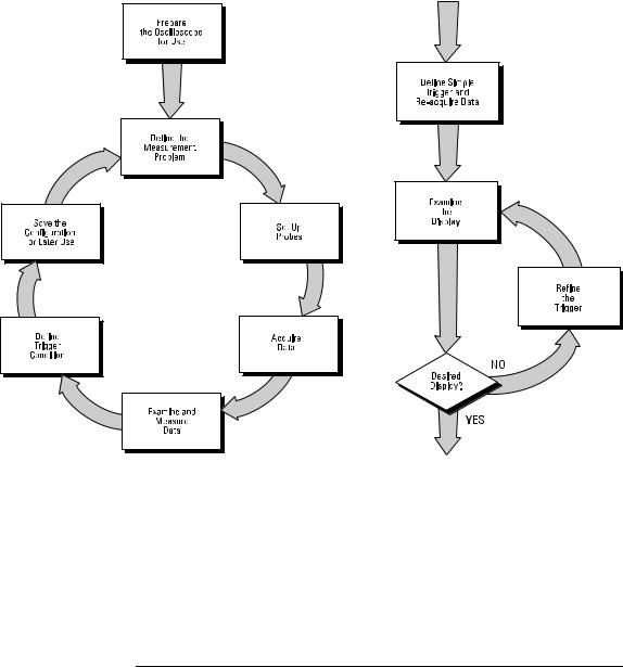
When you use the oscilloscopes to help test and troubleshoot your systems, you may do the following:
•Prepare the oscilloscope by connecting it to power and setting up the handle and screen intensity as desired.
•Define the measurement problem by understanding the parameters of the system you wish to test, and the expected system behavior.
•Set up channel inputs by connecting the probes to the appropriate signal and ground nodes in the circuit under test.
•Define the trigger to reference the waveform data at a specific event of interest.
•Use the oscilloscope to acquire data, either in continuous or singleshot fashion.
•Examine the data and make measurements on it using various features.
•Save the measurement or configuration for later re-use or comparison with other measurements.
Repeat the process as necessary until you verify correct operation or find the source of the problem.
MegaZoom Technology Operates with Untriggered Data
With the MegaZoom technology built into the oscilloscope, you can operate the oscilloscope with untriggered data. All you do is press Run or Single while in Auto trigger mode, then examine the data to set up a trigger.
1-2
Getting Started
The oscilloscope’s high-speed display can be used to isolate infrequently changing signals. You can then use the characteristics of these signals to help refine the trigger specification. For more information on triggering, data acquisition, data examination and measurement, and configuration, see the later chapters.
Using the Oscilloscope, and Refining the Trigger Specification
1-3

Setting up the Oscilloscope
To prepare your oscilloscope for use, you need to do the following tasks. After you have completed them, you will be ready to use the oscilloscope.
In the following topics you will:
•inspect package contents
•inspect options and accessories
•learn how to clean the oscilloscope
•adjust the handle
•power-on the oscilloscope
•adjust the display intensity
•connect the oscilloscope probes
•connect the digital probes (with 54621D/22D/41D/42D)
•connect a printer
•connect a RS-232 cable
•verify basic oscilloscope operation
•get started using the oscilloscope interface
•learn how to use Quick Help
1-4

Getting Started
To inspect package contents
To inspect package contents
Inspect the shipping container for damage.
If your shipping container appears to be damaged, keep the shipping container or cushioning material until you have inspected the contents of the shipment for completeness and have checked the oscilloscope mechanically and electrically.
Verify that you received the following items and any optional accessories in the oscilloscope packaging (see figure following).
•54620/40-Series Oscilloscope:
54621A, 21D, 22A, 22D, 24A, 41A, 41D, 42A, or 42D
•10:1 passive probes with id:
(2) 10074C (150 MHz) for 54621A, 21D, 22A, or 22D
(4) 10074C (150 MHz) for 54624A
(2)10073C (500 MHz) for 54641A, 41D, 42A, or 42D
•54620-68701 digital probe kit for 54621D, 22D, 41D, or 42D
•Accessory pouch and front-panel cover standard for all except 54621A, 21D. (54621A and 21D order N2726A)
•Power cord (see table 1-3)
•IntuiLink for 54600-series Oscilloscopes software and RS-232 cable (all except for 54621A or 21D).
IntuiLink is a Windows application that makes it very easy for you to download images, waveform data, or oscilloscope setups from the oscilloscope to your pc using either Microsoft Word or Microsoft Excel. After installation of IntuiLink, a tool bar in these Microsoft applications will make connection and data transfer from the oscilloscope very simple.
For 54621A and 21D users, IntuiLink for 54600-series Oscilloscopes software is available free on the web at:
www.agilent.com/find/5462xsw
RS-232 cable may be ordered separately, part number 34398A
1-5

Getting Started
To inspect package contents
•Agilent IntuiLink Data Capture (all except for 54621A or 21D)
IntuiLink Data Capture is a standalone program for downloading waveform data from the oscilloscopes to your PC via GPIB or RS-232 interface. It provides the capability to transfer deep memory data out of the oscilloscope, allowing up to 4MB (scope channels) and 8MB (logic channels). The IntuiLink for 54600-Series limits the size of acquisition data available to a maximum of 2,000 points regardless of actual number of acquisition points on the screen. With the IntuiLink Data Capture, the amount of points transferred will be the actual number of acquisition points currently displayed or you may select the number of points to download. It provides the following functionality:
•Download waveform data and display the data as a simple chart
•Save the data as binary or text files
•Copy the chart and a selected portion of the data to the clipboard. The maximum data saved to the clipboard is 50,000 point
•Load saved waveform data back into the application
For 54621A and 21D users, IntuiLink Data Capture software is available free on the web at:
www.agilent.com/find/5462xsw
RS-232 cable may be ordered separately, part number 34398A
If anything is missing, contact your nearest Agilent Sales Office. If the shipment was damaged, contact the carrier, then contact the nearest Agilent Sales Office.
Inspect the oscilloscope
•If there is mechanical damage or a defect, or if the oscilloscope does not operate properly or does not pass the performance tests listed in the Service Guide, notify your Agilent Sales Office.
•If the shipping container is damaged, or the cushioning materials show signs of stress, notify the carrier and your Agilent Sales Office. Keep the shipping materials for the carrier’s inspection. The Agilent Sales Office will arrange for repair or replacement at Agilent’s option, without waiting for claim settlement.
1-6

54620/40-Series Oscilloscope
Accessories pouch and front-panel cover**
Power cord
Getting Started
To inspect package contents
54620-68701 digital probe kit* |
|
54620-61801 16-channel cable |
|
|
5959-9334 2” Ground |
|
|
|
lead (qty 5) |
|
5090-4356 Clip |
|
(qty 20) |
IntuiLink for 54600-series |
10073C or |
|
software, Data Capture |
||
10074C Probes |
||
software and serial cable** |
||
|
s
s1
*54621D /22D/41D/42D only
**All except 54621A/21D
Package contents for 54620/40-Series Oscilloscopes
1-7

Getting Started
To inspect options and accessories
To inspect options and accessories
Verify that you received the options and accessories you ordered and that none were damaged.
If anything is missing, contact your nearest Agilent Sales Office. If the shipment was damaged, or the cushioning materials show signs of stress, notify the carrier and your Agilent Sales Office.
Some of the options and accessories available for the 54620/40-Series Oscilloscopes are listed in tables 1-1 and 1-2. Contact your Agilent Sales Office for a complete list of options and accessories.
Table 1-1 |
Options available |
Option Description
003Shielding Option for use in severe environments or with sensitive devices under test–shields both ways (in and out):
RS-03 magnetic interface shielding added to CRT, and
RE-02 display shield added to CRT to reduce radiated interference.
1CM |
Rackmount kit (same as 1186A) |
A6J |
ANSII Z540 compliant calibration with test data |
W32 |
3-year, customer-return calibration service |
W34 |
3-year, customer-return standard compliance calibration service |
W50 |
Additional 2-year warranty (5 years total) |
W52 |
5-year, customer-return calibration service |
W54 |
5-year customer-return standard compliance calibration service |
|
See table 1-3 for power cord options |
1-8

Getting Started
To inspect options and accessories
Table 1-2 |
Accessories available |
|
|
|
|
|
Model |
Description |
|
1146A |
Current probe, ac/dc |
|
1183A |
Testmobile scope cart |
|
1185A |
Carrying Case |
|
1186A |
Rackmount Kit |
|
10070C |
1:1 Passive Probe with ID |
|
10072A |
Fine-pitch probe kit |
|
10075A |
0.5 mm IC clip kit |
|
10076A |
100:1, 4 kV 250 MHz probe with ID |
|
10085A |
16:16 logic cable and terminator (for use with 54621D/22D/41D/42D) |
|
10089A |
16:2 x 8 logic input probe assembly (shipped standard with 54621D/22D/41D/42D) |
|
10100C |
50Ω Termination |
|
10833A |
GPIB cable, 1 m long |
|
34398A |
RS-232 cable (standard except 54621A/21D) |
|
E2613B |
0.5 mm Wedge probe adapter, 3-signal, qty 2 |
|
E2614A |
0.5 mm Wedge probe adapter, 8-signal, qty 1 |
|
E2615B |
0.65 mm Wedge probe adapter, 3-signal, qty 2 |
|
E2616A |
0.65 mm Wedge probe adapter, 8-signal, qty 1 |
|
E2643A |
0.5 mm Wedge probe adapter, 16-signal, qty 1 |
|
E2644A |
0.65 mm Wedge probe adapter, 16-signal, qty 1 |
|
N2726A |
Accessory pouch and front-panel cover (standard except on 54621A/21D) |
|
N2727A |
Thermal printer and pouch |
|
N2728A |
10 rolls of thermal printer paper |
|
N2757A |
GPIB Interface Module |
|
N2772A |
20 MHz differential probe |
|
N2773A |
Differential probe power supply |
|
N2774A |
50 MHz current probe ac/dc |
|
N2775A |
Power supply for N2774A |
1-9

Getting Started
To inspect options and accessories
Table 1-3. Power Cords
Plug Type |
Cable Part Number |
Plug Type |
Cable Part Number |
||
Opt 900 (U.K.) |
8120-1703 |
Opt 918 (Japan) |
8120-4754 |
||
Opt 901 (Australia) |
8120-0696 |
Opt 919 (Israel) |
8120-6799 |
||
Opt 902 (Europe) |
8120-1692 |
Opt 920 |
(Argentina) |
8120-6871 |
|
Opt 903 |
(U.S.A.) |
8120-1521 |
Opt 921 |
(Chile) |
8120-6979 |
Opt 906 |
(Switzerland) |
8120-2296 |
Opt 922 |
(China) |
8120-8377 |
Opt 912 |
(Denmark) |
8120-2957 |
Opt 927 (Thailand) |
8120-8871 |
|
Opt 917 |
(Africa) |
8120-4600 |
|
|
|
1-10
Getting Started
To clean the oscilloscope
|
To clean the oscilloscope |
1 |
Disconnect power from the instrument. |
|
|
C A U T I O N |
Do not use too much liquid in cleaning the oscilloscope. Water can enter the |
|
front-panel keyboard, control knobs, or floppy disk damaging sensitive |
|
electronic components. |
|
|
2Clean the oscilloscope with a soft cloth dampened with a mild soap and water solution.
3Make sure that the instrument is completely dry before reconnecting to a power source.
1-11
Getting Started
To adjust the handle
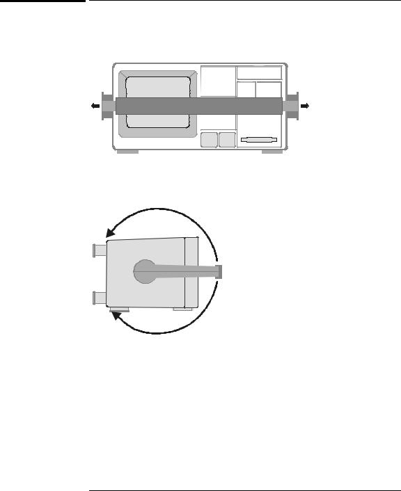
To adjust the handle
1Grasp the handle pivot points on each side of the instrument and pull the pivot out until it stops.
s Agilent |
54622D |
|
|
|
MIXED SIGNAL OSCILLOSCOPE |
|
|
|
|
|
|
|
|
|
|
|
|
|
|
CHANNEL
Time/Div
Select
1 s |
5 ns |
0 15
INPUTS
2Without releasing the pivots, swivel the handle to the desired position. Then release the pivots. Continue pivoting the handle until it clicks into a set position.
1-12
Getting Started
To power-on the oscilloscope
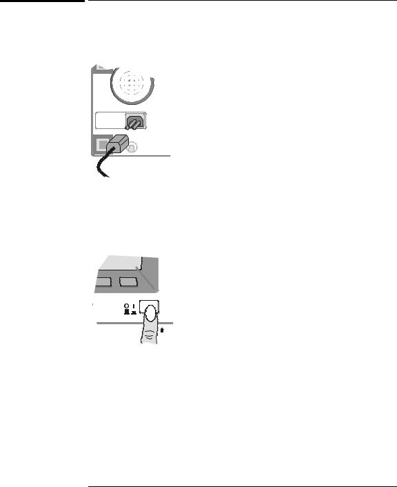
To power-on the oscilloscope
1Connect the power cord to the rear of the oscilloscope, then to a suitable ac voltage source.
The oscilloscope power supply automatically adjusts for input line voltages in the range 100 to 240 VAC. Therefore, you do not need to adjust the input line voltage setting. The line cord provided is matched to the country of origin.
Ensure that you have the correct line cord. See table 1-3
2 Press the power switch.
Some front panel key lights will come on and the oscilloscope will be operational in about 5 seconds.
1-13
Getting Started
To adjust the waveform intensity
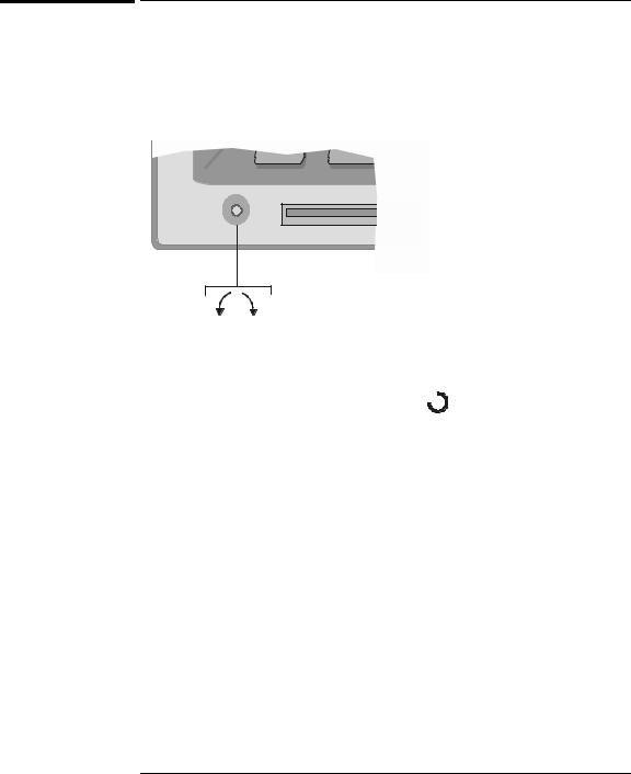
To adjust the waveform intensity
The Intensity control is at the lower left corner of the front panel.
•To decrease waveform intensity, rotate the Intensity control counterclockwise.
•To increase waveform intensity, rotate the Intensity control clockwise.
Figure 1-1
Dim Bright
Intensity control
The grid or graticule intensity on the display can be adjusted by pressing the Display key, then turn the Entry knob (labeled  on the front panel) to adjust the Grid control.
1-14
Getting Started
To connect the oscilloscope analog probes
|
To connect the oscilloscope analog probes |
|
The analog input impedance of these oscilloscopes is selectable either 50Ω |
|
(54640-series only) or 1 MΩ . The 50Ω mode matches 50Ω cables commonly |
|
used in making high frequency measurements. This impedance matching gives |
|
you the most accurate measurements since reflections are minimized along the |
|
signal path. The 1 MΩ mode is for use with probes and for general purpose |
|
measurements. The higher impedance minimizes the loading effect of the |
|
oscilloscope on the circuit under test. |
|
Do not exceed 5 Vrms in 50Ω mode on the 54640-series models. Input |
C A U T I O N |
|
|
protection is enabled in 50Ω mode and the 50Ω load will disconnect if greater |
|
than 5 Vrms is detected. However the inputs could still be damaged, depending |
|
on the time constant of the signal. |
|
The 50Ω input protection mode on the 54640-series models only functions |
C A U T I O N |
|
|
when the oscilloscope is powered on. |
|
|
1Connect the supplied 1.5-meter, 10:1 oscilloscope probe to an analog channel BNC connector input on the oscilloscope.
Maximum input voltage for analog inputs:
CAT I 300 Vrms, 400 Vpk
CAT II 100 Vrms, 400 Vpk
with 10073C or 10074C 10:1 probe: CAT I 500 Vpk, CAT II 400 Vpk
2Connect the retractable hook tip on the probe tip to the circuit point of interest. Be sure to connect the probe ground lead to a ground point on the circuit.
The probe ground lead is connected to the oscilloscope chassis and the ground wire in the power cord. If you need to connect the ground lead to a point in the circuit that cannot be grounded to power ground, consider using a differential probe.
1-15
Getting Started
To compensate your analog probe
To compensate your analog probe
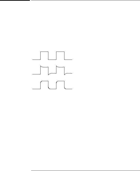
You should compensate you analog probes to match their characteristics to the oscilloscope. A poorly compensated probe can introduce measurement errors. To compensate a probe, follow these steps:
1Connect the probe from channel 1 to the Probe Comp signal on the lowerright corner of the front panel.
2 Press Autoscale.
3Use a nonmetallic tool to adjust the trimmer capacitor on the probe for the flattest pulse possible.
Perfectly compensated
Over compensated
Under compensated
comp.cdr
1-16
Getting Started
To use the digital probes (mixed-signal oscilloscope only)
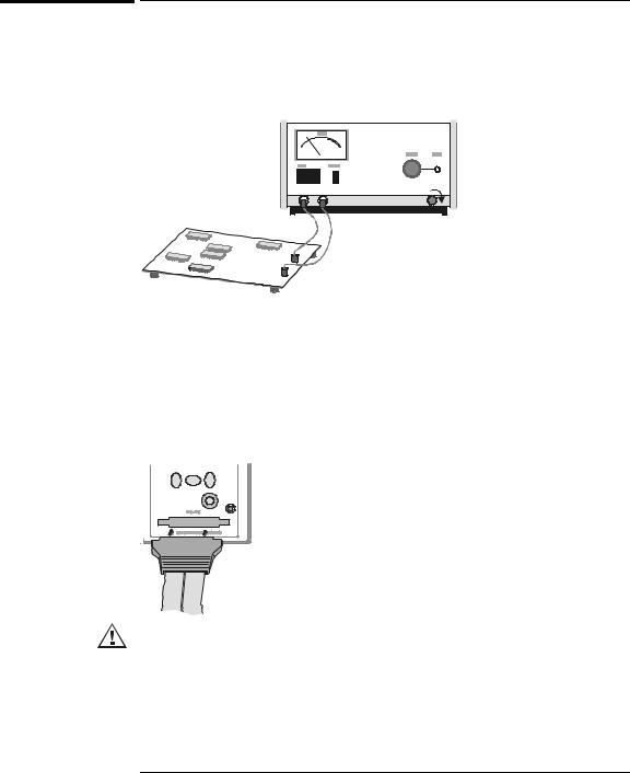
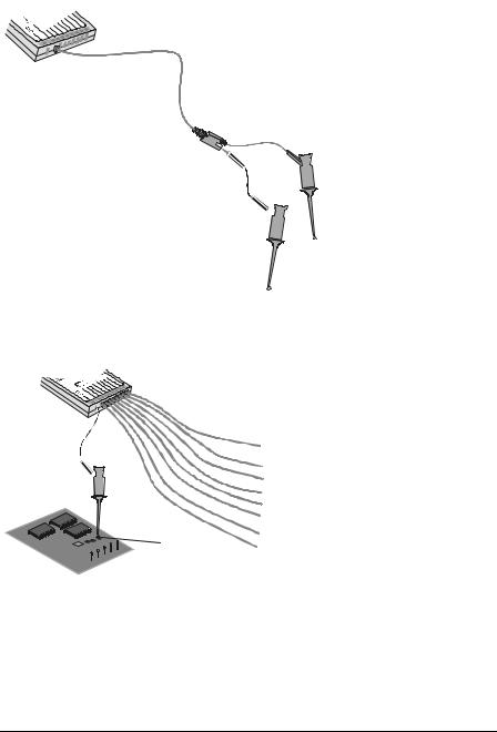
To use the digital probes (mixed-signal oscilloscope only)
1If you feel it’s necessary, turn off the power supply to the circuit under test.
Off
Turning off power to the circuit under test would only prevent damage that might occur if you accidentally short two lines together while connecting probes. You can leave the oscilloscope powered on because no voltage appears at the probes.
2Connect the digital probe cable to D15 - D0 connector on the front panel of the mixed-signal oscilloscope. The digital probe cable is indexed so you can connect it only one way. You do not need to power-off the oscilloscope.
Use only the Agilent part number 54620-68701 digital probe kit supplied with the mixed-signal oscilloscope. Additional probe kits may be ordered by specifying Agilent part number 10089A.
1-17
Getting Started
To use the digital probes (mixed-signal oscilloscope only)
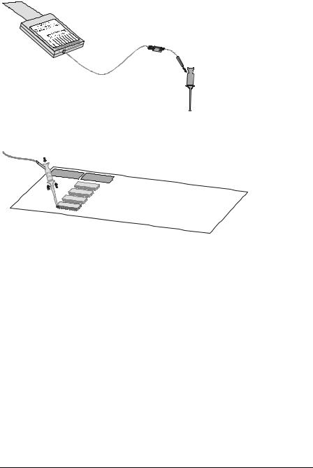
3Connect a clip to one of the probe leads. Be sure to connect the ground lead. (Other probe leads are omitted from the figure for clarity.)
Clip
4 Connect the clip to a node in the circuit you want to test.
1-18
Getting Started
To use the digital probes (mixed-signal oscilloscope only)
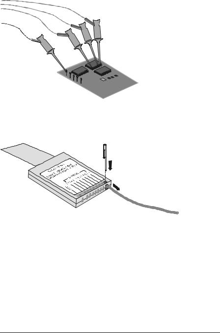
5For high-speed signals, connect a ground lead to the probe lead, connect a clip to the ground lead, and attach the clip to ground in the circuit under test.
Signal Lead
Ground Lead
Clip
6Connect the ground lead on each set of channels, using a probe clip. The ground lead improves signal fidelity to the instrument, ensuring accurate measurements.
Channel
Pod Ground
Circuit
Ground
1-19
Getting Started
To use the digital probes (mixed-signal oscilloscope only)
7 Repeat steps 3 through 6 until you have connected all points of interest.
Signals
Ground
8If you need to remove a probe lead from the cable, insert a paper clip or other small pointed object into the side of the cable assembly, and push to release the latch while pulling out the probe lead.
Replacement parts are available. See the Replaceable Parts chapter in the Service Guide for details.
1-20
Loading...