


 Loading...
Service Guide
Publication Number 54845-97008
February 2001
This manual applies directly to Infiniium oscilloscopes with serial number prefixes:
• XX3625 through XX4106 and above
for information about serial numbers, see “Instruments Covered by this Guide” in section 1.
The part number for this Service Guide
For Safety information, Warranties, and Regulatory information, see the pages at the back of this book.
Copyright Agilent Technologies 1997-2001 All Rights Reserved.
Agilent Model 54835A/45A/46A Oscilloscopes

The Agilent Technologies Infiniium Oscilloscope Model 54835A/45A/46A at a
Glance
Ease of use with high performance
The Agilent Technologies Infiniium oscilloscopes combine unprecedented ease-of-use with highperformance digitizing oscilloscope functionality to simplify your design and analysis measurement tasks.
•Traditional oscilloscope front-panel interface provides direct access to the controls needed for most troubleshooting tasks
•Graphical user interface with menus, windows, dialogs, and toolbars provides easy access to dozens of configuration and analysis tools, ensuring you can set up and make the most complex measurements
•Agilent 54835A offers 4 channels, 4 GSa/s sampling rate in 2-channel mode, 2 GSa/s sampling rate in 4-channel mode, 1 GHz bandwidth
•Agilent 54845A offers 4 channels, 8 GSa/s sampling rate in 2-channel mode, 4 GSa/s sampling rate in 4-channel mode, 1.5 GHz bandwidth
•Agilent 54846A offers 4 channels, 8 GSa/s sampling rate in 2-channel mode, 4 GSa/s sampling rate in 4-channel mode, 2.25 GHz bandwidth
Display shows waveforms and graphical user interface
•Graphical interface allows direct interaction with waveforms, including drag-and-drop positioning and instant waveform zoom
•Waveforms displayed in color, making correlation easy
•Current configuration parameters displayed near the waveform display and are colorcoded to make identification easy
•Graphical interface menus and toolbars simplify complex measurement setups
Horizontal controls set sweep speed and position
•Main sweep speeds from 100 ps/div to 5 s/div
•Delayed sweep speeds from 1 ps/div to main time base setting
•Intensified waveforms on main sweep window make it easy to see what will appear in delayed sweep window
Acquisition and general controls start and stop the scope and do basic setup
•Run and stop controls for continuous or single-shot acquisitions
•Clear display before one or more acquisitions
•Default setup and Autoscale set initial configuration
Hard disk drive and floppy disk drive for saving and restoring setups and measurement results
•Store measurement displays for inclusion in reports and test setup guides
•Store oscilloscope setups to repeat tests another time
•Hard disk stores oscilloscope operating system
Trigger setup controls set mode and basic parameters
•Select Edge, Glitch, or Advanced Modes
•Choose input source and slope
•Set coupling for trigger
•Use graphical user interface to simplify configuration of pattern, state, delay, violation, and video triggers
•Use auxiliary trigger to increase triggering flexibility
Vertical controls set input coupling, impedance, attenuation, and position
•AC or DC input coupling
•1 MΩ or 50Ω input impedance
•Input attenuation adjustable from 2 mV/div to 1 V/div (plus 2 V/div in 1 MΩ)
•Color-coded knobs make it easy to find the controls that affect each waveform
Marker and quick measurements help measure waveform parameters
•Waveform markers A and B to check voltage or ∆−time at any point on the displayed waveform
•Quick Meas executes up to four predefined measurements instantly
Service Policy
The service policy of this instrument requires replacing defective assemblies. Some assemblies can be replaced on an exchange basis. Items such as the vertical attenuators, which are subject to wear and tear based on frequency of use, are a maintenance item that may need occasional replacement.
ii

|
Horizontal |
Acquisition and |
|
|
Display and |
controls |
general controls |
|
Floppy Disk Drive |
|
||||
Graphical |
|
|
|
|
Interface |
|
|
|
|
|
|
|
|
|
|
|
|
|
|
|
|
|
|
Trigger |
|
|
|
|
Setup |
Power |
Marker and Quick |
|
Vertical |
Auxiliary |
|
Inputs |
|||
|
Measurements |
Vertical |
AutoProbe |
Trigger Input |
|
|
|
||
|
|
Controls |
|
|
|
|
Interface |
|
|
|
|
|
|
iii

In This Book
This book provides the service documentation for the Agilent Technologies 54835A/45A/46A oscilloscope. It is divided into eight chapters.
Chapter 1 provides general information and specifications.
Chapter 2 shows you how to prepare the oscilloscope for use.
Chapter 3 gives performance tests.
Chapter 4 covers calibration and adjustment procedures, how to do them, and how often they need to be done.
Chapter 5 provides troubleshooting information.
Chapter 6 gives the procedures and techniques for replacing assemblies and other parts.
Chapter 7 includes a list of exchange assemblies and other replaceable parts, part ordering information, and shipping information.
Chapter 8 briefly covers the internal operation of the oscilloscope.
At the back of the book you will find Safety information, Warranties, and Regulatory information.
iv

Contents
Contents 1
1General Information 1-2
Instruments covered by this service guide 1-2 Accessories supplied 1-3
Options available 1-4 Accessories available 1-5
Specifications & characteristics 1-7
Agilent Technologies 54835A/45A/46A general characteristics 1-14 Recommended test equipment 1-16
2Preparing for Use 2-2
Setting Up the Oscilloscope |
2-3 |
|
To inspect the instrument |
2-3 |
|
To connect power 2-4 |
|
|
To connect the mouse or other pointing device 2-5 |
||
To attach the optional trackball |
2-5 |
|
To connect the keyboard 2-7 |
|
|
To connect to the LAN card |
2-7 |
|
To connect oscilloscope probes |
2-8 |
|
To connect a printer 2-9 |
|
|
To connect an external monitor |
2-10 |
|
To connect the GPIB cable |
2-10 |
|
To tilt the oscilloscope upward for easier viewing 2-11 |
||
To power on the oscilloscope 2-12 |
||
To verify basic oscilloscope operation 2-13 |
||
To clean the instrument 2-14 |
|
|
To clean the display monitor contrast filter 2-14 |
||
3 Testing Performance 3-2
Testing Interval 3-2
Equipment Required 3-2
Self-Test Verification 3-2
Test Record 3-3
Operating Hints 3-3
Specifications 3-3
Performance Test Procedures 3-3
To test the dc calibrator |
3-4 |
To test input resistance |
3-6 |
To test voltage measurement accuracy 3-7
To test offset accuracy 3-11
To test bandwidth 3-13
To test time measurement accuracy 3-16
To test trigger sensitivity 3-23
4Calibrating and Adjusting 4-2
Equipment Required 4-2
Self Calibration Interval and Hardware Adjustments 4-2
Contents-1

Contents
Mainframe Cal Factor Memory Error 4-2 Operating Hints 4-3
Loading Default Oscilloscope Settings 4-3 Loading New Software 4-3
Calibration Procedures 4-3
To check the power supply 4-4
To check the 715 Hz auxiliary output (probe compensation squarewave) 4-6 To check the flat panel display (FPD) 4-7
To run the self calibration 4-10
5 Troubleshooting 5-2
Safety 5-2 |
|
Tools Required 5-2 |
|
ESD Precautions 5-2 |
|
Keystroke Conventions 5-2 |
|
Default Setup 5-3 |
|
To install the fan safety shield |
5-3 |
To troubleshoot the instrument |
5-4 |
Primary Trouble Isolation 5-6 |
|
No Display Trouble Isolation 5-9 |
|
Power Supply Trouble Isolation |
5-13 |
To check probe power outputs |
5-16 |
To check the keyboard 5-17 |
|
To check the LEDs 5-19 |
|
To check the motherboard, CPU, and RAM 5-21 |
|
To check the SVGA display board video signals 5-22 To check the backlight inverter voltages 5-23 POST Code Listing (AMI Motherboard only) 5-24
To configure the motherboard jumpers and set up the BIOS 5-29 To troubleshoot the acquisition system 5-49
To troubleshoot attenuator failures 5-56 Software Revisions 5-59
6Replacing Assemblies 6-2
ESD Precautions 6-2
Tools Required 6-2
To return the instrument to Agilent Technologies for service 6-3 To remove and replace the cover 6-4
To disconnect and connect Mylar flex cables 6-5 |
|
To remove and replace the AutoProbe assembly |
6-6 |
To remove and replace the probe power and control assembly 6-8 |
|
To remove and replace the backlight inverter board 6-9 |
|
To remove and replace the front panel assembly |
6-9 |
To remove and replace the keyboard and flat-panel display assemblies 6-12 To remove and replace the acquisition board assembly 6-14
To remove and replace the LAN interface board |
6-15 |
To remove and replace the GPIB interface board |
6-16 |
To remove and replace the scope interface board and SVGA display board 6-17 To separate the scope interface board and SVGA display board 6-18
To remove and replace the Option 200 sound card 6-19 To remove and replace the hard disk drive 6-20
Contents–2

Contents
To remove and replace the floppy disk drive 6-21
To remove and replace the motherboard |
6-21 |
|
To remove and replace the power supply |
6-24 |
|
To remove and replace the fan |
6-25 |
|
To remove and replace the CPU |
6-26 |
|
To remove and replace RAM SIMMs or SDRAM DIMMs 6-27
To remove and replace an attenuator 6-28
To reset the attenuator contact counter 6-30
To remove and replace an acquisition hybrid 6-32
7Replaceable Parts 7-2
Ordering Replaceable Parts 7-2
Power Cables and Plug Configurations 7-3 Exploded Views 7-4
Replaceable Parts List 7-15
8Theory of Operation 8-3
Block-Level Theory 8-3 Attenuator Theory 8-7 Acquisition Theory 8-7
Contents–3

1
Instruments covered by this service guide 1-2 Accessories supplied 1-3
Options available 1-4 Accessories available 1-5
Specifications & characteristics 1-7
Agilent Technologies 54835A/45A/46A general characteristics 1-14 Recommended test equipment 1-16
General Information

General Information
This chapter of the Agilent Technologies Infiniium Oscilloscope Service Guide gives you general information about the instrument. The following topics are covered in this chapter.
• Instrument identification
• Options
• Accessories
• Specifications and characteristics
• Test equipment requirements
Instruments covered by this service guide
On the rear panel of the instrument is a serial number label and a VIN # label. The serial number is in the form of XX00000000 while the VIN # is in the form of VIN # 0XX. The serial number is composed of two parts: the first two letters and the first four numbers are the serial prefix, while the last four numbers are the suffix. The prefix is normally the same for all identical oscilloscopes and changes only when a change has been made to the oscilloscope. However, the suffix is sequentially assigned and is different for each oscilloscope. The contents of this manual applies to oscilloscopes with serial number prefixes listed on the title page.
An oscilloscope manufactured after the printing of this manual may have a newer serial number prefix. This newer serial prefix indicates that the oscilloscope may be different from those described in this manual. The manual for this oscilloscope will be revised as needed. If you have an oscilloscope with a newer serial prefix, please refer to the Agilent Technologies website and download a newer manual edition in Adobe Acrobat (pdf) format. The Agilent Technologies URL is: “www.agilent.com”. It will be necessary to search on a key word such as “Infiniium Service Guide”, and follow the links.
For additional information on configuration differences see the following sections in this service guide:
• “To configure the motherboard jumpers and setup the BIOS” in the Troubleshooting section 5 for information on determining:
|
|
•which computer configuration is contained in your oscilloscope |
|
|
|
•setting up the BIOS correctly for that configuration |
|
|
|
•setting the motherboard jumpers if the PC motherboard is changed. |
|
|
• Replaceable Parts section 7. |
||
|
|
This section contains exploded views for the different motherboard configurations, cabling |
|
|
|
schemes, and outside hardware versions. The Replaceable Parts List also contains the |
|
|
|
assembly part numbers for the different oscilloscope configurations. |
|
Table 1-1 |
|
|
|
Oscilloscopes Covered by this Service Guide |
|||
|
|
|
|
|
|
Model |
Description |
|
|
Agilent 54846A |
Four-channel digitizing oscilloscope with 8 GSa/s sample rate in 2-channel mode, 4 |
|
|
|
GSa/s sample rate in 4-channel mode, 2.25 GHz bandwidth |
|
|
Agilent 54845A |
Four-channel digitizing oscilloscope with 8 GSa/s sample rate in 2-channel mode, 4 |
|
|
|
GSa/s sample rate in 4-channel mode, 1.5 GHz bandwidth |
|
|
Agilent 54835A |
Four-channel digitizing oscilloscope with 4 GSa/s sample rate in 2-channel mode, |
|
|
|
2 GSa/s sample rate in 4-channel mode, 1 GHz bandwidth |
The oscilloscope can be identified by the product number on the back panel.
1–2

Chapter 1: General Information
Accessories supplied
Accessories supplied
The following accessories are supplied.
•Agilent Mouse, Agilent P/N C3751-60201
•Agilent Mouse Pad, Agilent P/N 54810-85903
•1 Keyboard
•(4) Agilent 1161A 10:1 10 MΩ passive probes
•Accessory Pouch (Agilent P/N 54810-68701)
•Power cord (see chapter 7, “Replaceable Parts,” for available power cords)
•User's Quick Start Guide
•Programmer’s Guide and Programmer’s Quick Reference
•Agilent Technologies Infiniium Oscilloscope Service Guide for Agilent Models 54835A/45A/46A (this manual)
1–3
Chapter 1: General Information
Options available
Options available
The following options are available for the Agilent Technologies Infiniium oscilloscope.
Table 1-2 |
Agilent Technologies Infiniium Oscilloscope Model 54835A/45A/46A Options |
||
|
|
|
|
|
|
Option Number |
Description |
|
090 |
Delete standard probes |
|
|
001 |
Add 2 standard probes—Agilent 1161A probes for the Agilent 54835A/45A/46A |
|
|
002 |
Add 1 Agilent 1162A 1:1 passive probe |
|
|
003 |
Add 1 Agilent 1163A 10:1 500 Ω, low-C passive probe |
|
|
006 |
Add 1 Agilent 1152A 2.5 GHz, 0.6 pF active probe |
|
|
007 |
Add 1 Agilent E2613A, 0.5 mm wedge kit assembly |
|
|
008 |
Add 1 Agilent 1153A 200 MHz differential probe |
|
|
009 |
Add 1 Agilent 1154A 500 MHz differential probe |
|
|
010 |
Add 1 Agilent 1159A 1 GHz differential probe |
|
|
100 |
Communication Mask Test Kit |
|
|
200 |
VoiceControl Option |
|
|
|
1BP |
MIL-STD-45662A and ANSI/NCSL Z540 calibration with test data |
|
|
1CM |
Add 1 Rackmount kit (Agilent E2609A) |
|
|
UL6 |
Add 1 Clip-on trackball pointing device (Agilent E2611A) |
|
|
UL5 |
Add 1 touchpad pointing device (Agilent E2612A) |
|
|
W32 |
3 years calibration service |
|
|
W34 |
3 years return standards comp cal service |
|
|
W50 |
5 years return repair service (additional 2 years) |
|
|
W52 |
5 years return calibrations service |
|
|
W54 |
5 years return standards comp cal service |
Other options are available. See your Agilent Technologies Sales Representative. You can order multiple options, or you can order most of these options separately, using the Agilent model number or part number.
1–4

Chapter 1: General Information
Accessories available
Accessories available
The following accessories are available for use with the Agilent Technologies Infiniium oscilloscope.
Table 1-3 |
Accessories for the Agilent Technologies Infiniium Oscilloscope Model 54835A/45A/46A |
|
|
|
|
|
Agilent 1144A |
800 MHz Active Probe |
|
|
Requires Agilent 1142A power supply—Agilent 1144-61604 probe power extender also |
|
|
required when using 2 or more Agilent 1144A active probes |
|
Agilent 1144-61604 |
Power Probe Extender |
|
Agilent 1145A |
2-channel 750 MHz SMT active probe |
|
|
Requires Agilent 1142A power supply |
|
Agilent 1146A |
Oscilloscope AC/DC Current Probe |
|
Agilent 1152A |
2.5 GHz, 10:1, 100 kΩ, 0.6 pF Active Probe |
|
Agilent 1153A |
200 MHz Differential Probe |
|
Agilent 1155A |
750 MHz 2-Channel, Low-Mass Active Probe |
|
Agilent 1161A |
Standard probes for the Agilent 54835A/45A/46A |
|
Agilent 1162A |
1:1 Passive Probe |
|
Agilent 1163A |
10:1 500-Ω, low-C Passive Probe |
|
Agilent 1170A |
500 MHz Low-Mass, miniature 10:1 10 MΩ Passive Probe |
|
Agilent 1171A |
500 MHz Low-Mass, miniature 10:1 10 MΩ Passive Probe |
|
Agilent 1172A |
500 MHz Low-Mass, miniature 20:1 10 MΩ Passive Probe |
|
Agilent 1173A |
500 MHz Low-Mass, miniature 20:1 10 MΩ Passive Probe |
|
Agilent 1182A |
Testmobile |
|
Agilent 10020A |
Resistive Divider Probe Kit |
|
Agilent 10240B |
BNC Blocking Capacitor |
|
Agilent 10833A |
GPIB cable, 1 m |
|
Agilent 10833B |
GPIB cable, 2 m |
|
Agilent 10833C |
GPIB cable, 4 m |
|
Agilent 10833D |
GPIB cable, 0.5 m |
|
Agilent 11094B |
75Ω Feedthrough Termination |
|
Agilent 34810B |
Benchlink Oscilloscope Software |
|
Agilent 34398A + |
RS-232-C printer cable + adapter kit |
|
Agilent 34399A |
|
|
Agilent 54006A |
6 GHz, 10:1 (500 Ω) or 20:1 (1 kΩ), .25 pF |
|
Agilent 01144-61604 |
1:2 probe power fan-out (for use with Agilent 1144A and Agilent 1145A) |
|
Agilent C2950A |
Parallel printer cable, 2 m |
|
Agilent C2951A |
Parallel printer cable, 3 m |
|
Agilent E2610A |
Keyboard |
|
Agilent E2609A |
Rackmount Kit |
|
Agilent E2611A |
Clip-on Track Ball Pointing Device |
1–5

Chapter 1: General Information
Accessories available
Agilent E2612A |
Touchpad Pointing Device |
Agilent E2625A |
Communication Mask Test Kit |
Agilent 54810-68703 |
Service Kit (includes service software and fan safety shield) |
Agilent 54801-00601 |
Fan Safety Shield (clips onto side of chassis with cover removed) |
Agilent E2635A |
Voice Control Retrofit Kit |
Agilent E2636A |
Microphone Replacement |
1–6

Chapter 1: General Information
Specifications & characteristics
Specifications & characteristics
The following tables list the performance specifications and operating characteristics for the Agilent Technologies 54835A/45A/46A oscilloscope. Asterisks (*) denotes warranted specifications, all others are typical. Specifications are valid after a 30 minute warm-up period, and within ± 5 °C from the self-calibration temperature.
Acquisition
Maximum Sample Rate |
Real Time |
Agilent Models |
|
|
54835A — 2-channel mode: 4 GSa/s |
|
|
54835A — 4-channel mode: 2 GSa/s |
|
|
54845A — 2-channel mode: 8 GSa/s |
|
|
54845A — 4-channel mode: 4 GSa/s |
|
|
54846A — 2-channel mode: 8 GSa/s |
|
|
54846A — 4-channel mode: 4 GSa/s |
Maximum Effective Sample Rate |
Equivalent Time |
500 GSa/s |
Memory Depth |
2-channel mode: 65,536 points |
Agilent 54835A, Agilent 54845A, and |
|
4-channel mode: 32,768 points |
Agilent 54846A |
Memory Depth Modes |
Auto |
Optimized for best combination of |
|
|
update rate and display quality. |
|
Manual |
Selectable |
|
|
2-channel mode: from 16 to 65,536 |
|
|
points |
|
|
4-channel mode: from 16 to 32,768 |
|
|
points |
Sampling Modes |
Real Time |
Successive single shot acquisitions. |
|
Equivalent Time |
Random repetitive sampling (higher |
|
|
time resolution at fast sweep speeds). |
Filters |
9-bit Bandwidth Limit filter: BW = (Sample Rate)/20 |
|
|
(Sin x)/x Interpolation: On/Off selectable FIR digital filter. Digital signal |
|
|
processing adds points between acquired data points to enhance |
|
|
measurement accuracy and waveform display quality. |
|
|
BW= Sample Rate/4 |
|
Averaging |
Selectable from 2 to 4096. |
|
1–7

Chapter 1: General Information
Specifications & characteristics
Vertical
Number of Channels |
4 (simultaneous acquisition) |
|
Bandwidth |
Analog Bandwidth (-3dB)* |
50Ω: 1.0 GHz — Agilent 54835A |
|
|
50Ω: 1.5 GHz — Agilent 54845A |
|
|
50Ω: 2.25 GHz — Agilent 54846A |
|
|
1 MΩ: 500 MHz (with Agilent 1161A probe) |
Rise Time1
Sensitivity2
Input Impedance*
VSWR (50 Ω)
Input Coupling
Maximum Input Voltage
Channel-to-channel Isolation (with channels at equal sensitivity)
Offset Range
Full-resolution channel scales
Dynamic Range
dc Gain Accuracy*2
Resolution2
System Bandwidth |
Agilent 1161A 10:1 passive probe: 500 MHz |
|
Agilent 1162A 1:1 passive probe: 25 MHz |
|
Agilent 1163A 10:1, 500 Ω passive probe: |
|
1.5 GHz |
|
Agilent 1152A 2.5 GHz, 0.6 pF active probe: |
|
1.3 GHz (Agilent 54845A) |
|
Agilent 1152A 2.5 GHz, 0.6 pF active probe: |
|
1.0 GHz (Agilent 54835A) |
|
Agilent 1153A 200 MHz differential probe: |
|
200 MHz |
Real Time bandwidth* |
50Ω: |
|
Agilent 54835A — 1 GHz (2-channel mode) |
|
Agilent 54835A — 500 MHz (4-channel mode) |
|
Agilent 54845A — 1.5 GHz (2-channel mode) |
|
Agilent 54845A — 1.0 GHz (4-channel mode) |
|
Agilent 54846A — 2.25 GHz (2-channel mode) |
|
Agilent 54846A — 1.0 GHz (4-channel mode) |
|
1 MΩ: 500 MHz |
50Ω: 350 ps (Agilent 54835A) |
|
50Ω: 233 ps (Agilent 54845A) |
|
50Ω: 156 ps (Agilent 54846A) |
|
1 MΩ: 700 ps |
|
1 MΩ Coupling: 2 mV/div to 2 V/div |
|
50 Ω Coupling: 2 mV/div to 1 V/div |
|
1 MΩ ± 1% ( 12 pf), or 50 Ω ± 1.5% |
|
54835A/45A |
54846A |
dc to 500 MHz: 1.30 |
dc to 500 MHz: 1.30 |
500 MHz to 1 GHz: 1.50 |
500 MHz to 1 GHz: 1.50 |
1 GHz to 1.5 GHz: 1.75 |
1 GHz to 1.5 GHz: 1.75 |
|
1.5 GHz to 2.25 GHz: 2.50 |
dc, ac (7 Hz, available in 1 MΩ only) |
|
1 MΩ: ± 100 V (dc + ac) [ac<10 kHz], CAT I 50 Ω: 5 Vrms, CAT I
54835A/54845A
dc to 100 MHz: 40 dB 100 MHz to 1 GHz: 30 dB 1 GHz to 1.5 GHz: 25 dB
Vertical Sensitivity
1MΩ:
2mV to 104 mV/div
>104 mV to 2 V/div
50Ω: all
54846A
dc to 100 MHz: 40 dB 100 MHz to 1 GHz: 30 dB 1 GHz to 2.25 GHz: 24 dB
Available Offset
±4 V
±40 V
±12 div
10, 20, 50, 100, 200, 500, 1000 mV/div (plus 2000 mV/div in 1 MΩ)
±8 div from center screen
±1.00% of full scale at full-resolution channel scale.
Real Time |
8 bits (0.4% of full scale), 12 bits with |
|
sufficient averaging (0.024% of full scale) |
Equivalent Time |
8 bits (0.4% of full scale), 12 bits with |
|
sufficient averaging (0.024% of full scale) |
1–8

Chapter 1: General Information
Specifications & characteristics
Offset Accuracy*2 |
± (1.00% of channel offset + 1% of full scale) at full-resolution channel scale. |
|
dc Voltage Measurement |
Dual Cursor |
±[(dc gain accuracy)+(resolution)] |
Accuracy*2 |
|
|
|
Single Cursor |
±[(dc gain accuracy) |
|
|
+(offset accuracy)+(resolution/2)] |
AutoProbe Interface |
AutoProbe is an intelligent communication and power link between compatible |
|
|
probes and Infiniium scopes. AutoProbe completely configures the scope for the |
|
|
attached probe. For instance, it identifies the probe type and sets up the proper input |
|
|
impedance, attenuation ratio, probe power and offset range, as needed. |
|
Horizontal
Main Time Base Range |
100 ps/div to 20 s/div |
|
Horizontal Position Range |
pre-trigger |
0 to -1 s or one full screen width, |
|
|
whichever is larger. |
|
post-trigger |
0 to 1 s or one full screen width, |
|
|
whichever is larger. |
Delayed Sweep Range |
1 ps/div to current main time base setting. |
|
Delayed Sweep Delay Range |
Within main time base acquisition record. |
|
Resolution |
2 ps |
|
Timebase Accuracy |
70 ppm (.007%) |
|
∆t Accuracy* |
Real Time mode4 |
±[(.007%)(∆t)+(0.2)(sample period)] |
|
Equivalent Time mode |
±[(.007%)(∆t)+(full scale/ |
|
|
(2 × memory depth)) + 30 ps] |
|
|
(Example: for ≥ 16 avgs, 9 ns signal, |
1 ns/div, 1 channel, then accuracy =
±[(.007%)(9 ns)+(10 ns/(2 × 65,536)) + 30 ps] = 31 ps)
1–9

Chapter 1: General Information
Specifications & characteristics
Trigger
Sensitivity*2 |
Internal |
dc to 100 MHz: 0.5 div |
|
|
100 MHz to 500 MHz: 1.0 div |
|
|
500 MHz to 1 GHz: 1.5 div |
|
Auxiliary |
dc to 500 MHz: 300 mVpp |
Maximum Input Voltage* |
Auxiliary |
±15 V, CAT I |
Minimum Pulse Width |
500 ps at > 1.0 div |
|
(internal, external) |
|
|
Level Range |
Internal |
±8 div from center screen |
|
Auxiliary |
±5 V |
Sweep Modes |
Auto, triggered, single |
|
Trigger Coupling |
dc, ac (7 Hz), low frequency reject (50 kHz), high frequency reject (50 kHz). |
|
Trigger Holdoff Range |
60 ns - 320 ms |
|
Trigger Modes |
Edge, Glitch, Pattern, State, Delay by Time, Delay by Events, Violation ( |
|
|
Setup/Hold Time, Pulse Width, Transition), Video, Line. |
|
Glitch |
Select positive or negative polarity, width. Captures glitches as narrow as 500 ps. |
|
Pattern |
Select inputs as High, Low or X (don’t care) to create pattern. Trigger when |
|
|
pattern is entered, exited, present > t, present < t, or present over a range of |
|
|
time. Captures patterns as narrow as 500 ps. |
|
State |
Select one channel as clock, specify other inputs as High, Low or X. |
|
|
Logic Type: AND or NAND |
|
Delay by Time |
Time: 30 ns to 160 ms. The trigger is qualified by an edge. After the delay, a |
|
|
rising/falling edge on any one selected input will generate the trigger. |
|
Delay by Events |
Events: 1 to 16,000,000 rising or falling edges. The trigger is qualified by an edge. |
|
|
After the delay, a rising/falling edge on any one selected input will generate the |
|
|
trigger. |
|
Violation Trigger |
Setup/Hold |
Modes: Setup, Hold or Setup and Hold. |
|
|
Select Clock, Thresholds, setup and/or |
|
|
hold time. |
|
Pulse Width |
Triggers on pulse width >t, or <t. |
|
|
Captures pulses as narrow as 500 ps. |
|
Transition |
Select Rise Time or Fall Time, |
|
|
present > t or present < t, thresholds. |
Accuracy (time) for glitch, pulse |
1.5 ns - 20 ns: ±(20% setting + 500 ps) |
|
width, and time-qualified pattern |
20 ns - 160 ms: ±(3% setting + 2 ns) |
|
Video Triggering |
525 lines/60 Hz (NTSC), 625 lines/50 Hz (PAL), 875 lines/60 Hz. Trigger on Field 1 |
|
|
or Field 2, any line. User defined triggering: User can specify sync pulse level, |
|
|
width and polarity, edge number. |
|
1–10

Chapter 1: General Information
Specifications & characteristics
Display
Display |
8.4-inch diagonal color active matrix LCD module incorporating amorphous |
|
|
silicon TFTs. |
|
Active Display Area |
171 mm x 128 mm (21,888 sq. mm) |
|
Waveform Viewing Area |
104 mm x 159 mm (16,536 sq. mm) in Full screen mode |
|
|
(graphical user interface off) |
|
Display Resolution |
640 pixels horizontally x 480 pixels vertically |
|
Waveform Colors |
Select from 100 hues, 0-100% saturation and 0-100% luminosity. |
|
Dual Intensity Infinite Persistence |
Previous sweeps are stored in half bright display and most recent sweep in full |
|
|
bright. This allows easy differentiation of current and historic information. |
|
Waveform Overlap |
When two waveforms overlap, a third color distinguishes the overlap area. |
|
Full screen mode |
On/Off selectable. |
|
Connect-the-dots |
On/Off selectable. |
|
Persistence |
Minimum, Variable (100 ms to 40 s), Infinite. Up to 6 levels of grey scale. |
|
Graticule |
On/Off (Grid or Frame). |
|
Grid Intensity |
0 to 100% |
|
Display Update Rate |
Measurement Conditions |
Real Time sampling mode, minimum |
(for instruments equipped with |
|
persistence, triggered sweep, no |
AMD-K6-2 400 MHz processor) |
|
interpolation, markers off, math off, |
|
|
connect the dots off, 1 channel |
|
|
acquisition, 50 ns/div, statistics off. |
|
512 point record (2 GSa/s) |
Waveforms/sec: > 2,100 |
|
|
Vpp Measurements/sec: > 130 |
Measurements
Automatic Parametrics |
33 automatic measurements: Vpp , Vmin , Vmax ,Vavg , Vamptd , Vbase , Vtop, Vrms , |
|
Preshoot, Overshoot, Vupper , Vmiddle , Vlower , Rise Time, Fall Time, Period, |
|
Frequency, Positive Width, Negative Width, Duty Cycle, Delta Time, Tmax , Tmin , |
|
FFT Frequency, FFT Magnitude, FFT Delta Frequency, FFT Delta Magnitude, Eye |
|
Height, Eye Width, Jitter, Crossing %, Q-factor, Duty Cycle Distortion. |
|
Over GPIB only: VTime, TVolts. |
Threshold Definition |
Selectable 10%, 50%, 90% or 20%, 50%, 80% or Custom (% or absolute voltage). |
Top-Base Definition |
Standard or Custom (in absolute voltage). |
Statistics |
On/Off selectable. Current measurement, mean, and standard deviation |
Measurement Toolbar |
16 Drag and Drop automatic measurement icons. |
QuickMeas |
Activates 4 preselected automatic measurements. |
Markers Modes |
Manual Markers, Track Waveform Data, Track Measurements. |
Waveform Math |
4 function waveforms f1-f4. Select from Add, Subtract, Multiply, Divide, Invert, |
|
Magnify, Vs, Min, Max, Integral, Differentiate, FFT Magnitude. |
1–11

Chapter 1: General Information
Specifications & characteristics
FFT
Frequency Range5
Freq. Accuracy Amplitude Display Signal-to-noise ratio
Window Modes
Agilent 54835A — 2-channel mode: dc to 2 GHz (Sample rate/2) Agilent 54835A — 4-channel mode: dc to 1 GHz (Sample rate/2) Agilent 54845A — 2-channel mode: dc to 4 GHz (Sample rate/2) Agilent 54845A — 4-channel mode: dc to 2 GHz (Sample rate/2) Agilent 54846A — 2-channel mode: dc to 4 GHz (Sample rate/2) Agilent 54846A — 4-channel mode: dc to 2 GHz (Sample rate/2)
(1/2 frequency resolution)+(7x10⁻⁵)(signal frequency)
Power in dBm
70 dB at 32K memory depth. Noise floor varies with memory depth and with averaging.
Hanning, Flattop, Rectangular.
Computer System/ Storage
CPU |
AMD-K5™PR133 Microprocessor |
|
(instrument serial numbers US37349999 and below) or |
|
AMD-K6™200 MHz Microprocessor or |
|
AMD-K6/300™ or AMD-K6-2/300™ 300 MHz Microprocessor |
Disk Drive |
1.4 GByte, 2.1 GByte, or higher |
|
internal hard drive depending upon |
|
the vintage. Storage capacity is |
|
limited only by disk space. 3.5", 1.44 |
|
™ |
|
Mbyte MS-DOS -compatible high |
|
density floppy disk drive or LS-120 |
|
MS-DOS 120 MByte floppy disk |
|
drive. |
Store and recall setups, waveforms, and store screen images to both the hard drive and the floppy drive.
File types |
Waveforms |
Internal Y values; X and Y values in ASCII |
|
|
or Microsoft Excel formats. |
|
Images |
BMP, EPS, GIF, PCX, PS (Postscript), TIF. |
Mouse |
Standard mouse supplied—supports any Microsoft® mouse compatible pointing |
|
|
device, serial or PS/2. |
|
Operating System |
Microsoft Windows 95 or Microsoft Windows 98 |
|
Waveform Memories |
4 nonvolatile waveform reference memories. |
|
I/O
LAN |
Enables data/setup file transfers and use of network printers; supports popular |
|
network operating systems including Novell NetWare, Microsoft, Banyan VINES, |
|
SCO UNIX and IBM; 10 Mbps operation that complies with IEEE 802.3 Ethernet and |
|
ISO/IEC 8802-3 Ethernet standards; TCP/IP protocol; RJ-45 connector. |
GPIB |
Fully programmable, complies with IEEE 488.2. |
RS-232 (serial) |
2 ports: COM1, COM2. Printer and pointing device support. |
Centronics |
Printer port. |
USB |
Two pinheads link with Universal Serial Bus connectors (USB1 and USB2) |
|
peripheral devices via either a dual-port USB cable or a single-port USB cable on |
|
some configurations with serial prefixes US39480000 and above. |
Printers and Plotters |
Supports all printers and plotters compatible with Microsoft Windows95®. Includes |
|
but is not limited to Hewlett-Packard Deskjet and Laserjet printers. GPIB devices |
|
not supported. |
PS/2 port |
For PS/2 mouse. |
Keyboard port |
For optional keyboard. |
1–12

Chapter 1: General Information
Specifications & characteristics
Video Output |
15-pin VGA, full color. |
Notes
1Rise Time figures are calculated from: tr=.35/Bandwidth.
2Magnification is used below the 10 mV/div range and between the major attenuation settings. Full scale
is defined as the major attenuator setting over an intermediate setting. (Major settings for 50Ω: 10, 20, 50, 100, 200, 500, 1000 mV
Major settings for 1 MΩ: all as for 50Ω plus 2 V)
3N/A
4For bandwidth limited signals, tr >=1.4 x sample interval.
5FFT amplitude readings are affected by input amplifier roll-off (-3 dB, with amplitude decreasing as frequency increases above 500 MHz in 1 MΩ, 2.25 GHz for Agilent 54846A, 1.5 GHz in 50Ω for Agilent 54845A, 1 GHz in 50Ω for Agilent 54835A).
CAT I and CAT II Definitions
Installation category (overvoltage category) I: Signal level, special equipment or parts of equipment, telecommunication, electronic, etc., with smaller transient overvoltages than installation category (overvoltage category) II.
Installation category (overvoltage category) II: Local level, appliances, portable equipment etc., with smaller transient overvoltages than installation category (overvoltage category) III.
1–13
Chapter 1: General Information
Agilent Technologies 54835A/45A/46A general characteristics
Agilent Technologies 54835A/45A/46A general characteristics
The Infiniium oscilloscopes meet the Agilent Technologies Environmental Specification (section 750) for class B-1 products with exceptions as described for temperature.
General Characteristics
Environmental |
Temperature |
Operating: 10°C to +40°C |
|
|
Nonoperating: –40°C to 70°C |
|
|
Indoor use only |
|
Humidity |
Operating: Up to 95% relative humidity |
|
|
(noncondensing) at +40°C |
|
|
Nonoperating: Up to 90% relative |
|
|
humidity at +65°C |
|
Altitude |
Operating: Up to 4 600 meters |
|
|
Nonoperating: Up to 15 300 meters |
|
Vibration |
Operating: Random vibration 5-500 Hz, |
|
|
10 minutes per axis, 0.3g (rms) |
|
|
Nonoperating: Random vibration 5-500 |
|
|
Hz, 10 minutes per axis, 2.41g (rms) |
|
|
Resonant search 5-500 Hz, swept sine, |
|
|
1 octave/minute sweep rate, (0.75g), |
|
|
5-minute resonant dwell at 4 |
|
|
resonances per axis. |
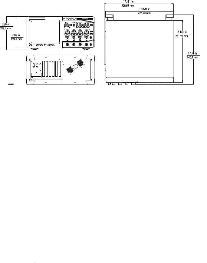
Physical |
Size (excluding handle) |
Height: 216 mm |
|
|
Width: 437 mm |
|
|
Depth: 440 mm |
|
Weight |
Net: approximately 12 kg |
|
|
Shipping: approximately 15 kg |
Power |
Line voltage selection |
None, PFC (Power Factor Correction) |
|
Line voltage range |
100-240VAC, ± 10% CAT II |
|
Line frequency |
47 to 440 Hz |
|
Maximum power consumption |
390 W |
Safety |
Meets IEC1010-1 +A1, CSA certified to C22.2 No. 1010.1, Self certified to UL 3111. |
|
1–14
Chapter 1: General Information
Agilent Technologies 54835A/45A/46A general characteristics
1–15

Chapter 1: General Information
Recommended test equipment
Recommended test equipment
The following table is a list of the test equipment required to test performance, calibrate and adjust, and troubleshoot this instrument. The table indicates the critical specification of the test equipment and for which procedure the equipment is necessary. Equipment other than the recommended model may be used if it satisfies the critical specification listed in the table.
Recommended Test Equipment
Equipment Required |
Critical Specifications |
Recommended Model |
Use * |
Signal Generator |
1 - 2.25 GHz, sine wave, amplitude 30 - 200 |
Agilent 8664A |
P |
|
mVrms, time base accuracy 0.25 ppm |
|
|
RF Amplifier |
22 dB gain at 10 MHz, 1.3 GHz bandwidth |
Agilent 8447D/F |
P |
Power Meter/Power |
1 - 500 MHz, -70 dBm to +44 dBm, ±3% accuracy |
Agilent EPM- |
P |
Sensor |
|
441A/Agilent 8482A |
|
DMM |
6 1/2 digit (0.1 mV) resolution, dcV accuracy |
Agilent 34401A |
P, A, T |
|
8 ppm/year, 4-wire resistance acc. ±0.25% |
|
|
Power Supply |
7 mV - 30 V dc, 0.1 mV accuracy and resolution |
Agilent 6114A |
P |
Power Splitter |
50 Ω type N, outputs differ by <0.15 dB |
Agilent 11667A |
P |
Probe |
No substitute |
Agilent 1161A |
P |
Probe Tip Adapter |
1160 series to BNC |
Agilent 5063-2143 |
P |
Oscilloscope |
General-purpose |
Agilent 54622A |
P, T |
Blocking Capacitor |
0.18 µF |
Agilent 10240B |
P |
Cable |
Type N (m)(m) - 3 foot |
Agilent 11500A or B |
P |
Cable (2) |
BNC - 3 foot |
Agilent 10503A |
P, A, T |
Cable (3) |
BNC - 9 inch |
Agilent 10502A |
P, A, T |
Adapter |
N (m) to BNC (m) |
Agilent 1250-0082 |
P |
Adapter |
N (m) to BNC (f) |
Agilent 1250-0780 |
P |
Adapter |
N (f) to BNC (m) |
Agilent 1250-0077 |
A |
Adapter (2) |
BNC tee (m)(f)(f) |
Agilent 1250-0781 |
P, T |
Adapter |
BNC (f)(f) |
Agilent 1250-0080 |
T |
Adapter (2) |
BNC (f) to dual banana (m) |
Agilent 1251-2277 |
P |
Termination |
BNC connectors 50 Ω |
Agilent 10100C |
P |
Shorting cap |
BNC |
Agilent 1250-0774 |
P |
Resistor (2) |
5 Ω, 5 W |
Agilent 0812-0047 |
T |
Video monitor |
Accepts VGA-standard video signals |
|
T |
Keyboard |
PC-compatible, AT 5-pin connector |
Agilent E2610A |
T |
Mouse |
PS/2 compatible |
Agilent C3751-60201 |
P, T |
POST Card |
Power-on self test card compatible with PC- |
|
T |
|
compatible systems |
|
|
Fan Safety Shield |
Clips onto side of chassis with cover removed |
Agilent 54801-00601 |
A, T |
Service software |
No substitution |
Agilent 54810-68700 |
T |
Note: the Fan Safety Shield and Service software are part of the Service Kit, Agilent P/N 54810-68703. * P = Performance Tests, A = Adjustments, T = Troubleshooting
1–16

2
Setting Up the Oscilloscope 2-3 To inspect the instrument 2-3 To connect power 2-4
To connect the mouse or other pointing device 2-5
To attach the optional trackball |
2-5 |
To connect the keyboard 2-7 |
|
To connect to the LAN card 2-7 |
|
To connect oscilloscope probes |
2-8 |
To connect a printer 2-9 |
|
To connect an external monitor |
2-10 |
To connect the GPIB cable 2-10
To tilt the oscilloscope upward for easier viewing 2-11 To power on the oscilloscope 2-12
To verify basic oscilloscope operation 2-13 To clean the instrument 2-14
To clean the display monitor contrast filter 2-14
Preparing for Use

Preparing for Use
This chapter shows you how to prepare the Agilent Technologies 54835A/45A/46A oscilloscopes for use. The following areas are covered in this section.
•Inspection
•Setup
•Connecting a signal
•Cleaning
Following instrument setup is a brief section covering oscilloscope operation. If you are unfamiliar with this oscilloscope's operation, refer to the User’s Quick Start Guide. The topics covered include:
•Using the front panel
•Using the graphical interface
•Starting and stopping acquisition
•Adjusting oscilloscope configuration
•Making measurements
The Infiniium Oscilloscope is designed to make it easy for you to use a high-performance digitizing oscilloscope.
•The familiar front-panel oscilloscope interface with knobs and buttons is optimized for the most common kinds of troubleshooting tasks and basic measurements.
•The graphical interface with menus, windows, dialogs, and toolbars provides easy logical access to dozens of configuration and analysis tools, making it easy for you to set up and make the most complex measurements.
2–2

Chapter 2: Preparing for Use
To inspect the instrument
Setting Up the Oscilloscope
This section will help you get the instrument ready to use. Included are procedures for:
•Inspection
•Connecting power
•Connecting probes and accessories
•Connecting peripherals
•Verifying basic operation
•Cleaning
To inspect the instrument
Inspect the shipping container for damage.
Keep a damaged shipping container or cushioning material until the contents of the shipment have been checked for completeness and the instrument has been checked mechanically and electrically.
Check the accessories.
Accessories supplied are listed in chapter 1 of this service guide.
•If the contents are incomplete or damaged notify your Agilent Technologies Sales Office.
Inspect the instrument.
•If there is mechanical damage or defect, or if the instrument does not operate properly or pass performance tests, notify your Agilent Technologies Sales Office.
•If the shipping container is damaged, or the cushioning materials show signs of stress, notify the carrier as well as your Agilent Technologies Sales Office. Keep the shipping materials for the carrier's inspection. The Agilent Technologies office will arrange for repair or replacement at Agilent Technologies' option without waiting for claim settlement.
2–3
Chapter 2: Preparing for Use
To connect power
To connect power
The instrument Power Factor Correction (PFC) circuitry in the oscilloscope’s power supply operates over a line voltage in the range of 100 to 240 Vac ±10% (the power supply is autoranging to the input voltage and frequency). Line frequency must be in the range 47 to 440 Hz. Power consumption is 390W maximum.
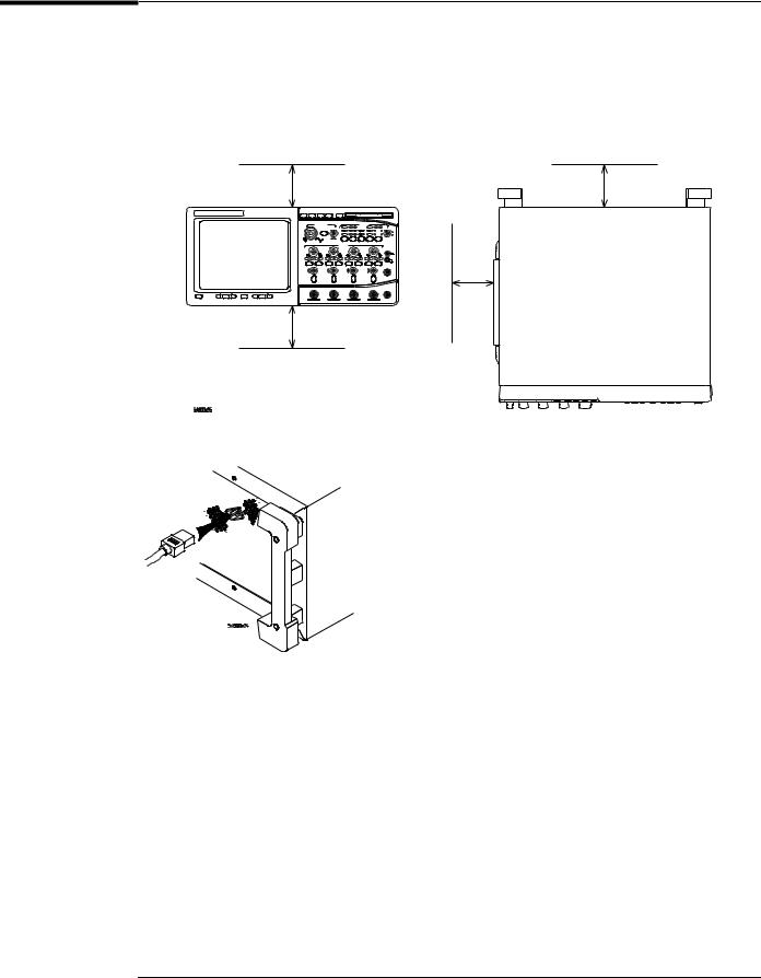
1Position the instrument where it will have sufficient clearance for airflow around the top, back, and sides.
Minimum 0 mm |
|
Minimum 38.1 mm |
|
|
|
|
|
|
|
|
|
|
|
|
Minimum 15.9 mm (maintained by feet; however, do not place on soft surfaces that will impede airflow)
Airflow requirements
Agilent 54835A/45A/46A – 250
Minimum  15.9 mm both sides
2Connect the power cord to the rear of the oscilloscope, then to a suitable ac voltage source.
|
|
The line cord provided is matched by Agilent Technologies to the country of origin of order. |
|
|
Ensure that you have the correct line cord. See “Power Cables and Plug Configurations” in |
|
|
chapter 7. |
|
|
|
WARNING |
|
SHOCK HAZARD! |
|
|
BEFORE YOU CONNECT THIS INSTRUMENT TO MAINS POWER OR LIVE MEASURING |
|
|
CIRCUITS, you must provide a protective earth ground. Failure to provide a protective earth |
|
|
ground could result in a shock hazard if there is a failure in this instrument or equipment |
|
|
connected to it. |
|
|
The mains plug must be inserted in a socket outlet provided with a protective earth contact. |
|
|
Do not use an extension cord (power cable) without a protective conductor (grounding). |
|
|
Grounding one conductor of a two-conductor outlet does not provide an instrument ground. |
|
|
|
|
|
|
|
|
A Three-wire Power Cable is Provided |
|
|
This instrument is provided with a three-wire power cable. When connected to an appropriate ac power |
|
|
outlet, this cable grounds the instrument cabinet. |
|
|
|
2–4
Chapter 2: Preparing for Use
To connect the mouse or other pointing device
To connect the mouse or other pointing device
• Plug the mouse into the matching connector on the back panel of the oscilloscope.
The mouse is included with the oscilloscope, but using it is optional. While you can operate many oscilloscope functions with only the front-panel keys and knobs, you will need the mouse to access advanced oscilloscope functions through the graphical interface, or to find out more about the oscilloscope through the built-in information system.
The optional touchpad pointing device connects in exactly the same way as the mouse.
The supplied mousepad provides the correct surface for smooth mouse operation. To modify the mouse configuration, see the User’s Quick Start Guide.
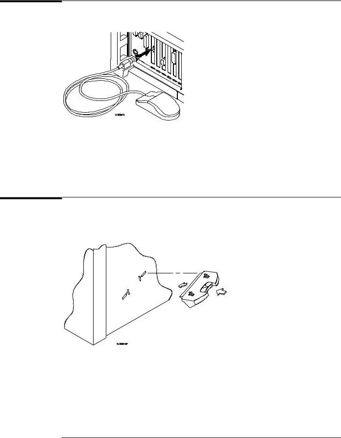
To attach the optional trackball
1Push in the latch on the trackball baseplate to extend the metal tabs. Insert the lower tab into the frontmost slot on the side of the oscilloscope. You can only install the trackball on the right side of the oscilloscope.
2–5
Chapter 2: Preparing for Use
To attach the optional trackball
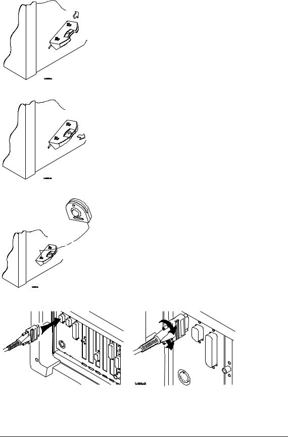
2While holding the latch in, slide the metal tabs up and to the rear of the oscilloscope until they fully engage the slot.
3Release the latch. The trackball baseplate should now be secure against the side of the oscilloscope.
4Snap the trackball assembly onto the pins of the baseplate. The trackball and buttons should face up and toward the front of the oscilloscope.
5Connect the 9-pin “D” connector on the trackball cable to the COM1 port on the back panel. Tighten the retaining screws.
For information on changing the trackball settings, see the User’s Quick Start Guide.
2–6

Chapter 2: Preparing for Use
To connect the keyboard
To connect the keyboard
•Plug the keyboard cable into the matching connector on the back panel of the oscilloscope.
The keyboard simplifies access to some oscilloscope functions, such as entering file names when you store waveforms and setups to the disk. If you need to free desk space, place the keyboard on top of the instrument. Do not stack other objects on the keyboard; this will cause self-test failures on power-on.
To connect to the LAN card
•Connect your LAN cable to one of the connectors on the LAN card. Make sure the connection is secure. Two connections are possible on the LAN card: the RJ-45 connection and a BNC connection. Units equipped with 10/100Base-T LAN cards have an RJ-45 connector only.
RJ-45 Connection
BNC Connection
Each Infiniium Oscilloscope now ships with a LAN card installed. If you want a LAN connection, but have an older Infiniium Oscilloscope model that does not have a LAN card installed, contact your Agilent Technologies Sales and Service Office. An Agilent Technologies LAN Card Installation Kit with instructions is available from Agilent Technologies, and describes how to add a LAN card to your Infiniium Oscilloscope. After you have connected to the LAN card, you must set up the network as described in the User’s Quick Start Guide.
2–7
Loading...