


 Loading...
Agilent 1100 Series
Quaternary Pump
Reference Manual
sa

Copyright Agilent
Technologies 1999
All rights reserved. Reproduction, adaption, or translation without prior written permission is prohibited, except as allowed under the copyright laws.
Part No. G1311-90003
Edition 01/00
Printed in Germany
Warranty
The information contained in this document is subject to change without notice.
Agilent Technologies makes no warranty of any kind with regard to this material, including, but not limited to, the implied warranties or merchantability and fitness for a particular purpose.
Agilent Technologies shall not be liable for errors contained herein or for incidental or consequential damages in connection with the furnishing, performance, or use of this material.
WARNING
For details of safety, see Safety Information on page 260.
Warning Symbols Used
In This Book
!
The apparatus is marked with this symbol when the user should refer to the instruction manual in order to protect the apparatus against damage.
Agilent Technologies
Hewlett-Packard-Strasse 8
76337 Waldbronn
Germany

Agilent 1100 Series Quaternary Pump
Reference Manual

In This Book
This manual contains technical reference information about the Agilent 1100 Series quaternary pump. The manual describes the following:
•installation,
•optimizing performance,
•troubleshooting,
•repairing,
•parts and materials,
•theory of operation, and
•specifications.
4

Contents
1 Installing the Pump |
|
|
How to install the quaternary pump |
13 |
|
Site Requirements 14 |
|
|
Unpacking the Quaternary Pump |
17 |
|
Optimizing the Stack Configuration |
20 |
|
Installing the Quaternary Pump |
22 |
|
Flow Connections of the Quaternary Pump 25 |
||
Priming and Purging the System |
28 |
|
2 Optimizing Performance
How to optimize the quaternary pump to achieve best chromatographic results 31
Hints for Successful Use of the Quaternary Pump 32 Solvent Information 34
Prevent Blocking of Solvent Filters 35 Operational Hints for the Vacuum Degasser 36
Operational Hints for the Multi Channel Gradient Valve (MCGV) 37
When to use the Continuous Seal Wash Option 38 When to Use Alternative Seals 39
Optimize the Compressibility Compensation Setting 40
3Troubleshooting and Test Functions
The quaternary pump’s built-in troubleshooting and test functions 43
Status Indicators 45
5

Contents
Power Supply Indicator |
46 |
|
|||
Pump Status Indicator |
46 |
|
|||
Error Messages |
47 |
|
|
|
|
Timeout 48 |
|
|
|
|
|
Shut-Down |
49 |
|
|
|
|
Remote Timeout |
50 |
|
|
|
|
Synchronization Lost |
51 |
|
|
||
Leak 52 |
|
|
|
|
|
Leak Sensor Open |
53 |
|
|
||
Leak Sensor Short |
54 |
|
|
||
Compensation Sensor Open |
55 |
||||
Compensation Sensor Short |
56 |
||||
Fan Failed |
57 |
|
|
|
|
Open Cover |
58 |
|
|
|
|
Restart Without Cover |
59 |
|
|||
Zero Solvent Counter |
60 |
|
|
||
Pressure Above Upper Limit |
61 |
||||
Pressure Below Lower Limit |
62 |
||||
Pressure Signal Missing |
63 |
|
|||
Missing Pressure Reading |
64 |
||||
Pump Configuration |
65 |
|
|
||
Valve Fuse |
66 |
|
|
|
|
Inlet-Valve Fuse 67 |
|
|
|
||
Valve Failed |
68 |
|
|
|
|
Motor-Drive Power 69 |
|
|
|||
Encoder Missing |
70 |
|
|
|
|
Inlet-Valve Missing |
71 |
|
|
||
Temperature Out of Range 72 |
|||||
Temperature Limit Exceeded |
73 |
||||
Servo Restart Failed |
74 |
|
|
||
6

Contents
Pump Head Missing |
75 |
|
||
Index Limit |
76 |
|
|
|
Index Adjustment |
77 |
|
||
Index Missing |
78 |
|
|
|
Stroke Length |
79 |
|
|
|
Initialization Failed |
80 |
|
||
Wait Timeout |
|
81 |
|
|
Pressure Test |
82 |
|
||
Running the Pressure Test 84 |
||||
Evaluating the Results |
86 |
|||
Leak Test |
88 |
|
|
|
Running the Leak Test |
90 |
|||
Evaluating the Results |
92 |
|||
4Repairing the Pump
Instructions on simple, routine repair procedures as well as more extensive repairs requiring exchange of internal
parts 97 |
|
Cleaning the Quaternary Pump |
99 |
Using the ESD Strap 100 |
|
Overview 101 |
|
Simple Repair Procedures |
102 |
Exchanging the Active Inlet Valve Cartridge or the Active Inlet Valve 103
Exchanging the Outlet Ball Valve 106
Exchanging the Purge Valve Frit or the Purge Valve 108
7

Contents
Removing and Disassembling the Pump Head Assembly |
110 |
||||
Exchanging the Pump Seals and Seal Wear-in Procedure |
112 |
||||
Exchanging the Plungers |
115 |
|
|
|
|
Installing the Continuous Seal Wash Option 116 |
|
||||
Exchanging the Wash Seals |
119 |
|
|
|
|
Reassembling the Pump Head Assembly |
121 |
|
|||
Exchanging the Multi-Channel Gradient Valve (MCGV) |
123 |
||||
Exchanging the optional Interface Board |
126 |
|
|||
Exchanging Internal Parts |
127 |
|
|
|
|
Removing the Top Cover and Foam |
128 |
|
|
||
Exchanging the Low Pressure Pump Main Board (LPM |
|
||||
Board) 131 |
|
|
|
|
|
Exchanging the Damper |
138 |
|
|
|
|
Exchanging the Fan 141 |
|
|
|
|
|
Exchanging the Pump Drive |
143 |
|
|
|
|
Exchanging the Power Supply 147 |
|
|
|
||
Exchanging the Leak Sensor |
152 |
|
|
|
|
Exchanging the Status Light Pipe |
154 |
|
|
||
Assembling the Main Cover |
155 |
|
|
|
|
Replacing the Top Cover and Foam |
156 |
|
|
||
5Parts and Materials
Detailed illustrations and lists for identification of parts and materials 159
Overview of Main Assemblies 160
Control Module (B-version) 163
Solvent Cabinet 164
8

Contents
Bottle Head Assembly |
165 |
||
Hydraulic Path |
166 |
|
|
Cover Parts |
167 |
|
|
Sheet Metal Kit |
168 |
|
|
Foam Parts |
169 |
|
|
Power and Status Light Pipes 170 |
|||
Leak Parts |
171 |
|
|
Pump Head Assembly |
172 |
||
Pump Head Assembly with Seal Wash Option 174
Outlet Ball Valve Assembly |
176 |
||||
Purge Valve Assembly |
177 |
|
|||
Active Inlet Valve Assembly |
178 |
||||
Accessory Kit G1311-68705 |
179 |
||||
Seal Wash Option Kit 01018-68722 180 |
|||||
Cable Overview |
181 |
|
|
||
Analog Cables |
183 |
|
|
||
Remote Cables |
185 |
|
|
||
BCD Cables |
190 |
|
|
|
|
Auxiliary Cable |
|
192 |
|
|
|
CAN Cable |
192 |
|
|
|
|
External Contact Cable |
193 |
|
|||
RS-232 Cable Kit |
194 |
|
|
||
LAN Cables |
195 |
|
|
|
|
6Introduction to the Quaternary Pump
An introduction to the pump, instrument overview, theory of operation, external communication and internal
connectors 197
9

Contents
Introduction to the Quaternary Pump |
198 |
|
Overview 199 |
|
|
Electrical Connections |
204 |
|
Instrument Layout 206 |
|
|
Early Maintenance Feedback (EMF) |
207 |
|
The Electronics 209 |
|
|
The Low-Pressure Pump Main Board (LPM) 210 |
||
Firmware Description |
214 |
|
Optional Interface Boards 216 |
|
|
Agilent 1100 Series Interfaces 218 |
|
|
Setting the 8-bit Configuration Switch |
223 |
|
The Main Power Supply Assembly 228
7 Control Module Screens for the Quaternary Pump
Screens available from the Analysis screen |
233 |
Screens available from the System screen |
242 |
Screens available from the Records screen |
244 |
Diagnostics and Tests 251 |
|
8 Specifications
Performance specifications of the quaternary pump 253
Performance Specifications 254
Warranty Statement 257
Safety Information 260
Lithium Batteries Information 263
10
Contents
Radio Interference 264
Sound Emission 264 Solvent Information 265
Agilent Technologies on Internet 266
11

Contents
12

1
Installing the Pump
How to install the quaternary pump

WA R NI N G
WA R NI N G
WA R NI N G
WA R NI N G
Installing the Pump
Site Requirements
Site Requirements
A suitable environment is important to ensure optimum performance of the quaternary pump.
Power Consideration
The quaternary pump power supply has wideranging capability (see Table 1 on page 16). It accepts any line voltage in the range described in the above mentioned table. Consequently there is no voltage selector in the rear of the quaternary pump. There are also no externally accessible fuses, because automatic electronic fuses are implemented in the power supply.
To disconnect the quaternary pump from line, unplug the power cord. The power supply still uses some power, even if the power switch on the front panel is turned off.
Shock hazard or damage of your instrumentation can result, if the devices are connected to a line voltage higher than specified.
Power Cords
Different power cords are offered as options with the quaternary pump. The female end of each of the power cords is identical. It plugs into the power-input socket at the rear of the quaternary pump. The male end of each of the power cords is different and designed to match the wall socket of a particular country or region.
Never operate your instrumentation from a power outlet that has no ground connection. Never use a power cord other than the power cord designed for your region.
Never use cables other than the ones supplied by Agilent Technologies to ensure proper functionality and compliance with safety or EMC regulations.
14

N O T E
CA U T IO N
Installing the Pump
Site Requirements
Bench Space
The quaternary pump dimensions and weight (see Table 1 on page 16) allow to place the quaternary pump on almost any laboratory bench. It needs an additional 2.5 cm (1.0 inches) of space on either side and approximately 8 cm (3.1 inches) in the rear for the circulation of air and electric connections.
If the bench should carry a complete Agilent 1100 Series system, make sure that the bench is designed to carry the weight of all the modules.
The pump should be operated in a horizontal position!
Environment
Your quaternary pump will work within specifications at ambient temperatures and relative humidity as described in Table 1 on page 16.
Do not store, ship or use your quaternary pump under conditions where temperature fluctuations could cause condensation within the quaternary pump. Condensation will damage the system electronics. If your quaternary pump was shipped in cold weather, leave it in its box and allow it to warm slowly to room temperature to avoid condensation.
15

Installing the Pump
Site Requirements
Table 1 |
Physical Specifications |
|
|
|
|
|
|
Type |
|
Specification |
Comments |
Weight |
|
11 kg (25 lbs) |
|
Dimensions |
|
140 × 345 × 435 mm |
|
(height × weight × depth) |
|
(5.5 × 13.5 × 17 inches) |
|
|
|
|
|
Line voltage |
|
100–120 or 220–240 VAC, ± 10% |
Wide-ranging capability |
Line frequency |
|
50 or 60 Hz, ± 5% |
|
Power consumption |
|
220 VA |
Maximum |
|
|
|
|
Ambient operating temperature |
4–55 °C (41–131 °F) |
|
|
Ambient non-operating temperature |
-40–70 °C (-4–158 °F) |
|
|
Humidity |
|
< 95%, at 25–40 °C (77–104 °F) |
Non-condensing |
Operating Altitude |
|
Up to 2000 m (6500 ft) |
|
Non-operating altitude |
|
Up to 4600 m (14950 ft) |
For storing the quaternary |
|
|
|
pump |
Safety standards: IEC, CSA, UL |
Installation Category II, Pollution Degree 2 |
|
|
|
|
|
|
16

CA U T IO N
Table 2
Installing the Pump
Unpacking the Quaternary Pump
Unpacking the Quaternary Pump
Damaged Packaging
Upon receipt of your quaternary pump, inspect the shipping containers for any signs of damage. If the containers or cushioning material are damaged, save them until the contents have been checked for completeness and the quaternary pump has been mechanically and electrically checked. If the shipping container or cushioning material is damaged, notify the carrier and save the shipping material for the carrier’s inspection.
If there are signs of damage to the quaternary pump, please do not attempt to install the quaternary pump.
Delivery Checklist
Ensure all parts and materials have been delivered with the quaternary pump. The delivery checklist is shown in Table 2. To aid in parts identification, please see Chapter 5 “Parts and Materials”. Please report missing or damaged parts to your local Agilent Technologies sales and service office.
Quaternary Pump Checklist
Description |
Quantity |
|
|
|
|
Quaternary pump |
1 |
|
Solvent cabinet |
1 |
(5062-8581) |
Solvent bottles |
4 |
(3 transparent 9301-1420, 1 amber 9301-1450) |
Bottle head assembly |
4 |
(G1311-60003) |
Waste tube, purge valve |
1 |
(5042-2461, reorder number, 5m) |
Vacuum degasser |
1 |
|
Solvent tubes for the |
4 |
(G1322-67300) |
degasser |
|
|
Power cables |
2 |
|
17

Installing the Pump
Unpacking the Quaternary Pump
Table 2 |
Quaternary Pump Checklist, continued |
|
|
||
|
|
|
|
|
|
|
Description |
Quantity |
|
|
|
|
|
|
|
|
|
|
CAN cable |
1 |
|
|
|
|
Remote cable |
As ordered |
|
|
|
|
Signal cable |
As ordered |
|
|
|
|
Reference Manual |
2 (1 for the pump, 1 for the degasser) |
|||
|
Accessory kit (see Table 3) |
1 |
|
|
|
|
|
|
|
||
|
Accessory Kit Contents — Quaternary Pump |
|
|
||
|
|
|
|
||
Table 3 |
Accessory Kit Contents G1311-68705 |
|
|
||
|
|
|
|
|
|
|
Description |
|
Part Number |
Quantity |
|
|
|
|
|
|
|
|
Capillary, pump to injection device |
G1312-67305 |
1 |
|
|
|
Seal insert tool |
|
01018-23702 |
1 |
|
|
Wrench; 1/4 – 5/16 inch |
|
8710-0510 |
1 |
|
|
Wrench; 14 mm |
|
8710-1924 |
1 |
|
|
ESD wrist strap* |
|
9300-1408 |
1 |
|
|
Hex key 4mm |
|
8710-2392 |
1 |
|
|
Waste tube (reorder number, 5m) |
5062-2463 |
1.2 m |
||
|
Velocity regulator (reorder number) |
5062-2486 |
2 |
|
|
|
PTFE Frit |
|
01018-22707 |
5 |
|
|
|
|
|
|
|
* ESD: Electrostatic Discharge
18

Installing the Pump
Unpacking the Quaternary Pump
Accessory Kit Contents—Vacuum Degasser
Table 4 |
Accessory Kit Contents G1322-68705 |
|
|
|
|
|
|
|
Description |
Part Number |
Quantity |
|
|
|
|
|
Syringe |
5062-8534 |
1 |
|
Syringe adapter |
9301-1337 |
1 |
|
Waste tube (reorder number, 5m) |
5062-2463 |
1.2 m |
|
Connecting tubes labeled A to D |
G1322-67300 |
4 |
|
|
|
|
19
Installing the Pump
Optimizing the Stack Configuration
|
Optimizing the Stack Configuration |
|
If your quaternary pump is part of a complete 1100 Series system, you can |
|
ensure optimum performance by limiting the configuration of the system |
|
stack to the following configuration. This configuration optimizes the system |
|
flow path, ensuring minimum delay volume. |
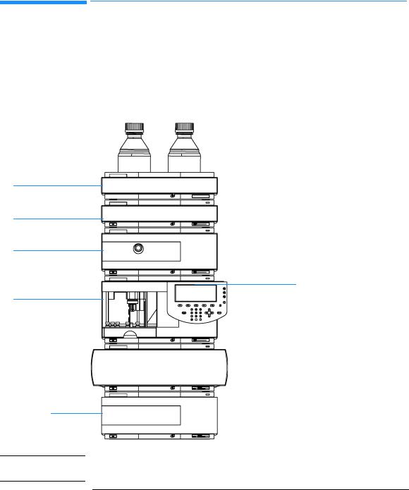
Figure 1 |
Recommended Stack Configuration (Front View) |
Solvent cabinet
Vacuum degasser
Quaternary pump
Autosampler
Flow connections in the stack:
Example setup with 0.17mm ID green capillaries
Solvent bottles - degasser:
G1311-60003 (bottle-head assembly, PTFE-tubings)
Degasser - pump:
G1322-67300 (PTFE-tubings)
Pump - autosampler:
G1312-67305 (SST, green)
Pump purge valve - waste:
5062-2461 (PTFE tubing wide bore, reorder pack)
Control Module
Autosampler - column compartment:
G1313-87305 (SST, green)
Column compartment - column:
|
G1316-87300 (SST, green) |
|
Column - detector: |
Column compartment |
|
|
DAD G1315-87311 (SST, coated) |
|
VWD 5062-8522 (PEEK) |
|
Detector - waste: |
Detector
N O T E
DAD 0890-1713 (PTFE, wide bore) VWD 5062-8535 (PEEK)
5062-2463 (corrugated waste tubing, reorder pack)
For a detailed view of the flow connections refer to the section “Flow Connections” in chapter 1 of the reference manuals of the individual modules.
20
Installing the Pump
Optimizing the Stack Configuration
Figure 2 |
Recommended Stack Configuration (Rear View) |
Remote cable 5061-3378
Pressure output to recorder, for
PN see page 181
CAN Bus cable to handheld controller G1323-81600
CAN Bus cable for inter module communication 5181-1516 (0.5m)
5161-1519 (1.0m)
|
|
AC power |
|
Analog signal to |
|
|
|
recorder,for |
|
|
|
PN see page 181 |
|
|
|
|
|
GPIB or |
|
|
|
LAN to ChemStation |
|
|
|
for PN see page 181 |
|
|
|
|
|
|
|
|
|
N O T E |
If a single stack configuration becomes too high, e.g. if an additional module |
||
|
like a G1327A ALS Thermostat is added or if your bench is to high, a two stack |
||
|
configuration may be a better setup. Separate the stack between pump and |
||
|
autosampler and place the stack containing the pump on the right side of the |
||
|
stack containing the autosampler. |
||
|
|
|
|
21

Installing the Pump
Installing the Quaternary Pump
|
Installing the Quaternary Pump |
|
|
Preparations |
Locate bench space. |
|
Provide power connections. |
|
Unpack the pump. |
Parts required |
Pump |
|
Power cord, for other cables see text below and “Cable Overview” on page 181 |
|
ChemStation and/or Control Module G1323A/B |
|
|
1Place the quaternary pump on the bench in a horizontal position.
2Ensure the power switch on the front of the quaternary pump is OFF (switch stands out).
Figure 3 |
Front of Quaternary Pump |
Status Lamp
Power Switch
Serial number
3At the rear of the quaternary pump move the security lever to its maximum right position.
4Connect the power cable to the power connector at the rear of the quaternary pump. The security lever will prevent that the cover is opened while the power cord is connected to the quaternary pump.
5Connect the required interface cables to the quaternary pump.
22
|
|
Installing the Pump |
|
|
|
Installing the Quaternary Pump |
|
|
|
|
|
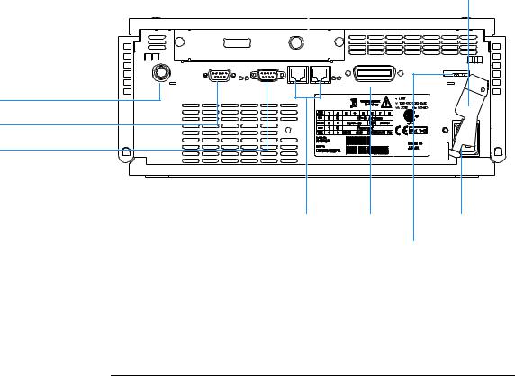
N O T E |
In an Agilent 1100 Series system, the individual modules are connected |
||
|
|
through CAN cables. The Agilent 1100 Series vacuum degasser is an exception |
|
|
|
. The vacuum degasser can be connected via the APG remote connector to the |
|
|
|
other modules of the stack. The AUX output allows the user to monitor the |
|
|
|
vacuum level in the degasser chamber. An Agilent 1100 Series control module |
|
|
|
can be connected to the CAN bus at any of the modules in the system except |
|
|
|
for the degasser. The Agilent ChemStation can be connected to the system |
|
|
|
through one GPIB or LAN (requires the installation of a LANboard) cable at |
|
|
|
any of the modules (except for the degasser), preferably at the detector |
|
|
|
(MUST for the DAD). For more information about connecting the control |
|
|
|
module or Agilent ChemStation refer to the respective user manual. For |
|
|
|
connecting the Agilent 1100 Series equipment to non-Agilent 1100 Series |
|
|
|
equipment, see Chapter 6 “Introduction to the Quaternary Pump” |
|
|
|
|
|
Figure 4 |
Rear of Quaternary Pump |
||
|
|
|
Security lever |
|
|
|
|
|
Slot for interface board |
|
|
|
|
|
|
Analog pressure, 2mV/bar |
APG Remote |
RS-232C |
CAN
GPIB |
Power |
Configuration switch |
|
6Connect all capillaries, solvent tubes and waste tubing (see “Flow Connections of the Quaternary Pump” on page 25).
7Press in the power switch to turn on the quaternary pump.
23

Installing the Pump
Installing the Quaternary Pump
N O T E |
The power switch stays pressed in and a green indicator lamp in the power |
|
switch is on when the quaternary pump is turned on. When the line power |
|
switch stands out and the green light is off, the quaternary pump is turned off. |
|
|
8Purge the quarternary pump (see “Priming and Purging the System” on page 28).
WA R NI N G |
To disconnect the quaternary pump from line, unplug the power cord. |
|
The power supply still uses some power, even if the power switch on |
|
the front panel is turned off. |
|
|
|
|
N O T E |
The pump was shipped with default configuration settings. To change these |
|
settings, see “Setting the 8-bit Configuration Switch” on page 223. |
|
|
24
Installing the Pump
Flow Connections of the Quaternary Pump
|
|
Flow Connections of the Quaternary Pump |
||
|
|
|
|
|
Preparations |
|
Pump is installed in the LC system. |
||
Parts required |
|
Other modules |
||
|
|
Parts from accessory kit, see “Accessory Kit Contents — Quaternary Pump” on page 18 |
||
|
|
Two wrenches 1/4–5/16 inch for capillary connections |
||
|
|
|
|
|
|
|
|
|
|
WA R NI N G |
|
When opening capillary or tube fittings solvents may leak out. Please |
||
|
|
observe appropriate safety procedures (for example, goggles, safety |
||
|
|
gloves and protective clothing) as described in the material handling |
||
|
|
and safety data sheet supplied by the solvent vendor, especially when |
||
|
|
toxic or hazardous solvents are used. |
||
|
|
|
|
|
|
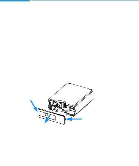
1 Remove the front cover by pressing the snap fasteners on both sides. |
|||
Figure 5 |
|
Removing the Front Cover |
||
|
|
|
|
|
|
|
|
|
|
2Place the vacuum degasser and the solvent cabinet on top of the quaternary pump.
3Put the bottle-head assemblies into solvent reservoirs containing your mobile phase and place the bottle in the solvent cabinet.
4Connect the inlet tubes from the bottle-head assemblies to the inlet connectors A to D (typically the left connection of the channel) of the vacuum degasser. Fix the tubes in the tube clips of the vacuum degasser.
25

Installing the Pump
Flow Connections of the Quaternary Pump
5Connect the solvent tubes to the outlet connectors (typically right connection of the channel) of the vacuum degasser.
6Connect the syringe adapter from the degasser accessory kit to the solvent tube of channel A.
7Using a piece of sanding paper connect the waste tubing to the purge valve and place it into your waste system.
8If the quaternary pump is not part of a Agilent1100 System stack or placed on the bottom of a stack, connect the corrugated waste tube to the waste outlet of the pump leak handling system.
9Connect the pump outlet capillary (quaternary pump to injection device) to the outlet of the purge valve.
10Prime your system before first use (see “Priming and Purging the System” on page 28).
26

Installing the Pump
Flow Connections of the Quaternary Pump
Figure 6 |
Flow Connections of the Quaternary Pump |
Bottle-head assembly (G1311-60003)
Solvent cabinet
Vacuum degasser
Inlet
Outlet
Tube clip (1400-1578)
Tubings (G1322-67300)
Purge valve
Waste tubing (5062-2461)
Outlet capillary to autosampler (G1312-67305)
MCGV
Fitting for corrugated waste tubing (5062-2463, reorder pack, 5m)
27

Installing the Pump
Priming and Purging the System
Priming and Purging the System
The system can be primed either by drawing solvent through the degasser with a syringe or by pumping with the pump.
Priming the system with a syringe is recommended, when:
•vacuum degasser or connected tubings are used for the first time or vacuum tubes are empty or
•changing to solvents that are immiscible with the solvent currently in the vacuum tubes.
|
Priming the system by using the pump at high flow rate |
|
(3–5 ml/min) is recommended, when: |
|
• pumping system was turned off for a length of time (for example, |
|
overnight) and if volatile solvent mixtures are used, or |
|
• solvents have been changed. |
|
|
WA R NI N G |
When opening capillary or tube fittings solvents may leak out. Please |
|
observe appropriate safety procedures (for example, goggles, safety |
|
gloves and protective clothing) as described in the material handling |
|
and safety data sheet supplied by the solvent vendor, especially when |
|
toxic or hazardous solvents are used. |
|
Priming with a Syringe |
|
|
|
Before using a new degasser or new tubings for the first time: |
1Prime all tubings with at least 30 ml of iso-propanol no matter whether the channels will be used with organic mobile phase or with water.
If you are changing to a solvent that is immiscible with the solvent currently in the tubing continue as follows:
2Replace the current solvent with adequate organic solvent (see Table 5 on page 30), if current solvent is organic or with water, if current solvent is an inorganic buffer or contains salt.
3Disconnect solvent outlet tube of the channel that is supposed to be primed from your pump.
4Connect syringe adapter to solvent outlet tube.
28

Installing the Pump
Priming and Purging the System
5Push syringe adapter onto syringe.
6Pull syringe plunger to draw at least 30 ml of solvent through degasser and tubing.
7Replace the priming solvent with the new solvent of your choice.
8Pull syringe plunger to draw at least 30 ml of solvent through degasser and tubing.
9Disconnect syringe adapter from solvent tube.
10Connect the solvent tube to the appropriate channel of the MCGV.
11Repeat step 3 to step 10 for the other solvent channels.
N O T E |
When priming the vacuum degasser with a syringe the solvent is drawn |
|
through the degasser tubes very quickly. The solvent at the degasser outlet will |
|
therefore not be fully degassed. Pump for approximately 10 minutes with your |
|
selected flow rate before starting any application. This will allow the vacuum |
|
degasser to properly degas the solvent in the degasser tubes. |
|
|
N O T E
The pump should never be used for priming empty tubings (never let the pump run dry). Use the syringe to draw enough solvent for completely filling the tubings to the pump inlet before continueing to prime with the pump.
Priming with the Pump
When the pumping system has been turned off for a certain time (for example, overnight) oxygen will rediffuse into the solvent channels between the vacuum degasser and the pump. Solvents containing volatile ingredients will slightly lose these, if left in the degasser without flow for a prolonged period of time. Therefore priming of the vacuum degasser and the pumping system is required before starting an application.
1Open the purge valve of your pump (by turning it counterclockwise) and set flow rate to 3-5 ml/min.
2Flush the vacuum degasser and all tubes with at least 30 ml of solvent.
3Set flow to required value of your application and close the purge valve.
4Pump for approximately 10 minutes before starting your application.
5Repeat step 1 to step 4 for other solvent channels, where needed.
29

Installing the Pump
Priming and Purging the System
Table 5 |
Choice of Priming Solvents for Different Purposes |
|
|
|
|
|
|
|
Activity |
Solvent |
Comments |
|
|
|
|
|
After an installation |
Isopropanol |
Best solvent to flush air out of |
|
|
|
the system |
|
When switching between |
Isopropanol |
Best solvent to flush air out of |
|
reverse phase and normal |
|
the system |
|
phase (both times) |
|
|
|
After an installation |
Ethanol or Methanol |
Alternative to Isopropanol |
|
|
|
(second choice) if no |
|
|
|
Isopropanol is available |
|
To clean the system when |
Bidistilled water |
Best solvent to re-dissolve |
|
using buffers |
|
buffer cristals |
|
After a solvent change |
Bidistilled water |
Best solvent to re-dissolve |
|
|
|
buffer cristals |
|
After the installation of |
Hexane + 5% Isopropanol |
Good wetting properties |
|
normal phase seals (P/N |
|
|
|
0905-1420) |
|
|
|
|
|
|
30
Loading...