


$JLOHQW $ 3ULPDU\ )UHTXHQF\ 6WDQGDUG 7HOHFRPPXQLFDWLRQV 2SWLRQV
7HOHFRPPXQLFDWLRQV 2SWLRQV 6XSSOHPHQWDO 0DQXDO

Telecommunications
Options Supplemental
Manual
This manual describes the Telecommunications options for the Agilent 5071A Primary Frequency Standard. The information in this manual applies toinstruments with one or more telecommunications options having the number prefix listed below, unless accomplanied by a "Manual Updating Changes" package indicating otherwise.
SERIAL NUMBER PREFIX: 3249A and above
Options: 048, 104, 105, 220, 221, 222, 270, 271, and 272
Agilent 5071A Primary
Frequency Standard
Copyright Agilent
Technologies, Inc. 1994, 2000
All Rights Reserved. Reproduction, adaptation, or translations without prior written permission is prohibited, except as allowed under the copyright laws.
Printed: December 2000
Printed in USA
Manual part number 05071-90042
Certification
and Warranty
Certification
Agilent Technologies certifies that this product met its published specification at the time of shipment from the factory. Agilent further certifies that its calibration measurements are traceable to the United States National Institute of Standards and Technology (formerly National Bureau of Standards), to the extent allowed by the Institute’s calibration facility, and to the calibration facilities of other International Standards Organization members.
Warranty
Agilent warrants Agilent hardware, accessories and supplies
against defects in materials and workmanship for a period of one year from date of shipment. If Agilent receives notice of such defects during the warranty period, Agilent will, at its option, either repair or replace products which prove to be defective. Replacement products may be either new or like-new.
Agilent warrants that Agilent software will not fail to execute its programming instructions, for the period specified above, due to defects in material and workmanship when properly installed and used. If Agilent receives notice of such defects during the warranty period, Agilent will replace software media which does not execute its programming instructions due to such defects.
For detailed warranty information, see back matter.
Safety Considerations
General
This product and related documentation must be reviewed for familiarization with this safety markings and instructions before operation.
This product is a safety Class I instrument (provided with a protective earth terminal).
Before Applying Power
Verify that the product is set to match the available line voltage and the correct fuse is installed. Refer to instructions in Chapter 1 of the Manual.
Before Cleaning
Disconnect the product from operating power before cleaning.
Safety Earth Ground
An uninterruptible safety earth ground must be provided from the mains power source to the product input wiring terminals or supplied power cable.
Warning Symbols That
May Be Used In This
Book
Instruction manual symbol; the product will be marked with this symbol when it is necessary for the user to refer to the instruction manual.
Indicates hazardous voltages.
Safety Considerations (contd)
Indicates earth (ground) terminal.
or
Indicates terminal is connected to chassis when such connection is not apparent.
Indicates Alternating current.
Indicates Direct current.
WARNING
BODILY INJURY OR DEATH MAY RESULT FROM FAILURE TO HEED A WARNING. DO NOT PROCEED BEYOND A WARNING SIGN UNTIL THE INDICATED CONDITIONS ARE FULLY UNDERSTOOD AND MET.
CAUTION
Damage to equipment, or incorrect measurement data, may result from failure to heed a caution. Do not proceed beyond a CAUTION sign until the indicated conditions are fully understood and met.
For additional safety and acoustic noise information, see back matter.
Agilent Technologies, Inc. |
8.CD.NL.A.03.11.97.R1.J.CW2F |
Santa Clara Site |
|
5301 Stevens Creek Boulevard |
|
Santa Clara, California 95052-8059 |
|

MANUAL UPDATING CHANGES |
CHANGE DATE: December 12, 2001 |
|
|
MANUAL UPDATING COVERAGE |
MANUAL IDENTIFICATION |
|
This supplement adapts your manual to |
Instrument: Agilent 5071A |
|
Primary Frequency Standard |
||
Serial Numbers prefixed through: |
||
Telecommunications Options |
||
|
||
US3930 |
Supplemental Manual |
|
|
||
|
Manual Print Date: December 2000 |
|
|
Manual Part Number: 05071-90042 |
|
|
|
ABOUT THIS SUPPLEMENT
The information in this supplement is provided to correct manual errors and to adapt the manual to instruments containing changes after the manual print date.
Change and correction information in this supplement is itemized by page numbers corresponding to the original manual pages. The pages in this supplement are organized in numerical order by manual page number.
HOW TO USE THIS SUPPLEMENT
Insert this title page in front of the title page in your manual.
Perform all changes specified for “All Serials”, and all changes through the Series Prefix of your instrument or board.
Insert any complete replacement pages provided into your manual in the proper location. The following pages are included in this update:
If your manual has been updated according to the last edition of this supplement, you need only perform those changes pertaining to the new series prefix; see List of Effective Pages. New information affecting “All Serials” will be indicated by a “#” in front of the change.
LIST OF EFFECTIVE PAGES
SERIAL PREFIX, SERIAL # |
PAGES |
|
OR DATE CODE |
||
|
||
|
|
#All Serials ....................... 3-3.
All Serials ....................... All pages.
MANUAL CHANGES
AGILENT 5071A TELECOMMUNICATIONS OPTIONS SUPPLEMENTAL MANUAL
SERIAL PREFIX, SERIAL # |
CHANGES |
|
OR DATE CODE |
||
|
||
|
|
#Page 3-3, Accessories Furnished, dc input connector
All Serials |
>Add the following |
|
Option 048: Delete reference to dc input connector part number 1251-0126 |
Title Page, Serial Number Prefix
All Serials |
>Change from "3249A and above" to "US3930" |
Throughout The Entire Manual |
|
All Serials |
>Change all references of "HP" to "Agilent" |
|
>Change all references of "HP 5071A" to "5071A" |
(05071-90042, December 2000)

Contents
Preface
How to Use This Manual v |
|
|
Instrument Identification |
v |
|
Instruments Covered by This Manual |
vi |
|
Manual Organization |
vi |
|
How to Order Manuals |
vi |
|
1Operating and Programming
Introduction 1-2
Introducing the HP 5071A 1-2
HP 5071A Major Features 1-2
Operating The HP 5071A 1-2
Clock Functions 1-2
Getting Started 1-3
The HP 5071A at a Glance 1-3
Connectors 1-3 |
|
Rear Panel Connections |
1-3 |
Starting The HP 5071A |
1-6 |
Performing Basic Tasks |
1-6 |
Synchronizing to an External 1 PPS Reference 1-6
Powering Down the HP 5071A |
1-6 |
|
||||
Using the HP 5071A |
1-7 |
|
|
|
|
|
Monitoring Status |
1-7 |
|
|
|
|
|
Disabling the Internal Standby Battery |
1-7 |
|||||
In Case of Difficulty |
1-8 |
|
|
|
|
|
Front-Panel Indicators and Messages |
|
1-8 |
||||
Operating System Failures |
1-8 |
|
|
|
||
Restarting the HP 5071A |
1-8 |
|
|
|
||
Verifying Operation |
1-8 |
|
|
|
|
|
2. Rear-Panel Output Connectors |
1-8 |
|
||||
HP 5071A Command References |
1-9 |
|
||||
HP 5071A Command Summary |
1-9 |
|
||||
SCPI Commands |
1-9 |
|
|
|
|
|
SCPI Subsystem Commands |
1-9 |
|
||||
Status Reporting |
1-9 |
|
|
|
|
|
Rear-Panel Status Output Operation |
1-9 |
|||||
Status Output Programming |
1-9 |
|
||||
iii

Contents
Installation 1-10 |
|
|
|
Preparation for Use 1-10 |
|
|
|
Power Requirements |
1-10 |
|
|
Bench Operation |
1-10 |
|
|
Operating the HP 5071A From External Dc Power |
1-10 |
||
Preparing the HP 5071A For External Dc Operation |
1-11 |
||
Replacing the External Dc Input Power Fuse 1-11 |
|
||
Internal Standby Battery Maintenance 1-11 |
|
||
Long-Term Storage |
1-11 |
|
|
2 |
Service |
|
|
|
|
|
|
Performance Tests |
2-2 |
|
|
||
|
Service 2-3 |
|
|
|
|
|
|
Top-Level Diagnostic Tree Organization |
2-4 |
||||
|
Warmup and Fatal Error Diagnostic Tree |
2-5 |
||||
|
Advisory Messages 2-6 |
|
|
|
||
|
Assembly/Module Diagnostic Trees |
2-8 |
|
|||
|
A9 Diagnostic Tree (A/M Subsection 4) |
2-9 |
||||
|
Theory of Operation |
2-10 |
|
|
||
|
Introduction |
2-10 |
|
|
|
|
|
Simplified Functional Description 2-10 |
|
||||
|
Functional Block Descriptions 2-11 |
|
|
|||
|
Instrument Control Block |
2-12 |
|
|
||
|
Reference Oscillator/RF-Chain Block |
2-12 |
||||
|
Input/Output |
2-13 |
|
|
|
|
|
Power Supply Block 2-14 |
|
|
|||
|
A1 Motherboard Circuit Description |
2-15 |
||||
|
A11 Power Steering Logic Assembly |
2-16 |
||||
|
48V Subpanel Assembly |
2-17 |
|
|
||
|
B1 Internal-Standby Battery 2-18 |
|
|
|||
|
Replaceable Parts |
2-19 |
|
|
||
|
Exchange Assemblies |
2-19 |
|
|
||
|
Backdating |
2-21 |
|
|
|
|
iv

Contents
3 |
Specifications |
|
||
|
Supplemental Characteristics 3-2 |
|||
|
Time Standard |
3-2 |
|
|
|
Clock 1PPS Outputs |
3-2 |
||
|
Clock Synchronization |
3-2 |
||
|
Internal Standby Battery (Nominal Values) 3-2 |
|||
|
Environmental |
2-9 |
|
|
|
Power Requirements |
3-2 |
||
|
Weight |
3-3 |
|
|
|
Accessories Furnished |
3-3 |
||
|
dc input connector 3-3 |
|
||
|
Available Accessories and Options 3-4 |
|||
|
Options |
3-4 |
|
|
v

Contents
vi
Preface
This manual provides operating, programming, and assembly-level service information for the HP 5071A Primary Frequency Standard Telecommunications options.
How to Use This Manual
Telecommunications option information is presented as changes, additions, and deletions to the material covered in the HP 5071A Operating and Programming and Assembly-Level Service manuals. The information appears in sequential order of occurrence corresponding to the subject headings that are affected by the options.
Each occurrence of telecommunications option information uses the following presentation format:
Subject heading(s): a. Left-justified option designation where: Option 048 = 48 Vdc power option, and Any TCO Option = Telecommunications output options 104, 105, 220, 221, 222, 270, 271, or 272.
b.Text information explanation for either HP 5071A manual, and/or,
c.Corrected text information for the cited subject heading(s)
Except for the rear-panel illustration in chapter 1 of the HP 5071A Operating and Programming manual and Figure 2-1, all changes and corrections to manual illustrations appear as descriptive text items that convey new, changed, or deleted information about the artwork.
The structure of topics covered corresponds to the outlines of the HP 5071A Operating and Programming and Assembly-Level Service
manual except for specifications which occupies its own chapter. (See manual organization below.)
Instrument Identification
Instrument identification is made from the serial number located on the rear panel of the HP 5071A. Agilent uses a two-part serial number with the first part (prefix) identifying a series of instruments and the second part (suffix) identifying a particular instrument within a series. An Agilent assigned alpha character between the prefix and suffix identifies the country in which the instrument was manufactured.
vii

Preface
Instruments Covered by This manual
This manual applies to any HP 5071A Primary Frequency Standard that is equipped with one or more of the telecommunications options shown on the title page and has the same serial number prefix(es) also shown on the title page. If the serial number prefix of your standard differs from that listed on the title page of this manual, then there may be differences between this manual and your instrument.
Instruments having a higher serial prefix are covered when required by one or more manual-change sheets included with this manual. If a required change sheet is missing, contact your nearest Agilent Sales Office listed at the back of this manual.
Manual Organization
This telecommunication options supplemental manual consists of a table of contents, preface, and three chapters. The page running headers identify the chapters and sections of this manual. The chapter contents are summarized as follows:
Chapter 1,
Chapter 2,
Operating and Programming, is divided into seven sections: Introduction, Getting Started, Using the 5071A, In Case of Difficulty, HP 5071A Command References, and Installation.
Assembly-Level Service, is divided into five sections: Performance Tests, Service, Theory of Operation, Replaceable Parts, and Backdating.
Chapter 3, Specifications, is divided into two sections: Supplemental Characteristics, and Available Accessories and Options.
How to Order Manuals
This manual’s part number is 05071-90031. Use it to order copies of this manual. The HP 5071A Operating and Programming manual part number is 05071-90029. The HP 5071A Assembly-Level Service manual part number is 05071-90003.
viii

1
Operating and Programming

Operating and Programming
Introduction
Introduction
This section describes the additions, changes, and deletions to the information that appears in the introduction of the 5071A Operating and Programming manual.
Introducing the 5071A
5071A Major Features
Option 048: In the bulleted text delete:
•45 minute standby battery
Operating The 5071A
Clock Functions
Any TCO Option: 1st paragraph, 2nd sentence is changed:
The 1 pps output is moveable in time and can be automatically synchronized with other 1 PPS sources.
Any TCO Option: 3rd paragraph is changed:
1 pps output: There is one 1 pps output on the 5071A front panel.
Any TCO Option: 4th paragraph is changed:
The 1 pps output is TTL compatible and requires 50Ω termination. You can automatically synchronize the 1 PPS signal to an external 1 PPS, or manually change its timing by up to ± 500 ms in 50 ns
steps. Use the front-panel Sync Input for an external system reference input.
Option 048: 2nd paragraph (page vii) is changed:
Power input and management: The 5071A operates from either ac or dc power. Power-source priority is controlled by the 5071A. The priority order is:
1.External dc power: when below the specified minimum voltage (40 Vdc on both dc inputs), or when absent, the 5071A switches to,
2.Ac line power.
(Item 3 is deleted.)
1-2

Operating and Programming
Getting Started
Getting Started
This section describes the additions, changes, and deletions to the information that appears in chapter 1 of the 5071A Operating and Programming manual.
CHAPTER GUIDE
Where to Find Important Topics
Option 048: In the bulleted list delete:
•Powering Down the 5071A 1-8
The 5071A at a Glance
Connectors
Any TCO Option: The paragraph immediately following item 8. Sync Input is changed-
(The electrical characteristics of these connectors are the same as the rear-panel 1 pps Output and Sync Input. See “Rear-Panel Features” on page 4 and 5 for more information.) The rear-panel 1 pps outputs and sync input connectors are absent. The front-panel 1 pps output and sync input signal characteristics are however accurately described by items 5 and 6 of Table 1-1 “Connector Descriptions” in the Operating and Programming manual.
Any TCO Option:
Option 048:
Rear-Panel Connections
Table 1-1 Connector Descriptions items in the Operating and Programming manual are changed:
Items 5 and 6 are absent from the rear-panel.
Item 9 is absent.
Item 10 Connector Type is a 5-screw terminal strip.
Item 10 Signal Characteristics are 40-58 Vdc on the rear-panel terminal strip dc-power inputs 1 and/or 2 with GND as chassis ground.
1-3
Operating and Programming
Getting Started
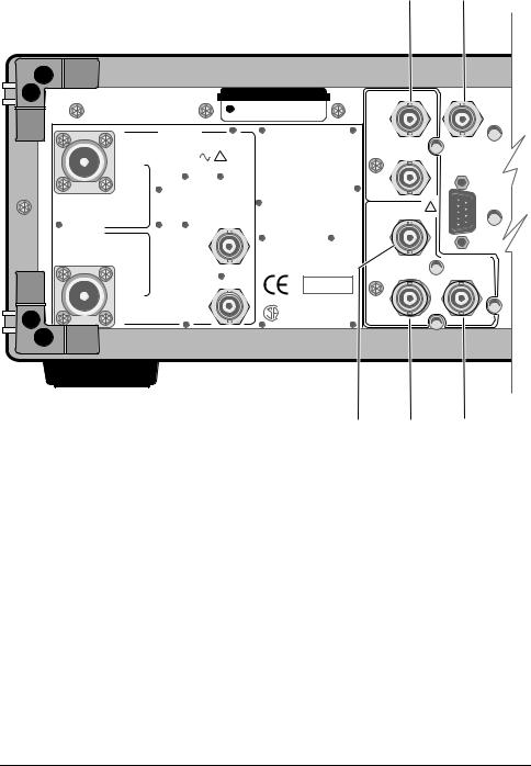
5071A Rear Panel Connections
(See Table 1-1 in this chapter for connector descriptions)
1 2
SERIAL PLATE |
OPTIONS |
8 kHz Sync In |
|
Status |
|
12.75 x 32 |
001 Hi Performance |
Output |
|
|
OUTPUTS |
|
TTL |
|
|
5071A |
50Ω |
|
|
|
+13 dBm 50 Ω |
8 kHz Sync Out |
|
|
Port |
Sine Wave |
! |
|
RS - 232C |
|
|
|
||
1 |
|
|
|
(DTE) |
|
WARNING: |
|
|
|
|
|
TTL |
|
|
|
|
To avold electric shock, |
|
|
|
|
50Ω |
|
|
|
|
do not remove covers. |
|
|
|
|
No user-serviceable parts |
Framed Output |
! |
|
|
inside. |
||
Programmable |
|
G.703/6 |
|
|
|
Refer all servicing to |
|
||
outputs |
|
qualified personnel. |
G.704 |
|
5MHz or |
|
|
50Ω |
|
10MHz |
1 MHz |
|
|
|
|
CAUTION: |
|
|
|
|
|
|
2.048 Mb/s |
|
|
|
METRIC & INCH HARDWARE |
|
|
|
|
CONSULT SERVICE MANUAL |
Sync Out |
Sync Out |
|
|
|
||
|
|
ISM 1-A |
|
|
Port |
|
92 |
|
|
|
|
|
|
|
2 |
100 kHz |
FOR LABORATORY USE BY |
75Ω |
50Ω |
QUALIFIED PERSONNEL |
||||
|
|
FOUR USAGE EN LABORATOIRE |
||
|
|
PAR PERSONNEL QUALIFIE |
||
|
|
|
G.703/10 |
TTL |
3 4 5
NOTE
The illustration on these pages depicts an 5071A equipped with Telecomm Options 048 and 272. When the telecomm output option includes either 100 or 120 Ω balanced output lines, the Framed Output connector will be a two-center-conductor BNC in place of the one shown above. In addition, the Mb/s and impedance designations will correspond to the particular telecomm output option shipped with the 5071A.
1-4

Operating and Programming
Getting Started
9
48 VDC Input |
POWER/FUSE 100VA MAX |
|
|
|
Line: |
1 |
00/120 |
V |
|
|
|
220/240 |
V |
|
Fuse: 2.5A |
250V |
Fuse: |
1.5 |
AT |
|
|
|
|
0.8 |
|
AT |
|
|
|
|
|
|
|
|||||
|
|
Freq: |
5 |
0-400 |
Hz |
|
5 |
|
0-60 |
Hz |
|
FUSE |
|
CAUTION: |
|
|
|
|
|
|
|
120 Vac |
|
|
|
|
|
|
|
|
|
|
|||
|
|
For continued protection against |
fire, |
replace |
|
||||||
|
|
only with |
fuse |
of s ame |
type |
and |
ratings. |
! |
|
|
|
Operating Voltage Range: |
40 to 5 8 VDC |
||
Input 1 |
GND |
Input 2 |
|
48 VDC |
48 VDC |
||
|
|||
TELECOM |
48Volt |
1.544 Mb/s |
2.048 Mb/s |
|
|
OPTIONS: |
048 |
104 |
220 |
221 |
222 |
|
|
105 |
270 |
271 |
272 |
7
1-5
 Loading...