


 Loading...
User’s Guide
Agilent Technologies
E8257D/67D PSG Signal Generators
This guide applies to the following signal generator models:
E8257D PSG Analog Signal Generator
E8267D PSG Vector Signal Generator
Due to our continuing efforts to improve our products through firmware and hardware revisions, signal generator design and operation may vary from descriptions in this guide. We recommend that you use the latest revision of this guide to ensure you have up-to-date product information. Compare the print date of this guide (see bottom of page) with the latest revision, which can be downloaded from the following website:
http://www.agilent.com/find/psg
Manufacturing Part Number: E825190353
Printed in USA
February 2008
© Copyright 20042008 Agilent Technologies, Inc.

Notice
The material in this document is provided “as is,” and is subject to change without notice in future editions.
Further, to the maximum extent permitted by applicable law, Agilent disclaims all warranties, either express or implied with regard to this manual and to any of the Agilent products to which it pertains, including but not limited to the implied warranties of merchantability and fitness for a particular purpose. Agilent shall not be liable for errors or for incidental or consequential damages in connection with the furnishing, use, or performance of this document or any of the Agilent products to which it pertains. Should Agilent have a written contract with the User and should any of the contract terms conflict with these terms, the contract terms shall control.
ii

Contents
1. Signal Generator Overview . . . . . . . . . . . . . . . . . . . . . . . . . . . . . . . . . . . . . . . . . . . . . . . . . . . . . . . 1
Signal Generator Models and Features. . . . . . . . . . . . . . . . . . . . . . . . . . . . . . . . . . . . . . . . . . . . . . . . .1
E8257D PSG Analog Signal Generator Features . . . . . . . . . . . . . . . . . . . . . . . . . . . . . . . . . . . . . . .2
E8267D PSG Vector Signal Generator Features . . . . . . . . . . . . . . . . . . . . . . . . . . . . . . . . . . . . . . . .3
Options . . . . . . . . . . . . . . . . . . . . . . . . . . . . . . . . . . . . . . . . . . . . . . . . . . . . . . . . . . . . . . . . . . . . . . . . .4
Firmware Upgrades. . . . . . . . . . . . . . . . . . . . . . . . . . . . . . . . . . . . . . . . . . . . . . . . . . . . . . . . . . . . . . . .4
To Upgrade Firmware . . . . . . . . . . . . . . . . . . . . . . . . . . . . . . . . . . . . . . . . . . . . . . . . . . . . . . . . . . . .4
Modes of Operation . . . . . . . . . . . . . . . . . . . . . . . . . . . . . . . . . . . . . . . . . . . . . . . . . . . . . . . . . . . . . . .5
Continuous Wave . . . . . . . . . . . . . . . . . . . . . . . . . . . . . . . . . . . . . . . . . . . . . . . . . . . . . . . . . . . . . . .5
Swept Signal . . . . . . . . . . . . . . . . . . . . . . . . . . . . . . . . . . . . . . . . . . . . . . . . . . . . . . . . . . . . . . . . . . .5
Analog Modulation . . . . . . . . . . . . . . . . . . . . . . . . . . . . . . . . . . . . . . . . . . . . . . . . . . . . . . . . . . . . . .5
Digital Modulation . . . . . . . . . . . . . . . . . . . . . . . . . . . . . . . . . . . . . . . . . . . . . . . . . . . . . . . . . . . . . .6
Front Panel . . . . . . . . . . . . . . . . . . . . . . . . . . . . . . . . . . . . . . . . . . . . . . . . . . . . . . . . . . . . . . . . . . . . . .7
1. Display . . . . . . . . . . . . . . . . . . . . . . . . . . . . . . . . . . . . . . . . . . . . . . . . . . . . . . . . . . . . . . . . . . . . .8
2. Softkeys. . . . . . . . . . . . . . . . . . . . . . . . . . . . . . . . . . . . . . . . . . . . . . . . . . . . . . . . . . . . . . . . . . . . .8
3. Knob . . . . . . . . . . . . . . . . . . . . . . . . . . . . . . . . . . . . . . . . . . . . . . . . . . . . . . . . . . . . . . . . . . . . . . .8
4. Amplitude . . . . . . . . . . . . . . . . . . . . . . . . . . . . . . . . . . . . . . . . . . . . . . . . . . . . . . . . . . . . . . . . . . .8
5. Frequency . . . . . . . . . . . . . . . . . . . . . . . . . . . . . . . . . . . . . . . . . . . . . . . . . . . . . . . . . . . . . . . . . . .8
6. Save . . . . . . . . . . . . . . . . . . . . . . . . . . . . . . . . . . . . . . . . . . . . . . . . . . . . . . . . . . . . . . . . . . . . . . . .8
7. Recall. . . . . . . . . . . . . . . . . . . . . . . . . . . . . . . . . . . . . . . . . . . . . . . . . . . . . . . . . . . . . . . . . . . . . . .8
8. Trigger . . . . . . . . . . . . . . . . . . . . . . . . . . . . . . . . . . . . . . . . . . . . . . . . . . . . . . . . . . . . . . . . . . . . . .9
9. MENUS. . . . . . . . . . . . . . . . . . . . . . . . . . . . . . . . . . . . . . . . . . . . . . . . . . . . . . . . . . . . . . . . . . . . .9
10. Help . . . . . . . . . . . . . . . . . . . . . . . . . . . . . . . . . . . . . . . . . . . . . . . . . . . . . . . . . . . . . . . . . . . . . . .9
11. EXT 1 INPUT . . . . . . . . . . . . . . . . . . . . . . . . . . . . . . . . . . . . . . . . . . . . . . . . . . . . . . . . . . . . . . .9
12. EXT 2 INPUT . . . . . . . . . . . . . . . . . . . . . . . . . . . . . . . . . . . . . . . . . . . . . . . . . . . . . . . . . . . . . .10
13. LF OUTPUT . . . . . . . . . . . . . . . . . . . . . . . . . . . . . . . . . . . . . . . . . . . . . . . . . . . . . . . . . . . . . . .10
14. Mod On/Off. . . . . . . . . . . . . . . . . . . . . . . . . . . . . . . . . . . . . . . . . . . . . . . . . . . . . . . . . . . . . . . .10
15. ALC INPUT . . . . . . . . . . . . . . . . . . . . . . . . . . . . . . . . . . . . . . . . . . . . . . . . . . . . . . . . . . . . . . .10
16. RF On/Off . . . . . . . . . . . . . . . . . . . . . . . . . . . . . . . . . . . . . . . . . . . . . . . . . . . . . . . . . . . . . . . . .10
17. Numeric Keypad . . . . . . . . . . . . . . . . . . . . . . . . . . . . . . . . . . . . . . . . . . . . . . . . . . . . . . . . . . . .10
18. RF OUTPUT . . . . . . . . . . . . . . . . . . . . . . . . . . . . . . . . . . . . . . . . . . . . . . . . . . . . . . . . . . . . . . . 11
19. SYNC OUT. . . . . . . . . . . . . . . . . . . . . . . . . . . . . . . . . . . . . . . . . . . . . . . . . . . . . . . . . . . . . . . . 11
20. VIDEO OUT . . . . . . . . . . . . . . . . . . . . . . . . . . . . . . . . . . . . . . . . . . . . . . . . . . . . . . . . . . . . . . . 11
21. Incr Set . . . . . . . . . . . . . . . . . . . . . . . . . . . . . . . . . . . . . . . . . . . . . . . . . . . . . . . . . . . . . . . . . . . 11
22. GATE/ PULSE/ TRIGGER INPUT . . . . . . . . . . . . . . . . . . . . . . . . . . . . . . . . . . . . . . . . . . . . . 11
23. Arrow Keys . . . . . . . . . . . . . . . . . . . . . . . . . . . . . . . . . . . . . . . . . . . . . . . . . . . . . . . . . . . . . . . . 11
24. Hold. . . . . . . . . . . . . . . . . . . . . . . . . . . . . . . . . . . . . . . . . . . . . . . . . . . . . . . . . . . . . . . . . . . . . . 11
25. Return . . . . . . . . . . . . . . . . . . . . . . . . . . . . . . . . . . . . . . . . . . . . . . . . . . . . . . . . . . . . . . . . . . . .12
iii

Contents
26. Contrast Decrease . . . . . . . . . . . . . . . . . . . . . . . . . . . . . . . . . . . . . . . . . . . . . . . . . . . . . . . . . . . 12
27. Contrast Increase. . . . . . . . . . . . . . . . . . . . . . . . . . . . . . . . . . . . . . . . . . . . . . . . . . . . . . . . . . . . 12
28. Local . . . . . . . . . . . . . . . . . . . . . . . . . . . . . . . . . . . . . . . . . . . . . . . . . . . . . . . . . . . . . . . . . . . . . 12
29. Preset. . . . . . . . . . . . . . . . . . . . . . . . . . . . . . . . . . . . . . . . . . . . . . . . . . . . . . . . . . . . . . . . . . . . . 12
30. Line Power LED . . . . . . . . . . . . . . . . . . . . . . . . . . . . . . . . . . . . . . . . . . . . . . . . . . . . . . . . . . . . 12
31. LINE . . . . . . . . . . . . . . . . . . . . . . . . . . . . . . . . . . . . . . . . . . . . . . . . . . . . . . . . . . . . . . . . . . . . . 12
32. Standby LED. . . . . . . . . . . . . . . . . . . . . . . . . . . . . . . . . . . . . . . . . . . . . . . . . . . . . . . . . . . . . . . 12
33. SYMBOL SYNC . . . . . . . . . . . . . . . . . . . . . . . . . . . . . . . . . . . . . . . . . . . . . . . . . . . . . . . . . . . 12
34. DATA CLOCK . . . . . . . . . . . . . . . . . . . . . . . . . . . . . . . . . . . . . . . . . . . . . . . . . . . . . . . . . . . . . 13
35. DATA . . . . . . . . . . . . . . . . . . . . . . . . . . . . . . . . . . . . . . . . . . . . . . . . . . . . . . . . . . . . . . . . . . . . 13
36. Q Input . . . . . . . . . . . . . . . . . . . . . . . . . . . . . . . . . . . . . . . . . . . . . . . . . . . . . . . . . . . . . . . . . . . 13
37. I Input . . . . . . . . . . . . . . . . . . . . . . . . . . . . . . . . . . . . . . . . . . . . . . . . . . . . . . . . . . . . . . . . . . . . 13
Front Panel Display . . . . . . . . . . . . . . . . . . . . . . . . . . . . . . . . . . . . . . . . . . . . . . . . . . . . . . . . . . . . . . 14
1. Active Entry Area . . . . . . . . . . . . . . . . . . . . . . . . . . . . . . . . . . . . . . . . . . . . . . . . . . . . . . . . . . . . 15
2. Frequency Area. . . . . . . . . . . . . . . . . . . . . . . . . . . . . . . . . . . . . . . . . . . . . . . . . . . . . . . . . . . . . . 15
3. Annunciators. . . . . . . . . . . . . . . . . . . . . . . . . . . . . . . . . . . . . . . . . . . . . . . . . . . . . . . . . . . . . . . . 15
4. Digital Modulation Annunciators . . . . . . . . . . . . . . . . . . . . . . . . . . . . . . . . . . . . . . . . . . . . . . . . 17
5. Amplitude Area. . . . . . . . . . . . . . . . . . . . . . . . . . . . . . . . . . . . . . . . . . . . . . . . . . . . . . . . . . . . . . 17
6. Error Message Area . . . . . . . . . . . . . . . . . . . . . . . . . . . . . . . . . . . . . . . . . . . . . . . . . . . . . . . . . . 17
7. Text Area. . . . . . . . . . . . . . . . . . . . . . . . . . . . . . . . . . . . . . . . . . . . . . . . . . . . . . . . . . . . . . . . . . . 17
8. Softkey Label Area . . . . . . . . . . . . . . . . . . . . . . . . . . . . . . . . . . . . . . . . . . . . . . . . . . . . . . . . . . . 17
Rear Panel. . . . . . . . . . . . . . . . . . . . . . . . . . . . . . . . . . . . . . . . . . . . . . . . . . . . . . . . . . . . . . . . . . . . . . 18 1. EVENT 1 . . . . . . . . . . . . . . . . . . . . . . . . . . . . . . . . . . . . . . . . . . . . . . . . . . . . . . . . . . . . . . . . . . 22 2. EVENT 2 . . . . . . . . . . . . . . . . . . . . . . . . . . . . . . . . . . . . . . . . . . . . . . . . . . . . . . . . . . . . . . . . . . 22 3. PATTERN TRIG IN . . . . . . . . . . . . . . . . . . . . . . . . . . . . . . . . . . . . . . . . . . . . . . . . . . . . . . . . . . 22 4. BURST GATE IN . . . . . . . . . . . . . . . . . . . . . . . . . . . . . . . . . . . . . . . . . . . . . . . . . . . . . . . . . . . . 22 5. AUXILIARY I/O . . . . . . . . . . . . . . . . . . . . . . . . . . . . . . . . . . . . . . . . . . . . . . . . . . . . . . . . . . . . 23 6. DIGITAL BUS . . . . . . . . . . . . . . . . . . . . . . . . . . . . . . . . . . . . . . . . . . . . . . . . . . . . . . . . . . . . . . 24 7. Q OUT . . . . . . . . . . . . . . . . . . . . . . . . . . . . . . . . . . . . . . . . . . . . . . . . . . . . . . . . . . . . . . . . . . . . 24 8. I OUT . . . . . . . . . . . . . . . . . . . . . . . . . . . . . . . . . . . . . . . . . . . . . . . . . . . . . . . . . . . . . . . . . . . . . 24 9. WIDEBAND I INPUTS . . . . . . . . . . . . . . . . . . . . . . . . . . . . . . . . . . . . . . . . . . . . . . . . . . . . . . . 24 10. I-bar OUT . . . . . . . . . . . . . . . . . . . . . . . . . . . . . . . . . . . . . . . . . . . . . . . . . . . . . . . . . . . . . . . . . 25 11. WIDEBAND Q INPUTS . . . . . . . . . . . . . . . . . . . . . . . . . . . . . . . . . . . . . . . . . . . . . . . . . . . . . 25 12. COH CARRIER . . . . . . . . . . . . . . . . . . . . . . . . . . . . . . . . . . . . . . . . . . . . . . . . . . . . . . . . . . . . 25 13. 1 GHz REF OUT (Serial Prefixes >=US4646/MY4646) . . . . . . . . . . . . . . . . . . . . . . . . . . . . . 25 14. Q-bar OUT . . . . . . . . . . . . . . . . . . . . . . . . . . . . . . . . . . . . . . . . . . . . . . . . . . . . . . . . . . . . . . . . 26 15. AC Power Receptacle . . . . . . . . . . . . . . . . . . . . . . . . . . . . . . . . . . . . . . . . . . . . . . . . . . . . . . . . 26 16. GPIB . . . . . . . . . . . . . . . . . . . . . . . . . . . . . . . . . . . . . . . . . . . . . . . . . . . . . . . . . . . . . . . . . . . . . 26
iv

Contents
17. 10 MHz EFC . . . . . . . . . . . . . . . . . . . . . . . . . . . . . . . . . . . . . . . . . . . . . . . . . . . . . . . . . . . . . . .26 18. ALC HOLD (Serial Prefixes >=US4722/MY4722) . . . . . . . . . . . . . . . . . . . . . . . . . . . . . . . . .26 19. AUXILIARY INTERFACE . . . . . . . . . . . . . . . . . . . . . . . . . . . . . . . . . . . . . . . . . . . . . . . . . . .27 20. 10 MHz IN . . . . . . . . . . . . . . . . . . . . . . . . . . . . . . . . . . . . . . . . . . . . . . . . . . . . . . . . . . . . . . . .27 21. LAN. . . . . . . . . . . . . . . . . . . . . . . . . . . . . . . . . . . . . . . . . . . . . . . . . . . . . . . . . . . . . . . . . . . . . .27 22. 10 MHz OUT . . . . . . . . . . . . . . . . . . . . . . . . . . . . . . . . . . . . . . . . . . . . . . . . . . . . . . . . . . . . . .28 23. STOP SWEEP IN/OUT. . . . . . . . . . . . . . . . . . . . . . . . . . . . . . . . . . . . . . . . . . . . . . . . . . . . . . .28 24. BASEBAND GEN CLK IN . . . . . . . . . . . . . . . . . . . . . . . . . . . . . . . . . . . . . . . . . . . . . . . . . . .28 25. Z-AXIS BLANK/MKRS. . . . . . . . . . . . . . . . . . . . . . . . . . . . . . . . . . . . . . . . . . . . . . . . . . . . . .28 26. SWEEP OUT. . . . . . . . . . . . . . . . . . . . . . . . . . . . . . . . . . . . . . . . . . . . . . . . . . . . . . . . . . . . . . .28 27. TRIGGER OUT . . . . . . . . . . . . . . . . . . . . . . . . . . . . . . . . . . . . . . . . . . . . . . . . . . . . . . . . . . . .29 28. TRIGGER IN . . . . . . . . . . . . . . . . . . . . . . . . . . . . . . . . . . . . . . . . . . . . . . . . . . . . . . . . . . . . . .29 29. SOURCE SETTLED. . . . . . . . . . . . . . . . . . . . . . . . . . . . . . . . . . . . . . . . . . . . . . . . . . . . . . . . .29 30. SOURCE MODULE INTERFACE . . . . . . . . . . . . . . . . . . . . . . . . . . . . . . . . . . . . . . . . . . . . .29 31. RF OUT. . . . . . . . . . . . . . . . . . . . . . . . . . . . . . . . . . . . . . . . . . . . . . . . . . . . . . . . . . . . . . . . . . .29 32. EXT 1 . . . . . . . . . . . . . . . . . . . . . . . . . . . . . . . . . . . . . . . . . . . . . . . . . . . . . . . . . . . . . . . . . . . .29 33. EXT 2 . . . . . . . . . . . . . . . . . . . . . . . . . . . . . . . . . . . . . . . . . . . . . . . . . . . . . . . . . . . . . . . . . . . .30 34. PULSE SYNC OUT . . . . . . . . . . . . . . . . . . . . . . . . . . . . . . . . . . . . . . . . . . . . . . . . . . . . . . . . .30 35. PULSE VIDEO OUT . . . . . . . . . . . . . . . . . . . . . . . . . . . . . . . . . . . . . . . . . . . . . . . . . . . . . . . .30 36. PULSE/TRIG GATE INPUT . . . . . . . . . . . . . . . . . . . . . . . . . . . . . . . . . . . . . . . . . . . . . . . . . .30 37. ALC INPUT . . . . . . . . . . . . . . . . . . . . . . . . . . . . . . . . . . . . . . . . . . . . . . . . . . . . . . . . . . . . . . .30 38. DATA CLOCK . . . . . . . . . . . . . . . . . . . . . . . . . . . . . . . . . . . . . . . . . . . . . . . . . . . . . . . . . . . . .30 39. I IN . . . . . . . . . . . . . . . . . . . . . . . . . . . . . . . . . . . . . . . . . . . . . . . . . . . . . . . . . . . . . . . . . . . . . .31 40. SYMBOL SYNC. . . . . . . . . . . . . . . . . . . . . . . . . . . . . . . . . . . . . . . . . . . . . . . . . . . . . . . . . . . .31 41. Q IN. . . . . . . . . . . . . . . . . . . . . . . . . . . . . . . . . . . . . . . . . . . . . . . . . . . . . . . . . . . . . . . . . . . . . .31 42. DATA. . . . . . . . . . . . . . . . . . . . . . . . . . . . . . . . . . . . . . . . . . . . . . . . . . . . . . . . . . . . . . . . . . . . .31 43. LF OUT. . . . . . . . . . . . . . . . . . . . . . . . . . . . . . . . . . . . . . . . . . . . . . . . . . . . . . . . . . . . . . . . . . .32
2. Basic Operation. . . . . . . . . . . . . . . . . . . . . . . . . . . . . . . . . . . . . . . . . . . . . . . . . . . . . . . . . . . . . . . . .33
Using Table Editors. . . . . . . . . . . . . . . . . . . . . . . . . . . . . . . . . . . . . . . . . . . . . . . . . . . . . . . . . . . . . . .34
Table Editor Softkeys . . . . . . . . . . . . . . . . . . . . . . . . . . . . . . . . . . . . . . . . . . . . . . . . . . . . . . . . . . .35
Modifying Table Items in the Data Fields. . . . . . . . . . . . . . . . . . . . . . . . . . . . . . . . . . . . . . . . . . . .35
Configuring the RF Output . . . . . . . . . . . . . . . . . . . . . . . . . . . . . . . . . . . . . . . . . . . . . . . . . . . . . . . . .36
Configuring a Continuous Wave RF Output . . . . . . . . . . . . . . . . . . . . . . . . . . . . . . . . . . . . . . . . . .36
Configuring a Swept RF Output . . . . . . . . . . . . . . . . . . . . . . . . . . . . . . . . . . . . . . . . . . . . . . . . . . .38
Extending the Frequency Range . . . . . . . . . . . . . . . . . . . . . . . . . . . . . . . . . . . . . . . . . . . . . . . . . . .53
Modulating a Signal . . . . . . . . . . . . . . . . . . . . . . . . . . . . . . . . . . . . . . . . . . . . . . . . . . . . . . . . . . . . . .53
Turning On a Modulation Format . . . . . . . . . . . . . . . . . . . . . . . . . . . . . . . . . . . . . . . . . . . . . . . . . .53
v

Contents
Applying a Modulation Format to the RF Output . . . . . . . . . . . . . . . . . . . . . . . . . . . . . . . . . . . . . 54 Using Data Storage Functions . . . . . . . . . . . . . . . . . . . . . . . . . . . . . . . . . . . . . . . . . . . . . . . . . . . . . . 55 Using the Memory Catalog. . . . . . . . . . . . . . . . . . . . . . . . . . . . . . . . . . . . . . . . . . . . . . . . . . . . . . . 55 Using the Instrument State Registers . . . . . . . . . . . . . . . . . . . . . . . . . . . . . . . . . . . . . . . . . . . . . . . 57 Using Security Functions . . . . . . . . . . . . . . . . . . . . . . . . . . . . . . . . . . . . . . . . . . . . . . . . . . . . . . . . . . 59 Understanding PSG Memory Types . . . . . . . . . . . . . . . . . . . . . . . . . . . . . . . . . . . . . . . . . . . . . . . . 60 Removing Sensitive Data from PSG Memory . . . . . . . . . . . . . . . . . . . . . . . . . . . . . . . . . . . . . . . . 63 Using the Secure Display . . . . . . . . . . . . . . . . . . . . . . . . . . . . . . . . . . . . . . . . . . . . . . . . . . . . . . . . 66 Enabling Options . . . . . . . . . . . . . . . . . . . . . . . . . . . . . . . . . . . . . . . . . . . . . . . . . . . . . . . . . . . . . . . . 66 Enabling a Software Option . . . . . . . . . . . . . . . . . . . . . . . . . . . . . . . . . . . . . . . . . . . . . . . . . . . . . . 66 Using the Web Server . . . . . . . . . . . . . . . . . . . . . . . . . . . . . . . . . . . . . . . . . . . . . . . . . . . . . . . . . . . . . 67 Activating the Web Server . . . . . . . . . . . . . . . . . . . . . . . . . . . . . . . . . . . . . . . . . . . . . . . . . . . . . . . 68
3. Basic Digital Operation . . . . . . . . . . . . . . . . . . . . . . . . . . . . . . . . . . . . . . . . . . . . . . . . . . . . . . . . . . 71
Custom Modulation . . . . . . . . . . . . . . . . . . . . . . . . . . . . . . . . . . . . . . . . . . . . . . . . . . . . . . . . . . . . . . 71 Custom Arb Waveform Generator . . . . . . . . . . . . . . . . . . . . . . . . . . . . . . . . . . . . . . . . . . . . . . . . . 72 Custom Real Time I/Q Baseband . . . . . . . . . . . . . . . . . . . . . . . . . . . . . . . . . . . . . . . . . . . . . . . . . . 72 Arbitrary (ARB) Waveform File Headers . . . . . . . . . . . . . . . . . . . . . . . . . . . . . . . . . . . . . . . . . . . . . 72 Creating a File Header for a Modulation Format Waveform . . . . . . . . . . . . . . . . . . . . . . . . . . . . . 73 Modifying Header Information in a Modulation Format . . . . . . . . . . . . . . . . . . . . . . . . . . . . . . . . 74 Storing Header Information for a Dual ARB Player Waveform Sequence . . . . . . . . . . . . . . . . . . 79 Modifying and Viewing Header Information in the Dual ARB Player . . . . . . . . . . . . . . . . . . . . . 79 Playing a Waveform File that Contains a Header. . . . . . . . . . . . . . . . . . . . . . . . . . . . . . . . . . . . . . 82 Using the Dual ARB Waveform Player . . . . . . . . . . . . . . . . . . . . . . . . . . . . . . . . . . . . . . . . . . . . . . . 83 Accessing the Dual ARB Player. . . . . . . . . . . . . . . . . . . . . . . . . . . . . . . . . . . . . . . . . . . . . . . . . . . 83 Creating Waveform Segments . . . . . . . . . . . . . . . . . . . . . . . . . . . . . . . . . . . . . . . . . . . . . . . . . . . . 84 Building and Storing a Waveform Sequence . . . . . . . . . . . . . . . . . . . . . . . . . . . . . . . . . . . . . . . . . 85 Playing a Waveform . . . . . . . . . . . . . . . . . . . . . . . . . . . . . . . . . . . . . . . . . . . . . . . . . . . . . . . . . . . . 86 Editing a Waveform Sequence . . . . . . . . . . . . . . . . . . . . . . . . . . . . . . . . . . . . . . . . . . . . . . . . . . . . 86 Adding Real-Time Noise to a Dual ARB Waveform . . . . . . . . . . . . . . . . . . . . . . . . . . . . . . . . . . . 86 Storing and Loading Waveform Segments . . . . . . . . . . . . . . . . . . . . . . . . . . . . . . . . . . . . . . . . . . . 87 Renaming a Waveform Segment . . . . . . . . . . . . . . . . . . . . . . . . . . . . . . . . . . . . . . . . . . . . . . . . . . 88 Using Waveform Markers . . . . . . . . . . . . . . . . . . . . . . . . . . . . . . . . . . . . . . . . . . . . . . . . . . . . . . . . . 88 Waveform Marker Concepts . . . . . . . . . . . . . . . . . . . . . . . . . . . . . . . . . . . . . . . . . . . . . . . . . . . . . . 89 Accessing Marker Utilities . . . . . . . . . . . . . . . . . . . . . . . . . . . . . . . . . . . . . . . . . . . . . . . . . . . . . . . 92 Viewing Waveform Segment Markers . . . . . . . . . . . . . . . . . . . . . . . . . . . . . . . . . . . . . . . . . . . . . . 93 1. Clearing Marker Points from a Waveform Segment . . . . . . . . . . . . . . . . . . . . . . . . . . . . . . . . . 94 2. Setting Marker Points in a Waveform Segment. . . . . . . . . . . . . . . . . . . . . . . . . . . . . . . . . . . . . 95
vi

Contents
3. Controlling Markers in a Waveform Sequence (Dual ARB Only) . . . . . . . . . . . . . . . . . . . . . .97
Viewing a Marker Pulse . . . . . . . . . . . . . . . . . . . . . . . . . . . . . . . . . . . . . . . . . . . . . . . . . . . . . . . . .99
Using the RF Blanking Marker Function . . . . . . . . . . . . . . . . . . . . . . . . . . . . . . . . . . . . . . . . . . .100
Setting Marker Polarity . . . . . . . . . . . . . . . . . . . . . . . . . . . . . . . . . . . . . . . . . . . . . . . . . . . . . . . . .102
Triggering Waveforms . . . . . . . . . . . . . . . . . . . . . . . . . . . . . . . . . . . . . . . . . . . . . . . . . . . . . . . . . . .102
Source . . . . . . . . . . . . . . . . . . . . . . . . . . . . . . . . . . . . . . . . . . . . . . . . . . . . . . . . . . . . . . . . . . . . . .103
Mode and Response . . . . . . . . . . . . . . . . . . . . . . . . . . . . . . . . . . . . . . . . . . . . . . . . . . . . . . . . . . .103
Accessing Trigger Utilities . . . . . . . . . . . . . . . . . . . . . . . . . . . . . . . . . . . . . . . . . . . . . . . . . . . . . .104
Setting the Polarity of an External Trigger . . . . . . . . . . . . . . . . . . . . . . . . . . . . . . . . . . . . . . . . . .105
Using Gated Triggering. . . . . . . . . . . . . . . . . . . . . . . . . . . . . . . . . . . . . . . . . . . . . . . . . . . . . . . . .105
Using Segment Advance Triggering . . . . . . . . . . . . . . . . . . . . . . . . . . . . . . . . . . . . . . . . . . . . . . .107
Using Waveform Clipping . . . . . . . . . . . . . . . . . . . . . . . . . . . . . . . . . . . . . . . . . . . . . . . . . . . . . . . .108
How Power Peaks Develop . . . . . . . . . . . . . . . . . . . . . . . . . . . . . . . . . . . . . . . . . . . . . . . . . . . . . .108
How Peaks Cause Spectral Regrowth . . . . . . . . . . . . . . . . . . . . . . . . . . . . . . . . . . . . . . . . . . . . . .110
How Clipping Reduces Peak-to-Average Power. . . . . . . . . . . . . . . . . . . . . . . . . . . . . . . . . . . . . . 111
Configuring Circular Clipping . . . . . . . . . . . . . . . . . . . . . . . . . . . . . . . . . . . . . . . . . . . . . . . . . . .114
Configuring Rectangular Clipping . . . . . . . . . . . . . . . . . . . . . . . . . . . . . . . . . . . . . . . . . . . . . . . .115
Using Waveform Scaling . . . . . . . . . . . . . . . . . . . . . . . . . . . . . . . . . . . . . . . . . . . . . . . . . . . . . . . . .116
How DAC Over-Range Errors Occur . . . . . . . . . . . . . . . . . . . . . . . . . . . . . . . . . . . . . . . . . . . . . .116
How Scaling Eliminates DAC Over-Range Errors . . . . . . . . . . . . . . . . . . . . . . . . . . . . . . . . . . . .117
Scaling a Currently Playing Waveform (Runtime Scaling) . . . . . . . . . . . . . . . . . . . . . . . . . . . . .118
Scaling a Waveform File in Volatile Memory. . . . . . . . . . . . . . . . . . . . . . . . . . . . . . . . . . . . . . . .118
4. Optimizing Performance . . . . . . . . . . . . . . . . . . . . . . . . . . . . . . . . . . . . . . . . . . . . . . . . . . . . . . . . .119
Using the ALC . . . . . . . . . . . . . . . . . . . . . . . . . . . . . . . . . . . . . . . . . . . . . . . . . . . . . . . . . . . . . . . . .119 Selecting ALC Bandwidth . . . . . . . . . . . . . . . . . . . . . . . . . . . . . . . . . . . . . . . . . . . . . . . . . . . . . .119 To Select an ALC Bandwidth . . . . . . . . . . . . . . . . . . . . . . . . . . . . . . . . . . . . . . . . . . . . . . . . . . . .119 Using External Leveling . . . . . . . . . . . . . . . . . . . . . . . . . . . . . . . . . . . . . . . . . . . . . . . . . . . . . . . . . .120 To Level with Detectors and Couplers/Splitters . . . . . . . . . . . . . . . . . . . . . . . . . . . . . . . . . . . . . .120 To Level with a mm-Wave Source Module. . . . . . . . . . . . . . . . . . . . . . . . . . . . . . . . . . . . . . . . . .123 Creating and Applying User Flatness Correction . . . . . . . . . . . . . . . . . . . . . . . . . . . . . . . . . . . . . . .123 Creating a User Flatness Correction Array . . . . . . . . . . . . . . . . . . . . . . . . . . . . . . . . . . . . . . . . . .124 Creating a User Flatness Correction Array with a mm-Wave Source Module . . . . . . . . . . . . . . .128 Adjusting Reference Oscillator Bandwidth (Option UNR/UNX) . . . . . . . . . . . . . . . . . . . . . . . . . .134 To Select the Reference Oscillator Bandwidth. . . . . . . . . . . . . . . . . . . . . . . . . . . . . . . . . . . . . . .134 To Restore Factory Default Settings: . . . . . . . . . . . . . . . . . . . . . . . . . . . . . . . . . . . . . . . . . . . . . .135
5. Analog Modulation . . . . . . . . . . . . . . . . . . . . . . . . . . . . . . . . . . . . . . . . . . . . . . . . . . . . . . . . . . . . .137
vii

Contents
Analog Modulation Waveforms . . . . . . . . . . . . . . . . . . . . . . . . . . . . . . . . . . . . . . . . . . . . . . . . . . . . 137 Configuring AM (Option UNT) . . . . . . . . . . . . . . . . . . . . . . . . . . . . . . . . . . . . . . . . . . . . . . . . . . . . 138 To Set the Carrier Frequency . . . . . . . . . . . . . . . . . . . . . . . . . . . . . . . . . . . . . . . . . . . . . . . . . . . . 138 To Set the RF Output Amplitude . . . . . . . . . . . . . . . . . . . . . . . . . . . . . . . . . . . . . . . . . . . . . . . . . 138 To Set the AM Depth and Rate. . . . . . . . . . . . . . . . . . . . . . . . . . . . . . . . . . . . . . . . . . . . . . . . . . . 138 To Turn on Amplitude Modulation. . . . . . . . . . . . . . . . . . . . . . . . . . . . . . . . . . . . . . . . . . . . . . . . 138 Configuring FM (Option UNT) . . . . . . . . . . . . . . . . . . . . . . . . . . . . . . . . . . . . . . . . . . . . . . . . . . . . 138 To Set the RF Output Frequency . . . . . . . . . . . . . . . . . . . . . . . . . . . . . . . . . . . . . . . . . . . . . . . . . 138 To Set the RF Output Amplitude . . . . . . . . . . . . . . . . . . . . . . . . . . . . . . . . . . . . . . . . . . . . . . . . . 138 To Set the FM Deviation and Rate . . . . . . . . . . . . . . . . . . . . . . . . . . . . . . . . . . . . . . . . . . . . . . . . 139 To Activate FM . . . . . . . . . . . . . . . . . . . . . . . . . . . . . . . . . . . . . . . . . . . . . . . . . . . . . . . . . . . . . . . 139 Configuring ΦM (Option UNT). . . . . . . . . . . . . . . . . . . . . . . . . . . . . . . . . . . . . . . . . . . . . . . . . . . . 139 To Set the RF Output Frequency . . . . . . . . . . . . . . . . . . . . . . . . . . . . . . . . . . . . . . . . . . . . . . . . . 139 To Set the RF Output Amplitude . . . . . . . . . . . . . . . . . . . . . . . . . . . . . . . . . . . . . . . . . . . . . . . . . 139 To Set the FM Deviation and Rate . . . . . . . . . . . . . . . . . . . . . . . . . . . . . . . . . . . . . . . . . . . . . . . . 139 To Activate FM . . . . . . . . . . . . . . . . . . . . . . . . . . . . . . . . . . . . . . . . . . . . . . . . . . . . . . . . . . . . . . . 140 Configuring Pulse Modulation (Option UNU/UNW) . . . . . . . . . . . . . . . . . . . . . . . . . . . . . . . . . . . 140 To Set the RF Output Frequency . . . . . . . . . . . . . . . . . . . . . . . . . . . . . . . . . . . . . . . . . . . . . . . . . 140 To Set the RF Output Amplitude . . . . . . . . . . . . . . . . . . . . . . . . . . . . . . . . . . . . . . . . . . . . . . . . . 140 To Set the Pulse Period, Width, and Triggering . . . . . . . . . . . . . . . . . . . . . . . . . . . . . . . . . . . . . . 140 To Activate Pulse Modulation . . . . . . . . . . . . . . . . . . . . . . . . . . . . . . . . . . . . . . . . . . . . . . . . . . . 140 Configuring the LF Output (Option UNT). . . . . . . . . . . . . . . . . . . . . . . . . . . . . . . . . . . . . . . . . . . . 141 To Configure the LF Output with an Internal Modulation Source . . . . . . . . . . . . . . . . . . . . . . . . 141 To Configure the LF Output with a Function Generator Source . . . . . . . . . . . . . . . . . . . . . . . . . 142
6. Custom Arb Waveform Generator . . . . . . . . . . . . . . . . . . . . . . . . . . . . . . . . . . . . . . . . . . . . . . . . . 143
Overview . . . . . . . . . . . . . . . . . . . . . . . . . . . . . . . . . . . . . . . . . . . . . . . . . . . . . . . . . . . . . . . . . . . . . 143 Working with Predefined Setups (Modes) . . . . . . . . . . . . . . . . . . . . . . . . . . . . . . . . . . . . . . . . . . . . 143 Selecting a Custom ARB Setup or a Custom Digital Modulation State. . . . . . . . . . . . . . . . . . . . 144 Working with User-Defined Setups (Modes)-Custom Arb Only . . . . . . . . . . . . . . . . . . . . . . . . . . . 144 Modifying a Single-Carrier NADC Setup . . . . . . . . . . . . . . . . . . . . . . . . . . . . . . . . . . . . . . . . . . 144 Customizing a Multicarrier Setup. . . . . . . . . . . . . . . . . . . . . . . . . . . . . . . . . . . . . . . . . . . . . . . . . 145 Recalling a User-Defined Custom Digital Modulation State . . . . . . . . . . . . . . . . . . . . . . . . . . . . 146 Working with Filters. . . . . . . . . . . . . . . . . . . . . . . . . . . . . . . . . . . . . . . . . . . . . . . . . . . . . . . . . . . . . 146 Using a Predefined FIR Filter. . . . . . . . . . . . . . . . . . . . . . . . . . . . . . . . . . . . . . . . . . . . . . . . . . . . 147 Using a User-Defined FIR Filter. . . . . . . . . . . . . . . . . . . . . . . . . . . . . . . . . . . . . . . . . . . . . . . . . . 148 Working with Symbol Rates. . . . . . . . . . . . . . . . . . . . . . . . . . . . . . . . . . . . . . . . . . . . . . . . . . . . . . . 153 To Set a Symbol Rate . . . . . . . . . . . . . . . . . . . . . . . . . . . . . . . . . . . . . . . . . . . . . . . . . . . . . . . . . . 153
viii

Contents
To Restore the Default Symbol Rate (Custom Real Time I/Q Only) . . . . . . . . . . . . . . . . . . . . . .154 Working with Modulation Types . . . . . . . . . . . . . . . . . . . . . . . . . . . . . . . . . . . . . . . . . . . . . . . . . . .155 To Select a Predefined Modulation Type . . . . . . . . . . . . . . . . . . . . . . . . . . . . . . . . . . . . . . . . . . .155 To Use a User-Defined Modulation Type (Real Time I/Q Only) . . . . . . . . . . . . . . . . . . . . . . . . .156 Differential Wideband IQ (Option 016) . . . . . . . . . . . . . . . . . . . . . . . . . . . . . . . . . . . . . . . . . . . .161 Single-Ended Wideband IQ (Option 015 - Discontinued) . . . . . . . . . . . . . . . . . . . . . . . . . . . . . .161 Configuring Hardware . . . . . . . . . . . . . . . . . . . . . . . . . . . . . . . . . . . . . . . . . . . . . . . . . . . . . . . . . . .162 To Set a Delayed, Positive Polarity, External Single Trigger . . . . . . . . . . . . . . . . . . . . . . . . . . . .162 To Set the ARB Reference . . . . . . . . . . . . . . . . . . . . . . . . . . . . . . . . . . . . . . . . . . . . . . . . . . . . . .163
7. Custom Real Time I/Q Baseband. . . . . . . . . . . . . . . . . . . . . . . . . . . . . . . . . . . . . . . . . . . . . . . . . .165
Overview. . . . . . . . . . . . . . . . . . . . . . . . . . . . . . . . . . . . . . . . . . . . . . . . . . . . . . . . . . . . . . . . . . . . . .165 Working with Predefined Setups (Modes) . . . . . . . . . . . . . . . . . . . . . . . . . . . . . . . . . . . . . . . . . . . .165 Selecting a Predefined Real Time Modulation Setup . . . . . . . . . . . . . . . . . . . . . . . . . . . . . . . . . .165 Deselecting a Predefined Real Time Modulation Setup . . . . . . . . . . . . . . . . . . . . . . . . . . . . . . . .166 Working with Data Patterns . . . . . . . . . . . . . . . . . . . . . . . . . . . . . . . . . . . . . . . . . . . . . . . . . . . . . . .166 Using a Predefined Data Pattern . . . . . . . . . . . . . . . . . . . . . . . . . . . . . . . . . . . . . . . . . . . . . . . . . .167 Using a User-Defined Data Pattern . . . . . . . . . . . . . . . . . . . . . . . . . . . . . . . . . . . . . . . . . . . . . . . .167 Using an Externally Supplied Data Pattern. . . . . . . . . . . . . . . . . . . . . . . . . . . . . . . . . . . . . . . . . .171 Working with Burst Shapes . . . . . . . . . . . . . . . . . . . . . . . . . . . . . . . . . . . . . . . . . . . . . . . . . . . . . . .171 Configuring the Burst Rise and Fall Parameters. . . . . . . . . . . . . . . . . . . . . . . . . . . . . . . . . . . . . .172 Using User-Defined Burst Shape Curves . . . . . . . . . . . . . . . . . . . . . . . . . . . . . . . . . . . . . . . . . . .172 Configuring Hardware . . . . . . . . . . . . . . . . . . . . . . . . . . . . . . . . . . . . . . . . . . . . . . . . . . . . . . . . . . .175 To Set the BBG Reference . . . . . . . . . . . . . . . . . . . . . . . . . . . . . . . . . . . . . . . . . . . . . . . . . . . . . .175 To Set the External DATA CLOCK to Receive Input as Either Normal or Symbol. . . . . . . . . . .176 To Set the BBG DATA CLOCK to External or Internal . . . . . . . . . . . . . . . . . . . . . . . . . . . . . . . .176 To Adjust the I/Q Scaling . . . . . . . . . . . . . . . . . . . . . . . . . . . . . . . . . . . . . . . . . . . . . . . . . . . . . . .176 Working with Phase Polarity . . . . . . . . . . . . . . . . . . . . . . . . . . . . . . . . . . . . . . . . . . . . . . . . . . . . . .177 To Set Phase Polarity to Normal or Inverted. . . . . . . . . . . . . . . . . . . . . . . . . . . . . . . . . . . . . . . . .177 Working with Differential Data Encoding . . . . . . . . . . . . . . . . . . . . . . . . . . . . . . . . . . . . . . . . . . . .177 Understanding Differential Encoding . . . . . . . . . . . . . . . . . . . . . . . . . . . . . . . . . . . . . . . . . . . . . .177 Using Differential Encoding . . . . . . . . . . . . . . . . . . . . . . . . . . . . . . . . . . . . . . . . . . . . . . . . . . . . .181
8. Multitone Waveform Generator . . . . . . . . . . . . . . . . . . . . . . . . . . . . . . . . . . . . . . . . . . . . . . . . . . .185
Overview. . . . . . . . . . . . . . . . . . . . . . . . . . . . . . . . . . . . . . . . . . . . . . . . . . . . . . . . . . . . . . . . . . . . . .185
Creating, Viewing, and Optimizing Multitone Waveforms . . . . . . . . . . . . . . . . . . . . . . . . . . . . . . .186
To Create a Custom Multitone Waveform . . . . . . . . . . . . . . . . . . . . . . . . . . . . . . . . . . . . . . . . . .186
To View a Multitone Waveform . . . . . . . . . . . . . . . . . . . . . . . . . . . . . . . . . . . . . . . . . . . . . . . . . .187
ix

Contents
To Edit the Multitone Setup Table . . . . . . . . . . . . . . . . . . . . . . . . . . . . . . . . . . . . . . . . . . . . . . . . 188 To Minimize Carrier Feedthrough . . . . . . . . . . . . . . . . . . . . . . . . . . . . . . . . . . . . . . . . . . . . . . . . 190 To Determine Peak to Average Characteristics. . . . . . . . . . . . . . . . . . . . . . . . . . . . . . . . . . . . . . . 191
9. Two-Tone Waveform Generator . . . . . . . . . . . . . . . . . . . . . . . . . . . . . . . . . . . . . . . . . . . . . . . . . . . 195
Overview . . . . . . . . . . . . . . . . . . . . . . . . . . . . . . . . . . . . . . . . . . . . . . . . . . . . . . . . . . . . . . . . . . . . . 195
Creating, Viewing, and Modifying Two-Tone Waveforms . . . . . . . . . . . . . . . . . . . . . . . . . . . . . . . 195
To Create a Two-Tone Waveform . . . . . . . . . . . . . . . . . . . . . . . . . . . . . . . . . . . . . . . . . . . . . . . . . 196
To View a Two-Tone Waveform . . . . . . . . . . . . . . . . . . . . . . . . . . . . . . . . . . . . . . . . . . . . . . . . . . 197
To Minimize Carrier Feedthrough . . . . . . . . . . . . . . . . . . . . . . . . . . . . . . . . . . . . . . . . . . . . . . . . 198
To Change the Alignment of a Two-Tone Waveform. . . . . . . . . . . . . . . . . . . . . . . . . . . . . . . . . . 199
10. AWGN Waveform Generator . . . . . . . . . . . . . . . . . . . . . . . . . . . . . . . . . . . . . . . . . . . . . . . . . . . 201
Configuring the AWGN Generator. . . . . . . . . . . . . . . . . . . . . . . . . . . . . . . . . . . . . . . . . . . . . . . . . . 201
Arb Waveform Generator AWGN . . . . . . . . . . . . . . . . . . . . . . . . . . . . . . . . . . . . . . . . . . . . . . . . 201
Real Time I/Q Baseband AWGN . . . . . . . . . . . . . . . . . . . . . . . . . . . . . . . . . . . . . . . . . . . . . . . . . 202
11. Peripheral Devices. . . . . . . . . . . . . . . . . . . . . . . . . . . . . . . . . . . . . . . . . . . . . . . . . . . . . . . . . . . 203
N5102A Digital Signal Interface Module . . . . . . . . . . . . . . . . . . . . . . . . . . . . . . . . . . . . . . . . . . . . 203 Clock Timing . . . . . . . . . . . . . . . . . . . . . . . . . . . . . . . . . . . . . . . . . . . . . . . . . . . . . . . . . . . . . . . . 203 Connecting the Clock Source and the Device Under Test . . . . . . . . . . . . . . . . . . . . . . . . . . . . . . 216 Data Types . . . . . . . . . . . . . . . . . . . . . . . . . . . . . . . . . . . . . . . . . . . . . . . . . . . . . . . . . . . . . . . . . . 218 Operating the N5102A Module in Output Mode . . . . . . . . . . . . . . . . . . . . . . . . . . . . . . . . . . . . . 219 Operating the N5102A Module in Input Mode . . . . . . . . . . . . . . . . . . . . . . . . . . . . . . . . . . . . . . 228
Millimeter-Wave Source Modules . . . . . . . . . . . . . . . . . . . . . . . . . . . . . . . . . . . . . . . . . . . . . . . . . . 236
Using Agilent Millimeter-Wave Source Modules . . . . . . . . . . . . . . . . . . . . . . . . . . . . . . . . . . . . 236
Using Other Source Modules . . . . . . . . . . . . . . . . . . . . . . . . . . . . . . . . . . . . . . . . . . . . . . . . . . . . 240
12. Troubleshooting . . . . . . . . . . . . . . . . . . . . . . . . . . . . . . . . . . . . . . . . . . . . . . . . . . . . . . . . . . . . . 243
RF Output Power Problems . . . . . . . . . . . . . . . . . . . . . . . . . . . . . . . . . . . . . . . . . . . . . . . . . . . . . . . 243 No RF Output Power when Playing a Waveform File . . . . . . . . . . . . . . . . . . . . . . . . . . . . . . . . . 243 RF Output Power too Low . . . . . . . . . . . . . . . . . . . . . . . . . . . . . . . . . . . . . . . . . . . . . . . . . . . . . . 244 The Power Supply has Shut Down . . . . . . . . . . . . . . . . . . . . . . . . . . . . . . . . . . . . . . . . . . . . . . . . 244 Signal Loss While Working with a Mixer . . . . . . . . . . . . . . . . . . . . . . . . . . . . . . . . . . . . . . . . . . 244 Signal Loss While Working with a Spectrum Analyzer . . . . . . . . . . . . . . . . . . . . . . . . . . . . . . . . 246
No Modulation at the RF Output . . . . . . . . . . . . . . . . . . . . . . . . . . . . . . . . . . . . . . . . . . . . . . . . . . . 247
Sweep Problems . . . . . . . . . . . . . . . . . . . . . . . . . . . . . . . . . . . . . . . . . . . . . . . . . . . . . . . . . . . . . . . . 248
Sweep Appears to be Stalled. . . . . . . . . . . . . . . . . . . . . . . . . . . . . . . . . . . . . . . . . . . . . . . . . . . . . 248
x
Contents
Cannot Turn Off Sweep Mode . . . . . . . . . . . . . . . . . . . . . . . . . . . . . . . . . . . . . . . . . . . . . . . . . . .248 Incorrect List Sweep Dwell Time . . . . . . . . . . . . . . . . . . . . . . . . . . . . . . . . . . . . . . . . . . . . . . . . .248 List Sweep Information is Missing from a Recalled Register . . . . . . . . . . . . . . . . . . . . . . . . . . .249 Data Storage Problems . . . . . . . . . . . . . . . . . . . . . . . . . . . . . . . . . . . . . . . . . . . . . . . . . . . . . . . . . . .249 Registers With Previously Stored Instrument States are Empty . . . . . . . . . . . . . . . . . . . . . . . . . .249 Saved Instrument State, but Register is Empty or Contains Wrong State. . . . . . . . . . . . . . . . . . .249 Cannot Turn Off Help Mode. . . . . . . . . . . . . . . . . . . . . . . . . . . . . . . . . . . . . . . . . . . . . . . . . . . . . . .250 Signal Generator Locks Up. . . . . . . . . . . . . . . . . . . . . . . . . . . . . . . . . . . . . . . . . . . . . . . . . . . . . . . .250 Fail-Safe Recovery Sequence . . . . . . . . . . . . . . . . . . . . . . . . . . . . . . . . . . . . . . . . . . . . . . . . . . . .250 Error Messages . . . . . . . . . . . . . . . . . . . . . . . . . . . . . . . . . . . . . . . . . . . . . . . . . . . . . . . . . . . . . . . . .251 Error Message File . . . . . . . . . . . . . . . . . . . . . . . . . . . . . . . . . . . . . . . . . . . . . . . . . . . . . . . . . . . .252 Error Message Format. . . . . . . . . . . . . . . . . . . . . . . . . . . . . . . . . . . . . . . . . . . . . . . . . . . . . . . . . .252 Error Message Types. . . . . . . . . . . . . . . . . . . . . . . . . . . . . . . . . . . . . . . . . . . . . . . . . . . . . . . . . . .252 Contacting Agilent Sales and Service Offices . . . . . . . . . . . . . . . . . . . . . . . . . . . . . . . . . . . . . . . . .253 Returning a Signal Generator to Agilent Technologies . . . . . . . . . . . . . . . . . . . . . . . . . . . . . . . . . .253
xi

Contents
xii

Documentation Overview
Installation Guide
User’s Guide
Programming Guide
SCPI Reference
•Safety Information
•Getting Started
•Operation Verification
•Regulatory Information
•Signal Generator Overview
•Basic Operation
•Basic Digital Operation
•Optimizing Performance
•Analog Modulation
•Custom Arb Waveform Generator
•Custom Real Time I/Q Baseband
•Multitone Waveform Generator
•TwoTone Waveform Generator
•AWGN Waveform Generator
•Peripheral Devices
•Troubleshooting
•Getting Started with Remote Operation
•Using IO Interfaces
•Programming Examples
•Programming the Status Register System
•Creating and Downloading Waveform Files
•Creating and Downloading UserData Files
•Using this Guide
•System Commands
•Basic Function Commands
•Analog Commands
•Digital Modulation Commands
•Digital Signal Interface Module Commands
•SCPI Command Compatibility
xiii

Service Guide |
• |
Troubleshooting |
|
• |
Replaceable Parts |
|
• |
Assembly Replacement |
|
• PostRepair Procedures |
|
|
• Safety and Regulatory Information |
|
Key Reference |
• |
Key function description |
xiv

1 Signal Generator Overview
In the following sections, this chapter describes the models, options, and features available for Agilent E8257D/67D PSG signal generators. The modes of operation, front panel user interface, and front and rear panel connectors are also described.
•“Signal Generator Models and Features” on page 1
•“Options” on page 4
•“Firmware Upgrades” on page 4
•“Modes of Operation” on page 5
•“Front Panel” on page 7
•“Front Panel Display” on page 14
•“Rear Panel” on page 18
NOTE For more information about the PSG, such as data sheets, configuration guides, application notes, frequently asked questions, technical support, software and more, visit the
Agilent PSG web page at http://www.agilent.com/find/psg.
Signal Generator Models and Features
Table 1- 1 lists the available PSG signal generator models and frequencyrange options.
Table 1-1 PSG Signal Generator Models
Model |
Frequency Range Options |
||
|
|
|
|
E8257D PSG analog signal generator |
250 kHz to 20 |
GHz (Option 520) |
|
|
250 |
kHz to 31.8 GHz (Option 532) |
|
|
250 |
kHz to 40 |
GHz (Option 540) |
|
250 |
kHz to 50 |
GHz (Option 550) |
|
250 |
kHz to 67 |
GHza (Option 567) |
|
|
|
|
E8267D PSG vector signal generator |
250 kHz to 20 |
GHz (Option 520) |
|
|
250 |
kHz to 31.8 GHz (Option 532) |
|
|
250 |
kHz to 44 |
GHz (Option 544) |
|
|
|
|
a.Instruments with Option 567 are functional, but unspecified, above 67 GHz to 70 GHz
Chapter 1 |
1 |

Signal Generator Overview
Signal Generator Models and Features
E8257D PSG Analog Signal Generator Features
The E8257D PSG includes the following standard features:
•CW output from 250 kHz to the highest operating frequency, depending on the option
•frequency resolution to 0.001 Hz
•list and step sweep of frequency and amplitude, with multiple trigger sources
•user flatness correction
•external diode detector leveling
•automatic leveling control (ALC) on and off modes; power calibration in ALCoff mode is available, even without power search
•10 MHz reference oscillator with external output
•RS232, GPIB, and 10Base- T LAN I/O interfaces
•a source module interface that is compatible with Agilent 83550 Series millimeterwave source modules for frequency extension up to 110 GHz and Oleson Microwave Labs (OML) AGSeries millimeterwave modules for frequency extensions up to 325 GHz
The E8257D PSG also offers the following optional features:
Option 007—analog ramp sweep
Option UNR/UNX—enhanced phase noise performance
Option UNT—AM, FM, phase modulation, and LF output
•openloop or closedloop AM
•dcsynthesized FM to 10 MHz rates; maximum deviation depends on the carrier frequency
•external modulation inputs for AM, FM, and ΦM
•simultaneous modulation configurations (except: FM with ΦM or Linear AM with Exponential AM)
•dual function generators that include the following:
—50ohm lowfrequency output, 0 to 3 Vp, available through the LF output
—selectable waveforms: sine, dualsine, sweptsine, triangle, positive ramp, negative ramp, square, uniform noise, Gaussian noise, and dc
—adjustable frequency modulation rates
—selectable triggering in list and step sweep modes: free run (auto), trigger key (single), bus (remote), and external
Option UNU—pulse modulation
•internal pulse generator
•external modulation inputs
•selectable pulse modes: internal square, internal freerun, internal triggered, internal doublet, internal gated, and external pulse; internal triggered, internal doublet, and internal gated
2 |
Chapter 1 |

Signal Generator Overview
Signal Generator Models and Features
require an external trigger source
•adjustable pulse rate
•adjustable pulse period
•adjustable pulse width (150 ns minimum)
•adjustable pulse delay
•selectable external pulse triggering: positive or negative
Option UNW—narrow pulse modulation
•generate narrow pulses (20 ns minimum) across the operational frequency band of the PSG
•includes all the same functionality as Option UNU
Option 1EA—high output power
Option 1E1—step attenuator
Option 1ED—Type- N female RF output connector
Option 1EH—improved harmonics below 2 GHz
Option 1EM—moves all front panel connectors to the rear panel
E8267D PSG Vector Signal Generator Features
The E8267D PSG provides the same standard functionality as the E8257D PSG, plus the following:
•internal I/Q modulator
•external analog I/Q inputs
•singleended and differential analog I/Q outputs
•high output power (optional for the E8257D)
•step attenuator (optional for the E8257D)
The E8267D PSG offers the same options as the E8257D PSG, plus the following:
Option 601 (Discontinued)—internal baseband generator with 8 megasamples of memory
Option 602—internal baseband generator with 64 megasamples of memory
Option 003—PSG digital output connectivity with N5102A
Option 004—PSG digital input connectivity with N5102A
Option 005—6 GB internal hard drive
Option 015—single- ended wideband external I/Q inputs (Discontinued)
Option 016—differential wideband external I/Q inputs
Chapter 1 |
3 |

Signal Generator Overview
Options
Options
PSG signal generators have hardware, firmware, software, and documentation options. The Data Sheet shipped with your signal generator provides an overview of available options. For more information, visit the Agilent PSG web page at http://www.agilent.com/find/psg, select the desired PSG model, and then click the Options tab.
Firmware Upgrades
You can upgrade the firmware in your signal generator whenever new firmware is released. New firmware releases, which can be downloaded from the Agilent website, may contain signal generator features and functionality not available in previous firmware releases.
To determine the availability of new signal generator firmware, visit the Signal Generator Firmware Upgrade Center web page at http://www.agilent.com/find/upgradeassistant, or call the number listed at http://www.agilent.com/find/assist.
To Upgrade Firmware
The following procedure shows you how to download new firmware to your PSG using a LAN connection and a PC. For information on equipment requirements and alternate methods of downloading firmware, such as GPIB, refer to the Firmware Upgrade Guide, which can be accessed at http://www.agilent.com/find/upgradeassistant.
1.Note the IP address of your signal generator. To view the IP address on the PSG, press Utility >
GPIB/RS-232 LAN > LAN Setup.
2.Use an internet browser to visit http://www.agilent.com/find/upgradeassistant.
3.Scroll down to the “Documents and Downloads” table and click the link in the “Latest Firmware Revision” column for the E8257/67D PSG.
4.In the File Download window, select Run.
5.In the Welcome window, click Next and follow the onscreen instructions. The firmware files download to the PC.
6.In the “Documents and Downloads” table, click the link in the “Upgrade Assistant Software” column for the E8257/67D PSG to download the PSG/ESG Upgrade Assistant.
7.In the File Download window, select Run.
8.In the Welcome window, click OK and follow the onscreen instructions.
9.At the desktop shortcut prompt, click Yes.
10. Once the utility downloads, close the browser and doubleclick the PSG/ESG Upgrade Assistant icon on the desktop.
11.In the upgrade assistant, set the connection type you wish to use to download the firmware, and the parameters for the type of connection selected. For LAN, enter the instrument’s IP address, which you recorded in step 1.
4 |
Chapter 1 |

Signal Generator Overview
Modes of Operation
NOTE If the PSG’s dynamic host configuration protocol (DHCP) is enabled, the network assigns the instrument an IP address at power on. Because of this, when DHCP is enabled, the IP address may be different each time you turn on the instrument. DHCP does not affect the hostname.
12.Click Browse, and doubleclick the firmware revision to upgrade your signal generator.
13.In the Upgrade Assistant, click Next.
14.Once connection to the instrument is verified, click Next and follow the onscreen prompts.
NOTE Once the download starts, it cannot be aborted.
NOTE When the User Attention message appears, you must first cycle the instrument’s power, then click OK.
When the upgrade completes, the Upgrade Assistant displays a summary.
15. Click OK and close the Upgrade Assistant.
Modes of Operation
Depending on the model and installed options, the PSG signal generator provides up to four basic modes of operation: continuous wave (CW), swept signal, analog modulation, and digital modulation.
Continuous Wave
In this mode, the signal generator produces a continuous wave signal. The signal generator is set to a single frequency and power level. Both the E8257D and E8267D can produce a CW signal.
Swept Signal
In this mode, the signal generator sweeps over a range of frequencies and/or power levels. Both the E8257D and E8267D provide list and step sweep functionality. Option 007 adds analog ramp sweep functionality.
Analog Modulation
In this mode, the signal generator modulates a CW signal with an analog signal. The analog modulation types available depend on the installed options.
Option UNT provides amplitude, frequency, and phase modulations. Some of these modulations can be used together. Options UNU and UNW provide standard and narrow pulse modulation capability, respectively.
Chapter 1 |
5 |

Signal Generator Overview
Modes of Operation
Digital Modulation
In this mode, the signal generator modulates a CW signal with either a realtime I/Q signal or arbitrary I/Q waveform. I/Q modulation is only available on the E8267D. An internal baseband generator (Option 601/602) adds the following digital modulation formats:
•Custom Arb Waveform Generator mode can produce a singlemodulated carrier or
multiplemodulated carriers. Each modulated carrier waveform must be calculated and generated before it can be output; this signal generation occurs on the internal baseband generator. Once a waveform has been created, it can be stored and recalled, which enables repeatable playback of test signals. To learn more, refer to “Custom Arb Waveform Generator” on page 143.
•Custom Real Time I/Q Baseband mode produces a single carrier, but it can be modulated with realtime data that allows realtime control over all of the parameters that affect the signal. The singlecarrier signal that is produced can be modified by applying various data patterns, filters, symbol rates, modulation types, and burst shapes. To learn more, refer to “Custom Real Time I/Q Baseband” on page 165.
•Two Tone mode produces two separate continuous wave signals (or tones). The frequency spacing between the two signals and the amplitudes are adjustable. To learn more, refer to “TwoTone Waveform Generator” on page 195.
•Multitone mode produces up to 64 continuous wave signals (or tones). Like Two Tone mode, the frequency spacing between the signals and the amplitudes are adjustable. To learn more, refer to “Multitone Waveform Generator” on page 185.
•Dual ARB mode is used to control the playback sequence of waveform segments that have been written into the ARB memory located on the internal baseband generator. These waveforms can be generated by the internal baseband generator using the Custom Arb Waveform Generator mode, or downloaded through a remote interface into the ARB memory. To learn more, refer to “Using the Dual ARB Waveform Player” on page 83.
6 |
Chapter 1 |

Signal Generator Overview
Front Panel
Front Panel
This section describes each item on the PSG front panel. Figure 1- 1 shows an E8267D front panel, which includes all items available on the E8257D as well.
Figure 1-1 |
Standard E8267D Front Panel Diagram |
1. |
Display |
10. |
Help |
19. |
SYNC OUT |
28. |
Local |
2. |
Softkeys |
11. |
EXT 1 INPUT |
20. |
VIDEO OUT |
29. |
Preset |
3. |
Knob |
12. |
EXT 2 INPUT |
21. |
Incr Set |
30. |
Line Power LED |
4. |
Amplitude |
13. |
LF OUTPUT |
22. |
GATE/ PULSE/ TRIGGER INPUT |
31. |
LINE |
5. |
Frequency |
14. |
Mod On/Off |
23. |
Arrow Keys |
32. |
Standby LED |
6. |
Save |
15. |
ALC INPUT |
24. |
Hold |
33. |
SYMBOL SYNC |
7. Recall |
16. |
RF On/Off |
25. |
Return |
34. |
DATA CLOCK |
|
8. |
Trigger |
17. Numeric Keypad |
26. |
Contrast Decrease |
35. |
DATA |
|
9. |
MENUS |
18. |
RF OUTPUT |
27. Contrast Increase |
36. |
Q Input |
|
|
|
|
|
|
|
37. I Input |
|
Chapter 1 |
7 |

Signal Generator Overview
Front Panel
1. Display
The LCD screen provides information on the current function. Information can include status indicators, frequency and amplitude settings, and error messages. Softkeys labels are located on the righthand side of the display. For more detail on the front panel display, see “Front Panel Display” on page 14.
2. Softkeys
Softkeys activate the displayed function to the left of each key.
3. Knob
Use the knob to increase or decrease a numeric value, change a highlighted digit or character, or step through lists or select items in a row.
4. Amplitude
Pressing this hardkey makes amplitude the active function. You can change the output amplitude or use the menus to configure amplitude attributes such as power search, user flatness, and leveling mode.
5. Frequency
Pressing this hardkey makes frequency the active function. You can change the output frequency or use the menus to configure frequency attributes such as frequency multiplier, offset, and reference.
6. Save
Pressing this hardkey displays a menu of choices that enable you to save data in the instrument state register. The instrument state register is a section of memory divided into 10 sequences (numbered 0 through 9), each containing 100 registers (numbered 00 through 99). It is used to store and recall frequency, amplitude, and modulation settings.
The Save hardkey provides a quick alternative to reconfiguring the signal generator through the front panel or SCPI commands when switching between different signal configurations. Once an instrument state has been saved, all of the frequency, amplitude, and modulation settings can be recalled with the Recall hardkey. For more information on saving and recalling instrument states, refer to “Using the Instrument State Registers” on page 57.
7. Recall
This key restores an instrument state saved in a memory register. To recall an instrument state, press Recall and enter the desired sequence number and register number. To save a state, use the Save hardkey. For more information on saving and recalling instrument states, refer to “Using the Instrument State Registers” on page 57.
8 |
Chapter 1 |

Signal Generator Overview
Front Panel
8. Trigger
This key initiates an immediate trigger event for a function such as a list, step, or ramp sweep (Option 007 only). Before this hardkey can be used to initiate a trigger event, the trigger mode must be set to Trigger Key. For example: press the Sweep/List hardkey, then one of the following sequences of softkeys:
•More (1 of 2) > Sweep Trigger > Trigger Key
•More (1 of 2) > Point Trigger > Trigger Key
9. MENUS
These keys open softkey menus for configuring various functions. For descriptions, see the
E8257D/67D PSG Signal Generators Key Reference.
Table 1-2 Hardkeys in Front Panel MENUS Group
E8257D PSG Analog |
E8267D PSG Vector |
|
|
|
|
AM |
Mode |
FM/ΦM |
Sweep/List |
Mux |
Utility |
FM/ΦM |
AM |
I/Q |
Utility |
Sweep/List |
Pulse |
Pulse |
Mode Setup |
LF Out |
LF Out |
Aux Fctn |
|
|
|
|
NOTE Some menus are optional. Refer to “Options” on page 4 for more information.
10. Help
Pressing this hardkey causes a short description of any hardkey or softkey to be displayed and, in most cases, a listing of related remoteoperation SCPI commands. There are two help modes available on the signal generator: single and continuous. The single mode is the factory preset condition. Toggle between single and continuous mode by pressing Utility > Instrument Info/Help Mode > Help Mode Single Cont.
•In single mode, help text is provided for the next key you press without activating the key’s function. Any key pressed afterward exits the help mode and its function is activated.
•In continuous mode, help text is provided for each subsequent key press until you press the Help hardkey again or change to single mode. In addition, each key is active, meaning that the key function is executed (except for the Preset key).
11. EXT 1 INPUT
This female BNC input connector (functional only with Options UNT, UNU, or UNW) accepts a ±1 Vp signal for AM, FM, and ΦM. For these modulations, ±1 Vp produces the indicated deviation or depth. When accoupled inputs are selected for AM, FM, or ΦM and the peak input voltage differs from 1 Vp by more than 3 percent, the HI/LO display annunciators light. The input impedance is selectable as either 50 or 600 ohms; the damage levels are 5 Vrms and 10 Vp. On signal generators with Option 1EM, this connector is located on the rear panel.
Chapter 1 |
9 |

Signal Generator Overview
Front Panel
12. EXT 2 INPUT
This female BNC input connector (functional only with Options UNT, UNU, or UNW) accepts a ±1 Vp signal for AM, FM, and ΦM. With AM, FM, or ΦM, ±1 Vp produces the indicated deviation or depth. When accoupled inputs are selected for AM, FM, or ΦM and the peak input voltage differs from 1 Vp by more than 3 percent, the HI/LO annunciators light on the display. The input impedance is selectable as either 50 or 600 ohms and damage levels are 5 Vrms and 10 Vp. On signal generators with Option 1EM, this connector is located on the rear panel.
13. LF OUTPUT
This female BNC output connector (functional only with Option UNT) outputs modulation signals generated by the low frequency (LF) source function generator. This output is capable of driving 3Vp (nominal) into a 50 ohm load. On signal generators with Option 1EM, this connector is located on the rear panel.
14. Mod On/Off
This hardkey (E8267D and E8257D with Options UNT, UNU, or UNW and E8267D only) enables or disables all active modulation formats (AM, FM, ΦM, Pulse, or I/Q) applied to the output carrier signal available through the RF OUTPUT connector. This hardkey does not set up or activate an AM, FM, ΦM, Pulse, or I/Q format; each modulation format must still be set up and activated (for example, AM > AM On) or nothing is applied to the output carrier signal when the Mod On/Off hardkey is enabled. The MOD ON/OFF annunciator indicates whether active modulation formats have been enabled or disabled with the Mod On/Off hardkey.
15. ALC INPUT
This female BNC input connector is used for negative external detector leveling. This connector accepts an input of −0.2 mV to −0.5 V. The nominal input impedance is 120 kohms and the damage level is ±15 V. On signal generators with Option 1EM, this connector is located on the rear panel.
16. RF On/Off
Pressing this hardkey toggles the operating state of the RF signal present at the RF OUTPUT connector. Although you can set up and enable various frequency, power, and modulation states, the RF and microwave output signal is not present at the RF OUTPUT connector until RF On/Off is set to On. The RF On/Off annunciator is always visible in the display to indicate whether the RF is turned on or off.
17. Numeric Keypad
The numeric keypad consists of the 0 through 9 hardkeys, a decimal point hardkey, and a backspace hardkey (  ). The backspace hardkey enables you to backspace or alternate between a positive
and a negative value. When specifying a negative numeric value, the negative sign must be entered prior to entering the numeric value.
10 |
Chapter 1 |

Signal Generator Overview
Front Panel
18. RF OUTPUT
This connector outputs RF and microwave signals. The nominal output impedance is 50 ohms. The reversepower damage levels are 0 Vdc, 0.5 watts nominal. On signal generators with Option 1EM, this connector is located on the rear panel. The connector type varies according to frequency option.
19. SYNC OUT
This female BNC output connector (functional only with Options UNU or UNW) outputs a synchronizing TTLcompatible pulse signal that is nominally 50 ns wide during internal and triggered pulse modulation. The nominal source impedance is 50 ohms. On signal generators with Option 1EM, this connector is located on the rear panel.
20. VIDEO OUT
This female BNC output connector (functional only with Options UNU or UNW) outputs a TTLlevel compatible pulse signal that follows the output envelope in all pulse modes. The nominal source impedance is 50 ohms. On signal generators with Option 1EM, this connector is located on the rear panel.
21. Incr Set
This hardkey enables you to set the increment value of the current active function. The increment value of the current active function appears in the active entry area of the display. Use the numeric keypad, arrow hardkeys, or the knob to adjust the increment value.
22. GATE/ PULSE/ TRIGGER INPUT
This female BNC input connector (functional only with Options UNU or UNW) accepts an externally supplied pulse signal for use as a pulse or trigger input. With pulse modulation, +1 V is on and 0 V is off (trigger threshold of 0.5 V with a hysteresis of 10 percent; so 0.6 V would be on and 0.4 V would be off). The damage levels are ±5 Vrms and 10 Vp. The nominal input impedance is 50 ohms. On signal generators with Option 1EM, this connector is located on the rear panel.
23. Arrow Keys
These up and down arrow hardkeys are used to increase or decrease a numeric value, step through displayed lists, or to select items in a row of a displayed list. Individual digits or characters may be highlighted using the left and right arrow hardkeys. Once an individual digit or character is highlighted, its value can be changed using the up and down arrow hardkeys.
24. Hold
Pressing this hardkey blanks the softkey label area and hardkeys, the knob, the numeric keypad, and the Incr Set pressed.
text areas on the display. Softkeys, arrow hardkey have no effect once this hardkey is
Chapter 1 |
11 |

Signal Generator Overview
Front Panel
25. Return
Pressing this hardkey displays the previous softkey menu. It enables you to step back through the menus until you reach the first menu you selected.
26. Contrast Decrease
Pressing this hardkey causes the display background to darken.
27. Contrast Increase
Pressing this hardkey causes the display background to lighten.
28. Local
Pressing this hardkey deactivates remote operation and returns the signal generator to frontpanel control.
29. Preset
Pressing this hardkey sets the signal generator to a known state (factory or userdefined).
30. Line Power LED
This green LED indicates when the signal generator power switch is set to the on position.
31. LINE
In the on position, this switch activates full power to the signal generator; in standby, it deactivates all signal generator functions. In standby, the signal generator remains connected to the line power and power is supplied to some internal circuits.
32. Standby LED
This yellow LED indicates when the signal generator power switch is set to the standby condition.
33. SYMBOL SYNC
This female BNC input connector is CMOScompatible and accepts an externally supplied symbol sync signal for use with the internal baseband generator (Option 601/602). The expected input is a 3.3 V CMOS bit clock signal (which is also TTL compatible). SYMBOL SYNC might occur once per symbol or be a single onebit- wide pulse that is used to synchronize the first bit of the first symbol. The maximum clock rate is 50 MHz. The damage levels are > +5.5 V and < −0.5V. The nominal input impedance is not definable. SYMBOL SYNC can be used in two modes:
•When used as a symbol sync in conjunction with a data clock, the signal must be high during the first data bit of the symbol. The signal must be valid during the falling edge of the data clock signal and may be a single pulse or continuous.
12 |
Chapter 1 |

Signal Generator Overview
Front Panel
•When the SYMBOL SYNC itself is used as the (symbol) clock, the CMOS falling edge is used to clock the DATA signal.
On signal generators with Option 1EM, this connector is located on the rear panel.
34. DATA CLOCK
This female BNC input connector is CMOS compatible and accepts an externally supplied dataclock input signal to synchronize serial data for use with the internal baseband generator (Option 601/602). The expected input is a 3.3 V CMOS bit clock signal (which is also TTL compatible) where the rising edge is aligned with the beginning data bit. The falling edge is used to clock the DATA and SYMBOL SYNC signals. The maximum clock rate is 50 MHz. The damage levels are > +5.5 V and < −0.5V. The nominal input impedance is not definable. On signal generators with Option 1EM, this connector is located on the rear panel.
35. DATA
This female BNC input connector (Options 601/602 only) is CMOS compatible and accepts an externally supplied serial data input for digital modulation applications. The expected input is a 3.3 V CMOS signal (which is also TTL compatible) where a CMOS high = a data 1 and a CMOS low = a data 0. The maximum input data rate is 50 Mb/s. The data must be valid on the falling edges of the data clock (normal mode) or the on the falling edges of the symbol sync (symbol mode). The damage levels are > +5.5 and < −0.5V. The nominal input impedance is not definable. On signal generators with Option 1EM, this connector is located on the rear panel.
36. Q Input
This female BNC input connector (E8267D only) accepts the quadraturephase (Q) component of an externally supplied, analog, I/Q modulation. The inphase (I) component is supplied through the I
INPUT. The signal level is  = 0.5 Vrms for a calibrated output level. The nominal input impedance is 50 or 600 ohms. The damage level is 1 Vrms and 10 Vpeak. To activate signals applied to
the I and Q input connectors, press Mux > I/Q Source 1 or Ext 600 Ohm. On signal generators with Option 1EM, these
I/Q Source 2 and then select either Ext 50 Ohm or connectors are located on the rear panel.
37. I Input
This female BNC input connector (E8267D only) accepts the inphase (I) component of an externally supplied, analog, I/Q modulation. The quadraturephase (Q) component is supplied through the Q
INPUT. The signal level is  = 0.5 Vrms for a calibrated output level. The nominal input impedance is 50 or 600 ohms. The damage level is 1 Vrms and 10 Vpeak. To activate signals applied to
the I and Q input connectors, press Mux > I/Q Source 1 or Ext 600 Ohm. On signal generators with Option 1EM, these
I/Q Source 2 and then select either Ext 50 Ohm or connectors are located on the rear panel.
Chapter 1 |
13 |
Signal Generator Overview
Front Panel Display
Front Panel Display
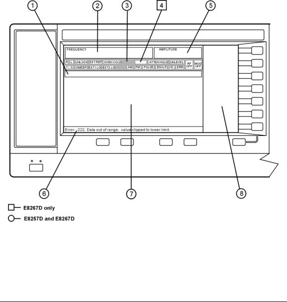
Figure 1- 2 shows the various regions of the PSG display. This section describes each region.
Figure 1-2 |
Front Panel Display Diagram |
1. |
Active Entry Area |
5. |
Amplitude Area |
2. |
Frequency Area |
6. |
Error Message Area |
3. |
Annunciators |
7. Text Area |
|
4. |
Digital Modulation Annunciators |
8. |
Softkey Label Area |
14 |
Chapter 1 |

Signal Generator Overview
Front Panel Display
1. Active Entry Area
The current active function is shown in this area. For example, if frequency is the active function, the current frequency setting will be displayed here. If the current active function has an increment value associated with it, that value is also displayed.
2. Frequency Area
The current frequency setting is shown in this portion of the display. Indicators are also displayed in this area when the frequency offset or multiplier is used, the frequency reference mode is turned on, or a source module is enabled.
3. Annunciators
The display annunciators show the status of some of the signal generator functions and indicate any error conditions. An annunciator position may be used by more than one function. This does not create a problem, because only one function that shares an annunciator position can be active at a time.
ΦM |
This annunciator (Option UNT only) appears when phase modulation is on. If |
|
frequency modulation is on, the FM annunciator replaces ΦM. |
ALC OFF |
This annunciator appears when the ALC circuit is disabled. A second annunciator, |
|
UNLEVEL, appears in the same position if the ALC is enabled and cannot maintain |
|
the output level. |
AM |
This annunciator (Option UNT only) appears when amplitude modulation is on. |
ARMED |
This annunciator appears when a sweep has been initiated and the signal |
|
generator is waiting for the sweep trigger event. |
ATTEN HOLD |
This annunciator (E8267D or E8257D with Option 1E1 only) appears when the |
|
attenuator hold function is on. When this function is on, the attenuator is held at |
|
its current setting. |
DIG BUS |
This annunciator (Options 003/004 only) appears when the digital bus is active, |
|
and the internal oven reference oscillator is not cold (OVEN COLD appears in this |
|
same location). |
ENVLP |
This annunciator appears if a burst condition exists, such as when marker 2 is set |
|
to enable RF blanking in the Dual ARB format. |
ERR |
This annunciator appears when an error message is in the error queue. This |
|
annunciator does not turn off until you either view all the error messages or |
|
cleared the error queue. To access error messages, press Utility > Error Info. |
EXT |
This annunciator appears when external leveling is on. |
EXT1 LO/HI |
This annunciator (Options UNT, UNU, or UNW only) appears as either EXT1 LO or |
|
EXT1 HI, when the accoupled signal to the EXT 1 INPUT is < 0.97 Vp or |
|
> 1.03 Vp. |
EXT2 LO/HI |
This annunciator (Options UNT, UNU, or UNW only) is displayed as either |
|
EXT2 LO or EXT2 HI. This annunciator appears when the accoupled signal to the |
|
EXT 2 INPUT is < 0.97 Vp or > 1.03 Vp. |
Chapter 1 |
15 |

Signal Generator Overview
Front Panel Display
EXT REF |
This annunciator appears when an external frequency reference is applied. |
FM |
This annunciator (Option UNT only) appears when frequency modulation is turned |
|
on. If phase modulation is turned on, the ΦM annunciator will replace FM. |
I/Q |
This annunciator (E8267D only) appears when I/Q modulation is turned on. |
L |
This annunciator appears when the signal generator is in listener mode and is |
|
receiving information or commands over the RS232, GPIB, or VXI11 LAN |
|
interface. |
MOD ON/OFF |
This annunciator (E8267D and E8257D with Options UNT, UNU, or UNW only) |
|
indicates whether active modulation formats have been enabled or disabled. |
|
Pressing the Mod On/Off hardkey enables or disables all active modulation formats |
|
(AM, FM, ΦM, Pulse, or I/Q) that are applied to the output carrier signal available |
|
through the RF OUTPUT connector. The Mod On/Off hardkey does not set up or |
|
activate an AM, FM, ΦM, Pulse, or I/Q format; each individual modulation format |
|
must still be set up and activated (for example, AM > AM On) or nothing will be |
|
applied to the output carrier signal when the Mod On/Off hardkey is enabled. |
OVEN COLD |
This annunciator (Option UNR/UNX only) appears when the temperature of the |
|
internal oven reference oscillator has dropped below an acceptable level. When |
|
this annunciator is on, frequency accuracy is degraded. This condition should |
|
occur for several minutes after the signal generator is first connected to line |
|
power. |
PULSE |
This annunciator (Options UNU or UNW only) appears when pulse modulation is |
|
on. |
R |
This annunciator appears when the signal generator is remotely controlled over |
|
the GPIB, RS232, or VXI11/Sockets LAN interface (TELNET operation does not |
|
activate the R annunciator). When the R annunciator is on, the front panel keys |
|
are disabled, except for the Local key and the line power switch. For information |
|
on remote operation, refer to the Programming Guide. |
RF ON/OFF |
This annunciator indicates when the RF or microwave signal is present (RF ON) or |
|
not present (RF OFF) at the RF OUTPUT. Either condition of this annunciator is |
|
always visible in the display. |
S |
This annunciator appears when the signal generator has generated a service |
|
request (SRQ) over the RS232, GPIB, or VXI11 LAN interface. |
SWEEP |
This annunciator appears when the signal generator is in list, step, or ramp sweep |
|
mode (ramp sweep is available with Option 007 only). List mode is when the |
|
signal generator can jump from point to point in a list (hop list); the list is |
|
traversed in ascending or descending order. The list can be a frequency list, a |
|
power level list, or both. Step mode is when a start, stop, and step value |
|
(frequency or power level) are defined and the signal generator produces signals |
|
that start at the start value and increment by the step value until it reaches the |
|
stop value. Ramp sweep mode (Option 007 only) is when a start and stop value |
|
(frequency or power level) are defined and the signal generator produces signals |
|
that start at the start value and produce a continuous output until it reaches the |
|
stop value. |
T |
This annunciator appears when the signal generator is in talker mode and is |
|
transmitting information over the GPIB, RS232, or VXI11 LAN interface. |
16 |
Chapter 1 |
Loading...