


 Loading...
OPERATING GUIDE for
SOLAR ARRAY SIMULATOR
AGILENT MODELS E4350B, E4351B
Agilent Model E4350B: US37410101 and Above *
Agilent Model E4351B: US37430101 and Above *
* For instruments with higher Serial Numbers, a change page may be included.
Agilent Part No. 5962-8206 |
Printed in USA: |
Microfiche 5962-8207 |
December, 1997 |

CERTIFICATION
Agilent Technologies Company certifies that this product met its published specifications at time of shipment from the factory. Agilent Technologies further certifies that its calibration measurements are traceable to the United States National Bureau of Standards, to the extent allowed by the Bureau’s calibration facility, and to the calibration facilities of other International Standards Organization members.
WARRANTY
This Agilent Technologies hardware product is warranted against defects in material and workmanship for a period of three years from date of delivery. Agilent software and firmware products, which are designated by Agilent for use with a hardware product and when properly installed on that hardware product, are warranted not to fail to execute their programming instructions due to defects in material and workmanship for a period of 90 days from date of delivery. During the warranty period Agilent Technologies Company will, at its option, either repair or replace products which prove to be defective. Agilent does not warrant that the operation of the software, firmware, or hardware shall be uninterrupted or error free.
For warranty service, with the exception of warranty options, this product must be returned to a service facility designated by Agilent. Customer shall prepay shipping charges by (and shall pay all duty and taxes) for products returned to Agilent for warranty service. Except for products returned to Customer from another country, Agilent shall pay for return of products to Customer.
Warranty services outside the country of initial purchase are included in Agilent’s product price, only if Customer pays Agilent international prices (defined as destination local currency price, or U.S. or Geneva Export price).
If Agilent is unable, within a reasonable time to repair or replace any product to condition as warranted, the Customer shall be entitled to a refund of the purchase price upon return of the product to Agilent.
LIMITATION OF WARRANTY
The foregoing warranty shall not apply to defects resulting from improper or inadequate maintenance by the Customer, Customer-supplied software or interfacing, unauthorized modification or misuse, operation outside of the environmental specifications for the product, or improper site preparation and maintenance. NO OTHER WARRANTY IS EXPRESSED OR IMPLIED. AGILENT SPECIFICALLY DISCLAIMS THE IMPLIED WARRANTIES OF MERCHANTABILITY AND FITNESS FOR A PARTICULAR PURPOSE.
EXCLUSIVE REMEDIES
THE REMEDIES PROVIDED HEREIN ARE THE CUSTOMER’S SOLE AND EXCLUSIVE REMEDIES. AGILENT SHALL NOT BE LIABLE FOR ANY DIRECT, INDIRECT, SPECIAL, INCIDENTAL, OR CONSEQUENTIAL DAMAGES, WHETHER BASED ON CONTRACT, TORT, OR ANY OTHER LEGAL THEORY.
ASSISTANCE
The above statements apply only to the standard product warranty. Warranty options, extended support contracts, product maintenance agreements and customer assistance agreements are also available. Contact your nearest Agilent Technologies Sales and Service office for further information on Agilent’s full line of Support Programs.
2

SAFETY SUMMARY
The following general safety precautions must be observed during all phases of operation, service, and repair of this instrument. Failure to comply with these precautions or with specific warnings elsewhere in this manual violates safety standards of design, manufacture, and intended use of the instrument. Agilent Technologies Company assumes no liability for the customer’s failure to comply with these requirements.
BEFORE APPLYING POWER.
Verify that the product is set to match the available line voltage and the correct fuse is installed.
GROUND THE INSTRUMENT.
This product is a Safety Class 1 instrument (provided with a protective earth terminal). To minimize shock hazard, the instrument chassis and cabinet must be connected to an electrical ground. The instrument must be connected to the ac power supply mains through a threeconductor power cable, with the third wire firmly connected to an electrical ground (safety ground) at the power outlet. For instruments designed to be hard-wired to the ac power lines (supply mains), connect the protective earth terminal to a protective conductor before any other connection is made. Any interruption of the protective (grounding) conductor or disconnection of the protective earth terminal will cause a potential shock hazard that could result in personal injury. If the instrument is to be energized via an external autotransformer for voltage reduction, be certain that the autotransformer common terminal is connected to the neutral (earthed pole) of the ac power lines (supply mains).
FUSES.
Only fuses with the required rated current, voltage, and specified type (normal blow, time delay, etc.) should be used. Do not use repaired fuses or short circuited fuseholders. To do so could cause a shock or fire hazard.
DO NOT OPERATE IN AN EXPLOSIVE ATMOSPHERE.
Do not operate the instrument in the presence of flammable gases or fumes.
KEEP AWAY FROM LIVE CIRCUITS.
Operating personnel must not remove instrument covers. Component replacement and internal adjustments must be made by qualified service personnel. Do not replace components with power cable connected. Under certain conditions, dangerous voltages may exist even with the power cable removed. To avoid injuries, always disconnect power, discharge circuits and remove external voltage sources before touching components.
DO NOT SERVICE OR ADJUST ALONE.
Do not attempt internal service or adjustment unless another person, capable of rendering first aid and resuscitation, is present.
DO NOT EXCEED INPUT RATINGS.
This instrument may be equipped with a line filter to reduce electromagnetic interference and must be connected to a properly grounded receptacle to minimize electric shock hazard. Operation at line voltages or frequencies in excess of those stated on the data plate may cause leakage currents in excess of 5.0 mA peak.
SAFETY SYMBOLS.
Instruction manual symbol: the product will be marked with this symbol when it is necessary for the user to refer to the instruction manual (refer to Table of Contents) .
Indicates hazardous voltages.
Indicate earth (ground) terminal.
The WARNING sign denotes a hazard. It calls attention to a procedure, practice, or the like, which, if not correctly performed or adhered to, could result in personal injury. Do not proceed beyond a WARNING sign until the indicated conditions are fully understood and met.
The CAUTION sign denotes a hazard. It calls attention to an operating procedure, or the like, which, if not correctly performed or adhered to, could result in damage to or destruction of part or all of the product. Do not proceed beyond a CAUTION sign until the indicated conditions are fully understood and met.
DO NOT SUBSTITUTE PARTS OR MODIFY INSTRUMENT.
Because of the danger of introducing additional hazards, do not install substitute parts or perform any unauthorized modification to the instrument. Return the instrument to an Agilent Technologies Sales and Service Office for service and repair to ensure that safety features are maintained.
Instruments which appear damaged or defective should be made inoperative and secured against unintended operation until they can be repaired by qualified service personnel.
3

SAFETY SUMMARY (continued)
GENERAL
Any LEDs used in this product are Class 1 LEDs as per IEC 825-l.
ENVIRONMENTAL CONDITIONS
All instruments are intended for indoor use in an installation category II, pollution degree 2 environment. They are designed to operate at a maximum relative humidity of 95% and at altitudes of up to 2000 meters. Refer to the specifications tables for the ac mains voltage requirements and ambient operating temperature range.
SAFETY SYMBOL DEFINITIONS
Symbol |
Description |
Symbol |
Description |
Direct current
Alternating current
Both direct and alternating current
Three-phase alternating current
Earth (ground) terminal
Protective earth (ground) terminal
Frame or chassis terminal
Terminal for Neutral conductor on permanently installed equipment
Terminal is at earth potential(Used for measurement and control circuits designed to be operated with one terminal at earth potential.)
Terminal for Line conductor on permanently installed equipment
Caution, risk of electric shock
Caution, hot surface
Caution (refer to accompanying documents)
In position of a bi-stable push control
Out position of a bi-stable push control
On (supply)
Off (supply)
Standby (supply)
Units with this symbol are not completely disconnected from ac mains when this switch is off. To completely disconnect the unit from ac mains, either disconnect the power cord or have a qualified electrician install an external switch.
Herstellerbescheinigung
Diese Information steht im Zusammenhang mit den Anforderungen der Maschinenläminformationsverordnung vom 18 Januar 1991.
* Schalldruckpegel Lp <70 dB(A) * Am Arbeitsplatz * Normaler Betrieb * Nach EN 27779 (Typprufung).
Manufacturer’s Declaration
This statement is provided to comply with the requirements of the German Sound Emission Directive, from 18 January 1991.
* Sound Pressure Lp <70 dB(A) *At Operator Position |
* Normal Operation |
* According to EN 27779 (Type |
Test). |
|
|
4

DECLARATION OF CONFORMITY
according to ISO/IEC Guide 22 and EN 45014
Manufacturer’s Name: |
Agilent Technologies Company |
Manufacturer’s Address: |
150 Green Pond Road |
|
Rockaway, New Jersey 07866 |
|
U.S.A. |
declares that the Product |
|
Product Name: |
Solar Array Simulator |
Model Number: |
Agilent E4350A, E4350B, E4351B |
conforms to the following Product Specifications: |
|
Safety: |
IEC 1010-1:1990+A1(1992) / EN 61010-1: 1993 |
EMC: |
CISPR 11:1990 / EN 55011:1991 - Group 1 Class A |
|
IEC 801-2:1991 / EN 50082-1:1992 - 4 kV CD, 8 kV AD |
IEC 801-3:1984 / EN 50082-1:1992 - 3 V / m
IEC 801-4:1988 / EN 50082-1:1992 - 0.5 kV Signal Lines 1 kV Power Lines
Supplementary Information:
The product herewith complies with the requirements of the Low Voltage Directive 73/23/EEC and the EMC Directive 89/336/EEC and carries the CE-marking accordingly.
New Jersey |
October 1997 |
|
|
Location |
Date |
|
Bruce Krueger / Quality Manager |
European Contact: Your local Agilent Technologies Sales and Service Office or Agilent Technologies GmbH,
Department TRE, Herrenberger Strasse 130, D-71034 Boeblingen (FAX:+49-7031-14-3143)
PRINTING HISTORY
The edition and current revision of this manual are indicated below. Reprints of this manual containing minor corrections and updates may have the same printing date. Revised editions are identified by a new printing date. A revised edition incorporates all new or corrected material since the previous printing date. Changes to the manual occurring between revisions are covered by change sheets shipped with the manual. In some cases, the manual change applies only to specific instruments. Instructions provided on the change sheet will indicate if a particular change applies only to certain instruments.
© Copyright 1997 Agilent Technologies Company Edition 1 - December, 1997
This document contains proprietary information protected by copyright. All rights are reserved. No part of this document may be photocopied, reproduced, or translated into another language without the prior consent of Agilent Technologies Company. The information contained in this document is subject to change without notice.
5
|
Table Of Contents |
|
1 |
General Information |
|
|
What’s In This Guide? .................................................................................................................................. |
13 |
|
Safety Considerations .................................................................................................................................... |
13 |
|
Options and Accessories................................................................................................................................ |
13 |
|
Operator Replaceable Parts ........................................................................................................................... |
14 |
|
Description .................................................................................................................................................... |
14 |
|
Key Features.................................................................................................................................................. |
14 |
|
Output Characteristic..................................................................................................................................... |
15 |
|
Fixed Mode ............................................................................................................................................. |
15 |
|
Simulator Mode....................................................................................................................................... |
15 |
|
Table Mode ............................................................................................................................................. |
17 |
2 |
Installation |
|
|
Inspection ...................................................................................................................................................... |
19 |
|
Damage.................................................................................................................................................... |
19 |
|
Packaging Material.................................................................................................................................. |
19 |
|
Items Supplied......................................................................................................................................... |
19 |
|
Location and Temperature............................................................................................................................. |
19 |
|
Bench Operation...................................................................................................................................... |
19 |
|
Rack Mounting ........................................................................................................................................ |
20 |
|
Temperature Performance ....................................................................................................................... |
20 |
|
AC Line Connection...................................................................................................................................... |
20 |
|
AC Voltage Conversion ................................................................................................................................ |
21 |
|
VXI plug&play Power Products Instrument Drivers ..................................................................................... |
21 |
|
Downloading and Installing the Driver ................................................................................................... |
22 |
|
Accessing Online Help ............................................................................................................................ |
22 |
3 |
Turn-on Checkout |
|
|
Introduction ................................................................................................................................................... |
23 |
|
Preliminary Checkout .................................................................................................................................... |
23 |
|
Power-on Checkout ....................................................................................................................................... |
23 |
|
Using the Keypad .......................................................................................................................................... |
24 |
|
Shifted Keys ............................................................................................................................................ |
24 |
|
Backspace Key ........................................................................................................................................ |
24 |
|
Output Checkout............................................................................................................................................ |
24 |
|
Checking the Voltage Function ............................................................................................................... |
24 |
|
Checking the Current Function................................................................................................................ |
25 |
|
Checking the Save and Recall Functions....................................................................................................... |
27 |
|
Determining GPIB Address........................................................................................................................... |
27 |
|
In Case of Trouble......................................................................................................................................... |
27 |
|
Line Fuse ................................................................................................................................................. |
27 |
|
Error Messages........................................................................................................................................ |
27 |
|
Selftest Errors.......................................................................................................................................... |
27 |
|
Power-On Error Messages....................................................................................................................... |
27 |
|
Checksum Errors ..................................................................................................................................... |
28 |
|
Runtime Error Messages ......................................................................................................................... |
28 |
4 |
User Connections |
|
|
Rear Panel Connections................................................................................................................................. |
29 |
|
Wire Selection ......................................................................................................................................... |
29 |
|
Analog Connector.................................................................................................................................... |
29 |
|
Digital Connector .................................................................................................................................... |
30 |
|
Load Connections.......................................................................................................................................... |
30 |
|
Output Isolation....................................................................................................................................... |
30 |
6
|
Capacitive Loads ..................................................................................................................................... |
30 |
|
Inductive Loads ...................................................................................................................................... |
31 |
|
Connecting to an External Voltage Source.............................................................................................. |
31 |
|
Sense Connections......................................................................................................................................... |
31 |
|
Remote Voltage Sensing ......................................................................................................................... |
31 |
|
CV Regulation......................................................................................................................................... |
32 |
|
Overvoltage Protection Considerations ................................................................................................... |
32 |
|
Output Rating .......................................................................................................................................... |
32 |
|
Output Noise ........................................................................................................................................... |
32 |
|
Stability ................................................................................................................................................... |
32 |
|
Over Current Protection Considerations........................................................................................................ |
33 |
|
Hardware Overcurrent Circuit ................................................................................................................. |
33 |
|
Operating Configurations .............................................................................................................................. |
33 |
|
Connecting the Load to One Unit ........................................................................................................... |
33 |
|
Connecting Supplies in Parallel............................................................................................................... |
34 |
|
Connecting Supplies in Auto-Parallel...................................................................................................... |
35 |
|
Auto-Parallel Programming Cautions...................................................................................................... |
36 |
|
Connecting Supplies in Series ................................................................................................................. |
37 |
|
Analog Current Control ........................................................................................................................... |
38 |
|
Controller Connections.................................................................................................................................. |
38 |
|
Stand-Alone Connections ........................................................................................................................ |
38 |
|
Linked Connections................................................................................................................................. |
38 |
5 |
Front Panel Operation |
|
|
Introduction ................................................................................................................................................... |
41 |
|
Key Functions................................................................................................................................................ |
41 |
|
Programming the Output ......................................................................................................................... |
44 |
|
Establishing Initial Conditions. ............................................................................................................... |
44 |
|
Programming Voltage ............................................................................................................................. |
44 |
|
Programming Current. ............................................................................................................................. |
45 |
|
Programming Overvoltage Protection ........................................................................................................... |
45 |
|
Setting the OVP Level.............................................................................................................................. |
45 |
|
Checking OVP Operation......................................................................................................................... |
45 |
|
Clearing the OVP Condition .................................................................................................................... |
46 |
|
Programming Overcurrent Protection............................................................................................................ |
46 |
|
Setting the OCP Protection....................................................................................................................... |
46 |
|
Checking OCP Operation ......................................................................................................................... |
46 |
|
Clearing the OCP Condition..................................................................................................................... |
46 |
|
CV Mode vs. CC Mode................................................................................................................................. |
47 |
|
Unregulated Operation .................................................................................................................................. |
47 |
|
Saving and Recalling States .......................................................................................................................... |
47 |
|
Turn-on Conditions ....................................................................................................................................... |
47 |
|
Setting the GPIB Address.............................................................................................................................. |
48 |
|
Types of GPIB Addresses ....................................................................................................................... |
48 |
|
Changing the GPIB Address.................................................................................................................... |
48 |
6. |
Remote Programming |
|
|
GPIB Capabilities of the Power Supply ........................................................................................................ |
49 |
|
Introduction to SCPI...................................................................................................................................... |
49 |
|
Conventions............................................................................................................................................. |
49 |
|
Types of SCPI Commands ............................................................................................................................ |
50 |
|
Multiple Commands in a Message........................................................................................................... |
50 |
|
Moving Among Subsystems .................................................................................................................... |
51 |
|
Value Coupling........................................................................................................................................ |
51 |
|
Including Common Commands ............................................................................................................... |
51 |
|
SCPI Queries ........................................................................................................................................... |
51 |
7
|
Types of SCPI Messages .............................................................................................................................. |
51 |
|
The Message Unit.................................................................................................................................... |
52 |
|
Headers.................................................................................................................................................... |
52 |
|
Query Indicator ....................................................................................................................................... |
52 |
|
Message Unit Separator........................................................................................................................... |
52 |
|
Root Specifier.......................................................................................................................................... |
52 |
|
Message Terminator ................................................................................................................................ |
52 |
|
SCPI Data Formats........................................................................................................................................ |
53 |
|
Numerical Data........................................................................................................................................ |
53 |
|
Suffixes and Multipliers .......................................................................................................................... |
53 |
|
Character Data......................................................................................................................................... |
53 |
|
Examples ....................................................................................................................................................... |
54 |
|
Programming Voltage and Current.......................................................................................................... |
54 |
|
Programming Protection Circuits ............................................................................................................ |
54 |
|
Programming Units in Auto-Parallel ....................................................................................................... |
54 |
|
Changing Outputs by Trigger .................................................................................................................. |
55 |
|
Saving and Recalling States .................................................................................................................... |
55 |
|
Writing to the Display ............................................................................................................................. |
56 |
|
Programming Status ................................................................................................................................ |
56 |
|
Programming the Digital I/O Port ........................................................................................................... |
56 |
|
System Considerations .................................................................................................................................. |
56 |
|
Assigning GPIB Address in Programs..................................................................................................... |
57 |
|
Agilent 82335A Driver Considerations ................................................................................................... |
57 |
|
National Instruments GPIB Driver Considerations ................................................................................. |
57 |
|
BASIC Considerations ............................................................................................................................ |
57 |
7. |
Language Dictionary |
|
|
Introduction ................................................................................................................................................... |
61 |
|
Parameters ............................................................................................................................................... |
61 |
|
Related Commands.................................................................................................................................. |
61 |
|
Order of Presentation .............................................................................................................................. |
61 |
|
Common Commands ............................................................................................................................... |
61 |
|
Subsystem Commands............................................................................................................................. |
61 |
|
Description of Common Commands ............................................................................................................. |
62 |
|
*CLS........................................................................................................................................................ |
62 |
|
*ESE........................................................................................................................................................ |
62 |
|
*ESR?...................................................................................................................................................... |
63 |
|
*IDN? ...................................................................................................................................................... |
63 |
|
*OPC ....................................................................................................................................................... |
64 |
|
*OPC? ..................................................................................................................................................... |
64 |
|
*OPT? ..................................................................................................................................................... |
64 |
|
*PSC........................................................................................................................................................ |
65 |
|
*RCL ....................................................................................................................................................... |
65 |
|
*RST ....................................................................................................................................................... |
66 |
|
*SAV....................................................................................................................................................... |
66 |
|
*SRE ....................................................................................................................................................... |
67 |
|
*STB?...................................................................................................................................................... |
67 |
|
*TRG....................................................................................................................................................... |
68 |
|
*TST?...................................................................................................................................................... |
68 |
|
*WAI....................................................................................................................................................... |
68 |
|
Description of Subsystem Commands ........................................................................................................... |
69 |
|
Calibration Commands .................................................................................................................................. |
71 |
|
Display Subsystem ........................................................................................................................................ |
71 |
|
DISP ........................................................................................................................................................ |
71 |
|
DISP:MODE ........................................................................................................................................... |
71 |
|
DISP:TEXT............................................................................................................................................. |
72 |
8
Measure Subsystem ....................................................................................................................................... |
72 |
MEAS:CURR? ........................................................................................................................................ |
72 |
MEAS:VOLT? ........................................................................................................................................ |
72 |
Memory Subsystem ....................................................................................................................................... |
73 |
MEM:COPY:TABL ................................................................................................................................ |
73 |
MEM:DEL:ALL...................................................................................................................................... |
73 |
MEM:DEL[:NAME] ............................................................................................................................... |
73 |
MEM:TABL:SEL.................................................................................................................................... |
73 |
MEM:TABL:CURR ................................................................................................................................ |
73 |
MEM:TABL:VOLT ................................................................................................................................ |
73 |
MEM:TABL:CURR:POIN?.................................................................................................................... |
74 |
MEM:TABL:VOLT:POIN? .................................................................................................................... |
74 |
MEM:TABL:CAT? ................................................................................................................................. |
74 |
Output Subsystem.......................................................................................................................................... |
74 |
OUTP ...................................................................................................................................................... |
74 |
OUTP:PROT:CLE .................................................................................................................................. |
74 |
OUTP:PROT:DEL .................................................................................................................................. |
75 |
[SOUR:]CURR........................................................................................................................................ |
75 |
[SOUR:]CURR:TRIG ............................................................................................................................. |
75 |
[SOUR:]CURR:MODE........................................................................................................................... |
76 |
[SOUR:]CURR:PROT ............................................................................................................................ |
76 |
[SOUR:]CURR:PROT:STAT ................................................................................................................. |
76 |
[SOUR:]CURR:SAS:ISC ........................................................................................................................ |
77 |
[SOUR:]CURR:SAS:IMP ....................................................................................................................... |
77 |
[SOUR:]CURR:TABL:NAME ............................................................................................................... |
77 |
[SOUR:]CURR:TABL:OFFS.................................................................................................................. |
77 |
[SOUR:]DIG:DATA ............................................................................................................................... |
77 |
[SOUR:]VOLT........................................................................................................................................ |
78 |
[SOUR:]VOLT:TRIG ............................................................................................................................. |
78 |
[SOUR:]VOLT:PROT ............................................................................................................................ |
79 |
[SOUR:]VOLT:SAS:VOC ...................................................................................................................... |
79 |
[SOUR:]VOLT:SAS:VMP...................................................................................................................... |
79 |
[SOUR:]VOLT:TABL:OFFS.................................................................................................................. |
80 |
Status Subsystem ........................................................................................................................................... |
80 |
STAT:OPER?.......................................................................................................................................... |
80 |
STAT:OPER:COND? ............................................................................................................................. |
80 |
STAT:OPER:ENAB................................................................................................................................ |
81 |
STAT:OPER:PTR/NTR .......................................................................................................................... |
81 |
STAT:PRES ............................................................................................................................................ |
81 |
STAT:QUES? ......................................................................................................................................... |
82 |
STAT:QUES:COND? ............................................................................................................................. |
82 |
STAT:QUES:ENAB ............................................................................................................................... |
82 |
STAT:QUES:PTR/NTR.......................................................................................................................... |
83 |
System Commands ........................................................................................................................................ |
83 |
SYST:ERR? ............................................................................................................................................ |
83 |
SYST:VERS? .......................................................................................................................................... |
84 |
Trigger Subsystem......................................................................................................................................... |
84 |
ABOR...................................................................................................................................................... |
84 |
INIT84 |
|
INIT:CONT............................................................................................................................................. |
84 |
TRIG ....................................................................................................................................................... |
85 |
TRIG:SOUR............................................................................................................................................ |
85 |
9
8. |
Status Reporting |
|
|
Agilent SAS Status Structure......................................................................................................................... |
87 |
|
Operation Status Group ................................................................................................................................. |
87 |
|
Register Functions ................................................................................................................................... |
87 |
|
Register Commands................................................................................................................................. |
87 |
|
Questionable Status Group ............................................................................................................................ |
89 |
|
Register Functions ................................................................................................................................... |
89 |
|
Register Commands................................................................................................................................. |
89 |
|
Standard Event Status Group......................................................................................................................... |
89 |
|
Register Functions ................................................................................................................................... |
89 |
|
Register Commands................................................................................................................................. |
89 |
|
Status Byte Register ...................................................................................................................................... |
89 |
|
The RQS Bit ............................................................................................................................................ |
90 |
|
The MSS Bit............................................................................................................................................ |
90 |
|
Determining the Cause of a Service Interrupt.......................................................................................... |
90 |
|
Service Request Enable Register ................................................................................................................... |
90 |
|
Output Queue ................................................................................................................................................ |
90 |
|
Initial Conditions at Power-On...................................................................................................................... |
90 |
|
Status Registers ....................................................................................................................................... |
90 |
|
The PON (Power-On) Bit........................................................................................................................ |
91 |
|
Examples ....................................................................................................................................................... |
91 |
|
Servicing an Operation Status Mode Event............................................................................................. |
91 |
|
Adding More Operation Events............................................................................................................... |
91 |
|
Servicing Questionable Status Events ..................................................................................................... |
91 |
|
Monitoring Both Phases of a Status Transition ....................................................................................... |
92 |
|
SCPI Command Completion ......................................................................................................................... |
92 |
|
DFI (Discrete Fault Indicator) ....................................................................................................................... |
92 |
|
RI (Remote Inhibit) ....................................................................................................................................... |
93 |
|
Using Device Clear ....................................................................................................................................... |
93 |
A |
Specifications and Application Information |
|
|
Specifications and Supplemental Characteristics .......................................................................................... |
95 |
|
Output Impedance Graphs ............................................................................................................................. |
99 |
|
Simulator Mode....................................................................................................................................... |
99 |
|
Fixed Mode ........................................................................................................................................... |
101 |
|
Peak Power Tracker Application ................................................................................................................ |
102 |
|
Exponential Model Equations ............................................................................................................... |
103 |
|
Series Switching Regulation........................................................................................................................ |
104 |
|
Shunt Switching Regulation ........................................................................................................................ |
104 |
B |
Verification and Calibration |
|
|
Introduction ................................................................................................................................................. |
105 |
|
Test Equipment Required ............................................................................................................................ |
105 |
|
Current Monitoring Resistor.................................................................................................................. |
105 |
|
Verification.................................................................................................................................................. |
106 |
|
General Measurement Techniques ........................................................................................................ |
106 |
|
Programming the Agilent SAS .............................................................................................................. |
106 |
|
Order of Tests........................................................................................................................................ |
106 |
|
Turn On Checkout ................................................................................................................................. |
106 |
|
Voltage Programming and Readback Accuracy .................................................................................... |
106 |
|
Current Programming and Readback Accuracy..................................................................................... |
107 |
|
Calibration................................................................................................................................................... |
108 |
|
Test Equipment Required ...................................................................................................................... |
108 |
|
General Procedure ................................................................................................................................. |
108 |
|
Parameters Calibrated............................................................................................................................ |
108 |
|
Front Panel Calibration ............................................................................................................................... |
109 |
10
|
Entering the Calibration Values ............................................................................................................ |
109 |
|
Saving the Calibration Constants........................................................................................................... |
109 |
|
Disabling the Calibration Mode ............................................................................................................ |
109 |
|
Changing the Calibration Password....................................................................................................... |
109 |
|
Recovering From Calibration Problems ................................................................................................ |
111 |
|
Calibration Error Messages ................................................................................................................... |
111 |
|
Calibration over the GPIB ........................................................................................................................... |
111 |
|
Calibration Example.............................................................................................................................. |
111 |
|
Calibration Language Dictionary ................................................................................................................ |
112 |
|
CAL:CURR ........................................................................................................................................... |
112 |
|
CAL:CURR:LEV .................................................................................................................................. |
112 |
|
CAL:PASS ............................................................................................................................................ |
112 |
|
CAL:SAVE ........................................................................................................................................... |
112 |
|
CAL:STAT............................................................................................................................................ |
113 |
|
CAL:VOLT ........................................................................................................................................... |
113 |
|
CAL:VOLT:LEV .................................................................................................................................. |
113 |
|
CAL:VOLT:PROT ................................................................................................................................ |
113 |
|
Agilent Basic Calibration Program.............................................................................................................. |
114 |
C |
Digital Port Functions |
|
|
Digital Connector ........................................................................................................................................ |
117 |
|
Fault/Inhibit Operation ................................................................................................................................ |
117 |
|
Changing the Port Configuration................................................................................................................. |
119 |
|
Digital I/O Operation................................................................................................................................... |
119 |
D |
Error Messages |
|
|
Hardware Error Messages ........................................................................................................................... |
121 |
|
Calibration Error Messages ......................................................................................................................... |
121 |
|
System Error Messages ............................................................................................................................... |
121 |
|
Index .......................................................................................................................................................... |
123 |
|
Agilent Sales and Support Offices ..................................................................................................... |
128 |
11
1
General Information
What’s In This Guide?
This guide describes the Agilent Model E4350B/E4351B Solar Array Simulator (SAS). An overview of the unit is given in this chapter. Installation and user connections are discussed in chapters 2 and 4. Programming from the front panel and over the GPIB is discussed in chapters 5-7. If you just need to check that the unit is operating properly, read chapter 3.
The edition and current revision of this manual are indicated on the title page. Reprints of this manual containing minor corrections and updates may have the same printing date. Revised editions are identified by a new printing date. A revised edition incorporates all new or corrected material since the previous printing date.
Changes to the manual occurring between revisions are covered by change sheets shipped with the manual. In some cases, the manual change applies only to specific instruments. Instructions provided on the change sheet will indicate if a particular change applies only to certain instruments.
Safety Considerations
The Agilent Solar Array Simulator is a Safety Class 1 instrument, which means it has a protective earth terminal. That terminal must be connected to earth ground through a power source equipped with a 3-wire ground receptacle. Refer to the Safety Summary page at the beginning of this guide for general safety information. Before installation or operation, check the Agilent SAS and review this guide for safety warnings and instructions. Safety warnings for specific procedures are located at appropriate places in the guide.
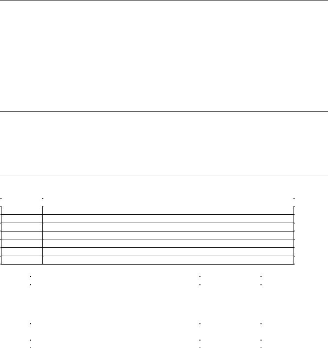
Options and Accessories
|
Table 1-1 Options |
Option |
Description |
100 Input power 100 Vac, nominal
220 Input power 220 Vac, nominal
240 Input power 240 Vac, nominal (for 230 Vac operation, see table A-2 in appendix A)
Rack mount kit (Agilent 5062-3977) Support rails (E3663A) are required.
Rack mount kit (Agilent 5062-3977 & 5062-3974) Support rails (E3663A) are required.
909Rack mount kit with handles (Agilent 5062-3983) Support rails (E3663A) are required.
910Service manual with extra User’s guides
Table 1-2 Accessories |
|
Accessory Description |
Agilent No. |
GPIB cable (all models) |
|
0.5 meters (1.6 ft) |
10833D |
1.0 meter (3.3 ft) |
10833A |
2.0 meters (6.6 ft) |
10833B |
4.0 meters ( 13 .2 ft) |
10833C |
Serial link cable (all models) |
|
2.0 meters (6.6 ft) |
5080-2148 |
Slide mount kit |
1494-0059 |
General Information 13
Operator Replaceable Parts
Description
Cover, dc output Foot, cabinet Fuse, power
100 Vac line voltage, 15 A
120 Vac line voltage, 12 A 220/230/240 Vac line voltage, 7 A
Knob, rotary output control
Table 1-3 Operator Replaceable Parts
Agilent Part No.
0360-2191
5041-8801
2110-0054
2110-0249
21l0-06l4
0370-3238
Description
Plug, analog connector Plug, digital connector Screw, output bus bar Screw, terminal cover
Screw, carrying strap, M5x0.8x10 mm Standoff, GPIB
Agilent Part No.
1252-3698
1252-1488
0515-1085
0515-1085
0515-1132
0380-0644
Description
The Agilent E4350B/E4351B Solar Array Simulator (SAS) is a dc power source that simulates the output characteristics of a solar array. The Agilent SAS is primarily a current source with very low output capacitance. It is capable of simulating the I-V curve of a solar array under different conditions such as temperature and age. The I-V curve is programmable over the IEEE-488.2 bus and is automatically generated within the Agilent SAS. The Agilent SAS has three operating modes:
Fixed Mode: This is the default mode that occurs when the unit is first powered up. The I-V output has the rectangular characteristics of a standard power supply, but with excellent high speed constant current characteristics and low output capacitance. Fixed mode allows front panel programming and is convenient when, in certain applications, the I-V curve is not needed.
Simulator Mode: An internal algorithm is used to simulate a SAS I-V curve. One can easily approximate the curve through four input parameters: open circuit voltage (Voc), short circuit current (Isc), current at the approximate maximum power point on the curve (Imp), and voltage at the approximate maximum power point on the curve (Vmp).
Table Mode: The Agilent SAS provides a table mode for a fast and accurate I-V simulation of solar arrays. In this mode, a table of I-V points, often provided by the solar array manufacturer, specifies the curve. The Agilent SAS provides up to 60 tables with a total of 33,500 I-V points of storage and a maximum of 4,000 I-V points per table. The tables (I-V curves) are easily stored and recalled. A portion of table storage is allocated in non-volatile memory, with 30 possible tables totaling 3,500 points. These are retained when power is turned off. In table mode, current and voltage offsets can be applied to the selected table to simulate a change in the operating conditions of the solar array.
Key Features
■480 Watt output
■Auto-parallel capability for higher power
■Very low output capacitance
■Switching recovery time in less than 5 microseconds
■Programmable overvoltage and over-current protection which are independent of other circuits
■Overtemperature protection
■Fan speed control to minimize acoustic noise
■Extensive set of programming features
■Fast I-V curve change in both table and simulator modes
■Up to 60 volatile/non-volatile tables
■Self test at power-up or from an IEEE-488.2 command
■Serial link to connect up to 16 outputs to one IEEE-488.2 address
■Standard Commands for Programmable Instruments (SCPI)
14 General Information

Output Characteristic
The Agilent E4350B/E4351B Solar Array Simulator can be operated in three modes: fixed mode, simulator mode, and table mode. Mode switching on the Agilent SAS is accomplished over the GPIB bus via the SCPI CURRent:MODE command.
You cannot switch modes from the front panel.
Note: The Agilent SAS must be connected to a computer for you to be able to use the SAS functions that are available in simulator and table modes.
The front panel does not indicate which mode the Agilent SAS is presently operating in. If you are unsure which mode the unit is presently in, you can query the unit over the GPIB using the CURRent:MODE? command. If you cycle power to the unit, it will be in Fixed mode.
Fixed Mode
At power turn on, with *RST, or when executing a Device Clear, the operating state of the Agilent SAS is Fixed mode (see Figure 1-1). In Fixed mode, the output characteristic is similar to that of a standard power supply, except that the output capacitance is <100 nF on the Agilent E4350B, and <50 nF on the Agilent E4351B. This low output capacitance is ideal when using the unit as a constant current source. To use the unit as a low-impedance constant voltage source however, you can add an external output capacitor if so desired. The value of the external capacitor should not exceed 2,000 μF.
|
I |
|
||
E4351B = 4A |
|
MAXIMUM CURRENT |
480W MAX |
|
|
|
|
|
|
E4350B = 8A |
|
|
|
|
I set |
|
TYPICAL FIXED MODE OUTPUT |
|
|
|
|
|
MAXIMUM |
|
|
|
|
||
|
|
|
|
|
|
|
|
|
VOLTAGE |
|
|
|
|
|
V
0 Vset 120V = E4351B
60V = E4350B
Figure 1-1. Fixed Mode Characteristic
Restrictions
■If the programmed values exceed the maximum current and voltage boundaries by more than 2 or 3 percent, an OUT OF RANGE error will be indicated.
Simulator Mode
Simulator mode uses an exponential model to approximate the I-V curve (see Figure 1-2). It is programmed in terms of its open circuit voltage (Voc), short circuit current (Isc), voltage point (Vmp), and current point (Imp) at approximately the peak power point (see page A-9 in appendix A for model equations). Simulator mode operation is achieved by sampling the output voltage, applying a low-pass filter, and continually adjusting the constant current loop by using the filtered voltage as an index into the exponential model.
General Information 15

|
I |
|
|
E4351B = 4A |
MAXIMUM CURRENT |
480W MAX |
|
E4350B = 8A |
|
|
|
I sc |
TYPICAL CURVE |
Pmp |
|
I mp |
|
MAXIMUM |
|
|
|
VOLTAGE |
|
|
|
V |
= 1Ω min (E4351B) |
|
POINTS UNDER |
I |
.25Ω min (E4350B) |
|
DASHED LINE |
|
|
|
ARE INVALID |
|
|
0 |
Vmp |
Voc |
|
|
V |
|
|
|
|||
|
|
120V |
130V = E4351B |
||
|
|
60V |
65V = E4350B |
||
|
|
|
|
|
|
Figure 1-2. Simulator Mode Characteristic
Note that under certain conditions, such as if Imp is significantly less than Isc, the model equation will exhibit a certain degree of inaccuracy in that the actual maximum power point (Pmp) and value may be somewhat different from the expected value of Pmp (Imp x Vmp). Thus the actual Pmp point may not occur at exactly the Imp x Vmp. This can be corrected by entering new values for Imp and Vmp (see Figure A-1 in appendix A).
Also note that the accuracy specifications in simulator mode are relative to the values given in the exponential equations, and not necessarily to the input parameters Imp and Vmp. However, the Isc and Voc values are always accurately given by the exponential equations.
Restrictions:
■Maximum Power £ 480 W
■Voc £ 130 V (E4351B) or 65 V (E4350B)
■Isc £ 4 A (E4351B) or 8 A (E4350B)
■Vmp < Voc
■Imp £ Isc
■DV/DI ³ .25 W for Agilent E4350B; ³ 1 W for Agilent E4351B
NOTE: When the unit detects invalid equation parameters, it will generate an error, light the ERR annunciator on the front panel, and will not use the new parameters. Instead, it will operate with the last valid settings. Therefore, although it may seem that the unit is operating correctly, it will NOT be using the values that you have programmed for simulator mode.
If simulator mode is entered with no parameters specified, |
|
E4350B |
E4351B |
the default values that will be used are: |
Voc |
61.5 V |
123 V |
|
Vmp |
49.2 V |
98.4 V |
|
Imp |
6.528 A |
3.264 A |
|
Isc |
8.16 A |
4.08 A |
|
Pmp |
321.2 W |
321.2 W |
|
|
|
|
16 General Information

Front panel operation:
You can use the front panel when the unit is operating in Simulator mode. To do this, press the Local key whenever the front panel RMT annunciator is on. Be aware however, that any voltage and current values that you enter from the front panel will have no effect on the unit while it is in Simulator mode. These front panel values will take effect as soon as the unit is placed in Fixed mode. Likewise, the OCP function only takes effect in Fixed mode. All other functions such as Local, Error, Output On/Off, Protect are active while the unit is operating in Simulator mode.
Table Mode
In Table mode, the output characteristic is determined by a user-defined table of voltage/current points (see Figure 1-3). Table mode operation is achieved by sampling the output voltage, applying a low-pass filter, and continually adjusting the constant current loop by using the filtered voltage as an index into the stored table of points. Linear interpolation is used to set the current when the filtered voltage does not have an exactly matching table entry. What this means is that the I-V curve is generated by connecting the points in the table by straight lines. The more points that you provide, the more accurate the curve will be when the points are connected.
|
|
I |
|
|
E4351B = 4A |
MAXIMUM CURRENT |
480W MAX |
||
E4350B = 8A |
|
|
|
|
I |
sc |
TYPICAL CURVE |
|
|
|
|
|
|
|
|
|
|
MAXIMUM |
|
|
|
|
VOLTAGE |
|
|
|
|
V |
= 1Ω min (E4351B) |
|
|
POINTS UNDER |
I |
|
|
|
.25Ω min (E4350B) |
||
|
|
|
||
|
|
DASHED LINE |
|
|
|
|
ARE INVALID |
|
|
|
V oc |
V |
0 |
130V = E4351B |
|
|
120V |
|
|
60V |
65V = E4350B |
Figure 1-3. Table Mode Characteristic
Each table can have a maximum of 4,000 output points (3,500 points if it will be stored in non-volatile memory). Each output point is defined by a voltage/current coordinate pair of values that define the location of the point on the curve. The first value is the voltage, the second value is the current. If no point is supplied for V=0, the current associated with the lowest voltage entry point is defined as Isc and the curve will be extended horizontally to the current axis. If no point is supplied for I=0, the slope that was determined by the last two current entry points will be extended to the voltage axis.
Multiple tables can be defined and saved in non-volatile memory (which is limited to 3500 points), or volatile memory (which is limited to 30,000 points). Up to 30 tables can be saved in each memory.
Restrictions
■The number of points in a table can vary from 3 to 4000, but an equal number of voltage and current values must be sent. Otherwise an error will occur when the table is selected with CURRent:TABLe:NAME. Use MEMory:TABLe:CURRent:POINts? and MEMory:TABLe:VOLTage:POINts? to find the length of an existing table.
■Points must be above dashed line shown in Figure 1-3.
General Information 17

■There is no restriction on the spacing between points in either voltage or current, but the points must be monotonic. Voltage values must be sent in increasing order of magnitude; current values must be sent in equal or decreasing order of magnitude. For an Agilent E4350B for example: (1,8) (50,7.8) (55,7.5) (56,7) (57, 6) (58, 4) (59,1).
■Each table point, when combined with the table offset, cannot exceed the unit’s maximum voltage, current, or power.
■A table cannot be deleted or redefined while it is selected with CURRent:TABLe:NAME.
■Maximum Power £ 480 W
■DV/DI ³ .25 W for Agilent E4350B; ³ 1 W for Agilent E4351B Voc £ 65V (Agilent E4350B); 130V (Agilent E4351B)
Isc £ 8A (Agilent E4350B); 4A (Agilent E4351B)
The Vmp and Imp points are calculated internally and need not be supplied.
NOTE: When the unit detects an invalid voltage/current point, it will generate an error, light the ERR annunciator on the front panel, and will not use the new parameters. Instead, it will operate with the last valid table settings. Therefore, although it may seem that the unit is operating correctly, it will NOT be using the values that you have programmed for table mode.
Table Offsets:
A new table can be generated by applying a limited voltage or current offset to an existing table. This can be helpful in simulating temperature, angular, rotational, or aging changes. Offset values are non-cumulative, they can be either positive or negative, and can be applied to any table. Each time a voltage or current offset is programmed, a new I-V curve is calculated based on the user-defined table that is presently active and the supplied offset values. Offset values affect the original I-V curve as follows:
Positive Voltage Offsets: The original curve is shifted to the right ( ) along the positive voltage axis, and the first point on the curve is extended horizontally at Isc until it intersects the current axis. Thus, the new Voc equals the original Voc plus the offset value. An error will be generated if the offset causes the maximum allowed Voc or the power limit to be exceeded.
Negative Voltage Offsets: The original curve is offset to the left ( ) along the positive voltage axis, and terminated at the current axis. The curve points that are not used because they extended beyond the current axis are not deleted; they will be valid once again if the negative voltage offset is reduced or eliminated.
Positive Current Offsets: The original curve is offset up ( ) along the positive current axis, and the last point on the curve will be extended (at the same slope that was present in the original table curve at Voc) until it intersects the voltage axis at a new, slightly higher Voc value. The new Isc equals the original Isc plus the offset value. An error will be generated if the offset causes the maximum allowed Isc, Voc, or the power limit to be exceeded.
Negative Current Offsets: The original curve is offset down ( ) along the positive current axis, and terminated at the voltage axis at a new, lower Voc value. The curve points that are not used because they are extended beyond the voltage axis are not deleted; they will be valid once again if the negative current offset is reduced or eliminated.
Front panel operation:
You can use the front panel when the unit is operating in Table mode. To do this, press the Local key whenever the front panel RMT annunciator is on. Be aware however, that any voltage and current values that you enter from the front panel will have no effect on the unit while it is in Table mode. The front panel values will take effect as soon as the unit is placed in Fixed mode. Likewise, the OCP function only takes effect in Fixed mode. All other functions such as Local, Error, Output On/Off, Protect are active while the unit is operating in Simulator mode.
18 General Information

2
Installation
Inspection
Damage
When you receive your Agilent SAS, inspect it for any obvious damage that may have occurred during shipment. If there is damage, notify the shipping carrier and the nearest Agilent Sales and Support Office immediately. Warranty information is printed in the front of this guide.
Packaging Material
Until you have checked out the Agilent SAS, save the shipping carton and packing materials in case the Agilent SAS has to be returned to Agilent Technologies . If you return the Agilent SAS for service, attach a tag identifying the model number and the owner. Also include a brief description of the problem.
Items Supplied
In addition to this manual, check that the following items in Table 2-1 are included with your Agilent SAS
Table 2-1. Items Supplied
Power cord Your Agilent SAS was shipped with a power cord for the type of outlet specified for your location. If the appropriate cord was not included, contact your nearest Agilent Sales and Support Office (see end of this guide) to obtain the correct cord. Caution: The Agilent SAS cannot use a standard power cord. The power cords supplied by Agilent Technologies have heavier gauge wire.
Analog connector
Digital connector
Serial cable
A 7-terminal analog plug (see table 1-3 in chapter 1) that connects to the back of the unit. Analog connections are described in chapter 4.
A 4-terminal digital plug (see table 1-3 in chapter 1) that connects to the back of the unit. Digital connections are described in appendix C - Digital Port Functions
A 2-meter cable (see table 1-2 in chapter 1) that connects to the control bus (next to the GPIB connector). This cable is used to serially connect multiple supplies as described under Controller Connections in Chapter 4.
Change page If applicable, change sheets may be included with this guide. If there are change sheets, make the indicated corrections in this guide.
Location and Temperature
Bench Operation
The Supplemental Characteristics in appendix A give the dimensions of your Agilent SAS. The cabinet has plastic feet that are shaped to ensure self-alignment when stacked with other Agilent System II cabinets. The feet may be removed for rack mounting. Your Agilent SAS must be installed in a location that allows sufficient space at the sides and rear of the cabinet for adequate air circulation. Minimum clearances are 1 inch (25 mm) along the sides. Do not block the fan exhaust at the rear of the unit.
Installation 19

Rack Mounting
The Agilent SAS can be mounted in a standard l9-inch rack panel or cabinet. Rack mounting kits are available as Option 908 or 909 (with handles). Installation instructions are included with each rack mounting kit.
Support rails are required when rack-mounting the Agilent SAS (see table 1-1).
Temperature Performance
A variable-speed fan cools the unit by drawing air through the sides and exhausting it out the back. Using Agilent rack mount or slides will not impede the flow of air. The Agilent SAS operates without loss of performance within the temperature range of 0 °C to 40 °C and with derated output current from 40 °C to 55 °C (see appendix A).
If the Agilent SAS is operated at full output current for several hours, the sheet metal immediately under the transformer (near the right front) can get very hot. Do not touch this area of the cabinet. The line cord also can become quite warm. Both of these conditions are normal.
AC Line Connection
Refer to the applicable paragraphs below for information on the ac line. Do not apply power to the Agilent SAS until directed to do so in Chapter 3.
Check the line Rating label on the rear of your unit and verify that the voltage shown there corresponds to the nominal line voltage of your ac line. If it does not, see AC Line Voltage Conversion for instructions on changing the Agilent SAS line voltage configuration.
The supplied cord connects to the power receptacle on the rear panel ( , Figure 2-l).
■You can operate your Agilent SAS from a nominal 100 V, 120 V, 220 V, 230 V, or 240 V single-phase ac line as indicated on the rear panel line Rating label .
■See "AC Input Ratings" in table A-l or table A-2 in appendix A for the voltage and frequency range for the Agilent SAS. Refer to "Maximum AC Line Current Ratings" for the maximum load current.
■The line fuse is located in a fuseholder on the rear panel . The rear panel label shows the fuse value used in the unit. See Operator Replaceable Parts in chapter 1 for replacement fuse information.
Figure 2-1. Agilent SAS Power Connection
20 Installation

AC Line Voltage Conversion
SHOCK HAZARD. Hazardous voltage can remain inside the unit even after it has been turned off. This procedure should only be done by qualified electronics service personnel.
Line voltage conversion is accomplished by changing wire and jumper positions on the ac input of the main power transformer. Proceed as follows:
1.Turn off the ac power to the unit and disconnect the power cord from the ac line.
2.Remove the four screws that secure the two carrying straps and outer cover.
3.Slightly spread the bottom rear of the cover and pull it back to disengage it from the front panel.
4.Slide the dust cover back far enough to expose the line select jumpers (see figure 2-2).
5.Move the line voltage select jumpers to the positions corresponding to the desired line voltage. To disconnect it from the transformer tab, pull the wire straight up. Moving the wire from side-to-side can damage the tab.
7.Replace the top cover and secure the carrying straps.
8.Change the line fuse (on the rear panel) to the proper value for the new line voltage .
Figure 2-2. Agilent SAS Line Select Jumpers
VXI plug&play Power Products Instrument Drivers
VXI plug&play Power Products instrument drivers for Microsoft Windows 95 and Windows NT are now available on the Web at http://www.agilent.com/find/drivers. These instrument drivers provide a high-level programming interface to your Agilent Power Products instrument. VXI plug&play instrument drivers are an alternative to programming your instrument with SCPI command strings. Because the instrument driver’s function calls work together on top of the VISA I/O library, a single instrument driver can be used with multiple application environments.
|
Supported Applications |
|
System Requirements |
|
Agilent VEE |
The VXI plug&play Power Products instrument driver |
|
|
Microsoft Visual BASIC |
complies with the following: |
|
|
Microsoft Visual C/C++ |
|
Microsoft Windows 95 |
|
Borland C/C++ |
|
Microsoft Windows NT 4.0 |
|
National Instruments LabVIEW |
|
HP VISA revision F.01.02 |
|
National Instruments LabWindows/CVI |
|
National Instruments VISA 1.1 |
Installation 21

Downloading and Installing the Driver
NOTE: Before installing the VXI plug&play instrument driver, make sure that you have one of the supported applications installed and running on your computer.
1.Access Agilent Technologies’ Web site at http://www.agilent.com/find/drivers.
2.Select the instrument for which you need the driver.
3.Click on the driver, either Windows 95 or Windows NT, and download the executable file to your pc.
4.Locate the file that you downloaded from the Web. From the Start menu select Run <path>:\agxxxx.exe - where <path> is the directory path where the file is located, and agxxxx is the instrument driver that you downloaded .
5.Follow the directions on the screen to install the software. The default installation selections will work in most cases. The readme.txt file contains product updates or corrections that are not documented in the on-line help. If you decide to install this file, use any text editor to open and read it.
6.To use the VXI plug&play instrument driver, follow the directions in the VXI plug&play online help under “Introduction to Programming”.
Accessing Online Help
A comprehensive online programming reference is provided with the driver. It describes how to get started using the instrument driver with Agilent VEE, LabVIEW, and LabWindows. It includes complete descriptions of all function calls as well as example programs in C/C++ and Visual BASIC.
To access the online help when you have chosen the default Vxipnp start folder, click on the Start button and select Programs | Vxipnp | Agxxxx Help (32-bit).
- where Agxxxx is the instrument driver.
22 Installation

3
Turn-On Checkout
Introduction
Successful tests in this chapter provide a high degree of confidence that the Agilent SAS is operating properly. For verification tests, see appendix B under Verification. Do not apply ac power to the Agilent SAS until told to do so.
Note |
This chapter provides a preliminary introduction to the Agilent SAS front panel. See chapter 5 - Front |
|
Panel Operation for more details. During this procedure, the Agilent SAS is operating in Fixed mode. |
Preliminary Checkout
1.Make certain that the front panel switch is off.
2.Examine the Line Fuse Rating label on the rear panel.
a.Verify that the line voltage rating agrees with your ac line. If it does not, see chapter 2 under AC Line Voltage Conversion.
b.Use a screwdriver to remove the line fuse from the fuseholder. Verify that the fuse is as specified on the label. Replace the fuse.
3.Check that the SENSE switch is set to Local.
4.Make sure that there is no load connected to the output terminals or bus bars.
Power-On Checkout
1.Connect the power cord to the unit.
2.Turn the front panel power switch to ON (1).
3.The Agilent SAS undergoes a self-test when you turn it on. If the test is normal, the following sequence appears on the LCD:
a.a brief star-burst pattern which lights all the LCDs, followed by
b.A D D R 5 the GPIB address (factory default is 5).
4.The display then goes into the meter mode with the Dis annunciator on and all others off. “Meter mode” means that the VOLTS digits indicate the output voltage and the AMPS digits indicate the output current. These values will be at or near zero.
5.Verify that the Agilent SAS fan is on by placing your hand near the rear grill to feel the air flow. You may also be able to hear the fan operating.
6.Press  once. The Dis annunciator will go off and the CV annunciator will go on .
Note |
If the Agilent SAS detects an error during self-test, the display will show an error message. Go to “In Case |
|
of Trouble” at the end of this chapter. |
|
|
Turn-On Checkout 23

Using The Keypad
Shifted Keys
Some of the front panel keys perform two functions, one labeled in black and the other in blue. You access the blue function by first pressing the blue  key, which is not labeled. When the Shift annunciator is on, you will know you have access to the key’s shifted (blue) function.
Backspace Key
The  key is an erase key. If you make a mistake entering a number and have not yet entered it (have not pressed
 ), you can delete the number by pressing
  . You may delete as many numbers as you wish by repeatedly pressing this key.
Output Checkout
Important When the Agilent SAS is turned on, it asserts the state stored in EEPROM memory location 0. For a new unit, this is the factory default (*RST) state. The following procedures assume that the factory default state is still in location 0 (see Turn-On Conditions in chapter 5 for details).
Checking the Voltage Function
The tests in Table 3-1 check the basic voltage functions with no load connected to the Agilent SAS. These test are possible only from the front panel when the unit is operating in Fixed mode. The VOLTS display will show various readings. Ignore the AMPS display.
Table 3-1. Checking the Voltage Functions with Output Terminals Open
Procedure |
Display |
Explanation |
Either leave the output terminals open or connect them to a voltmeter.
If the Dis annunciator is on, turn it off by pressing |
|
|
||||
Press |
key |
|
VOLT 0.000 |
|
Default voltage setting. CV annunciator should be on. (If CC annunicator |
|
|
|
|||||
|
|
|
|
|
is on, increase the current by pressing |
one or more times until |
|
|
|
|
|
CC turns off and CV turns on.) |
|
|
|
|
|
|
|
|
Press |
|
|
VOLT 40 |
|
Program output to 40 volts. |
|
Press |
|
|
|
|
Enter the voltage. Meter mode displays output voltage. During these |
|
|
|
40.00 |
|
|||
|
|
|
|
|
tests, there may be a small (relative to full output) AMPS reading that |
|
|
|
|
|
|
will be ignored. |
|
Press |
several |
|
|
|
Voltage decreases several millivolts each time you press the key. |
|
|
|
|
||||
times |
|
|
|
|
|
|
Press |
the same |
|
|
|
Voltage increases several millivolts each time you press the key. |
|
|
|
|
||||
number of times |
|
|
|
|
|
|
|
|
|
|
|
|
|
24 Turn-On Checkout

Table 3-1. Checking the Voltage Functions with Output Terminals Open (continued)
Procedure
Rotate the Voltage control first counterclockwise and then clockwise
Press
Press 
Press 
Press
Press 
Press 
Press 

Display |
|
Explanation |
|
|
Control operates similarly to |
and |
keys. The control |
is rate sensitive. Turning it more quickly causes a more rapid change in voltage.
40.00 |
Program the output to 40 volts. |
|
|
Display shows default OVP (overvoltage protection) trip voltage for your |
|
|
||
|
unit (see Supplemental Characteristics in appendix A). |
|
OV 30 |
Program the OVP to 30 volts, which is less than the output voltage. |
|
0.000 |
OVP voltage entered is less than the output voltage. This causes the OVP |
|
|
circuit to trip. The output drops to zero, CV turns off, and Prot turns on. |
|
OV - - - - - |
Shows that the Agilent SAS shuts down because the OVP circuit has |
|
|
tripped. |
|
|
Return display to meter mode (optional step). |
|
|
||
0.000 |
Program the OVP to 50 volts, which is greater than the output voltage. |
|
|
Note: You cannot clear an OVP trip until you have first removed the |
|
|
cause of the condition. |
|
|
|
Press Prot Clear |
|
40.00 |
The OVP circuit is cleared, restoring the output. Prot turns off and CV |
( |
)* |
|
turns on. |
|
|
|
|
* is the unlabeled blue key.
Checking the Current Function
The tests in Table 3-2 check the basic current functions with a short connected across the Agilent SAS output. These tests are possible only from the front panel when the unit is operating in Fixed mode. Do not program maximum output currents unless the shorting wire is capable of handling the current (see Supplemental Characteristics in appendix A and table 4-1). The AMPS display will show various readings. Ignore the VOLTS display.
Table 3-2. Checking the Current Functions with Output Terminals Shorted
Action |
Display |
Explanation |
|
|
|
Turn off the Agilent SAS and connect a #18 AWG or larger wire across the output (+) and (-) terminals. If you intend to test at full-rated output current, use a wire or wires of sufficient size to carry the maximum current of the unit (see Supplemental Characteristics in appendix A and table 4-1 in Chapter 4).
Turn on the unit. |
Meter mode |
Essentially zero outputs with Dis annunciator on. |
Set the voltage to its maximum |
|
|
value. This example assumes that |
|
|
you have an 60-volt unit (see |
|
|
Table 7-3 for the value for your |
|
|
specific unit). |
|
|
|
|
|
Turn-On Checkout 25

Table 3-2. Checking the Current Functions with Output Terminals Shorted (continued)
Action |
Display |
Explanation |
|
|
|
Press 

Press 

Press 
Press  several times
Press  the same number of times
Rotate the Current control first counterclockwise and then clockwise
Press 
Press 
Press 
Press 
(
 )*
)*
Press 
VOLT 60.000 |
Program output to 60 volts. |
|
|
|
AMPS 1.000 |
Program output to 1 ampere. |
|
|
|
|
|
|||
AMPS 1. 000 |
Dis annunciator turns off, CC annunciator turns on, and AMPS |
|||
|
display shows the programmed current. The output voltage |
|
||
|
should be close to zero volts. |
|
|
|
|
Current decreases several milliamperes each time you press the |
|||
|
key. |
|
|
|
|
Current increases several milliamperes each time you press the |
|||
|
||||
|
key. |
|
|
|
|
Control operates similarly to the |
and |
keys. |
|
|
||||
|
The control is rate sensitive. Turning it more quickly causes a |
|||
|
more rapid change in current. |
|
|
|
|
You have enabled the overcurrent protection circuit. The circuit |
|||
|
||||
|
then tripped because of the output short. The CC annunciator |
|||
|
turns off and the OCP and Prot annunciators come on. The |
|
||
|
output current is near zero. Note that the overcurrent protection |
|||
|
circuit is disabled in Simulator and in Table modes. |
|
||
AMPS 0.000 |
Dis annunciator turns on. |
|
|
|
|
|
|||
|
You have disabled the overcurrent protection circuit. The OCP |
|||
|
||||
|
annunciator turns off. |
|
|
|
|
You have cleared the overcurrent protection circuit. The Prot |
|||
|
||||
|
annunciator turns off. |
|
|
|
AMPS 1.000 |
Dis turns off and CC turns on. The output current is restored. |
|||
|
|
|
|
|
If you have a shorting wire of sufficient capacity, you may continue testing up to the maximum rated current of the Agilent SAS (see Performance Specifications in appendix A). When finished, go to the next step.
Press |
AMPS 0.000 |
Dis turns on and output current drops to zero. |
|
|
|
Turn off the Agilent SAS and remove the short from the output terminals.
* is the unlabeled blue key.
26 Turn-On Checkout
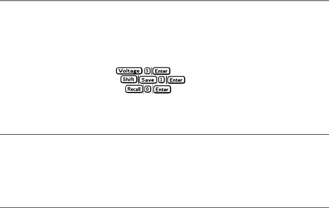
Checking The Save And Recall Functions
The Save and Recall functions are applicable to the Agilent SAS in Fixed mode only. Note that in Simulator or in Table modes, the Save function is ignored, the recall will return the unit to the Fixed mode and reset the parameters to the *RST values (refer to the discussion of *RCL in chapter 7). The Agilent SAS has five nonvolatile memory storage locations (0 through 4). Proceed as follows:
■Make certain that the output is on (Dis annunciator is off).
■ Set the voltage output to 5 by pressing |
. |
|
■ |
Save this value to location 1 by pressing |
. |
■ |
Return the output voltage to 0 by pressing |
(This step is based on the fact that a newly shipped |
Agilent SAS has the *RST parameters stored in location 0 (see chapter 5 - Front Panel Operation for more information).
■Press 
 and notice that the output voltage returns to the value stored in location 1.
Determining The GPIB Address
When the Agilent SAS is turned on, the display shows ADDR n, where n is the Agilent SAS GPIB address. Any time you want to see the address, press  .
.
The display will indicate ADDR 5, which is the factory default. If the address has been changed, then a different number will appear (see Setting the GPIB Address in chapter 5).
In Case Of Trouble
Line Fuse
If your unit appears dead with a blank display and the fan not running, first check your ac line to be certain that voltage is being supplied to the Agilent SAS. If the power source is normal, the Agilent SAS line fuse may be defective. If the unit has a defective fuse, replace it only once. If it fails again, investigate the reason for the failure.
The line fuse is located on the rear panel. To change the fuse proceed as follows:
1.Turn off the front panel power switch.
2.Using a screwdriver, remove the fuse from the fuseholder. Replace it with one of the same type (see table 1-3 in chapter l).
3.Turn on the Agilent SAS and check the operation.
Error Messages
Agilent SAS failure may occur during power-on selftest or during operation. In either case, the display may show an error message that indicates the reason for the failure.
Selftest Errors
When a selftest error occurs, it prevents all front panel operation. The display may show either a power-on error message or a checksum error message.
Power-On Error Messages
Power-on messages appear as: En- - - - - -
Where "n" is a number listed in Table 3-3. If this occurs, turn the power off and then back on to see if the error persists. It is possible to recover from the EE CHKSUM error (see "Checksum Errors"). If any other message persists, the Agilent SAS requires service.
Turn-On Checkout 27

|
|
Table 3-3. Power-On Selftest Errors |
|
||
Error |
Display |
Failed Test |
Error |
Display |
Failed Test |
No. |
|
|
No. |
|
|
El |
FP RAM |
Front Panel RAM |
E8 |
SEC RAM |
Secondary RAM |
E2 |
FP ROM |
Front Panel ROM checksum |
E9 |
SEC ROM |
Secondary ROM checksum |
E3 |
EE CHKSUM |
EEPROM |
E10 |
SEC 5V |
Secondary 5 V ADC reading |
E4 |
PRI XRAM |
Primary external RAM |
Ell |
TEMP |
Secondary ambient |
E5 |
PRI IRAM |
Primary internal RAM |
|
|
thermistor reading |
E6 |
PRI ROM |
Primary ROM checksum |
E12 |
DACS |
Secondary VDAC/IDAC |
E7 |
GPIB |
GPB R/W to serial poll |
|
|
readback |
Checksum Errors.
If the display shows EE CHKSUM, the Agilent SAS has detected an EEPROM checksum error. A checksum error can occur due to the following conditions:
■Excessive number of write cycles to an EEPROM (see "Supplemental Characteristics"). This condition, which would appear only after extended use, is not recoverable and requires service.
■Loss of ac input power during a checksum calculation. This condition, which is very unlikely, is recoverable.
You may be able to recover from a checksum error by writing to the EEPROM while the Agilent SAS is in the calibration mode. To do this, proceed as follows:
1.Enable the calibration mode by pressing 
 .
.
2.PASWD will appear on the display.
3.Press the number keys corresponding to the password, followed by  . The Cal annunciator will go on.
Note On new equipment, the default calibration password corresponds to the model number (such as 4350). See appendix B under Changing the Calibration Password for more information.
4.Save any operating state (for example, press 
 ).
).
5.Turn the power off and then back on.
A normal display free of error messages should appear. If not, the Agilent SAS requires service.
Runtime Error Messages
Under unusual operating conditions, the VOLT or AMPS display may show +OL or -OL. This indicates that either the output voltage or current is beyond the range of the meter readback circuit, or that the value that is programmed is out of range. Table 3-4 shows other error messages that may appear at runtime.
|
Table 3-4. Runtime Errors |
|
|
Display |
Meaning |
Display |
Meaning |
EE WRITE ERR |
EEPROM status timeout |
UART FRAMING |
UART byte framing error |
SBUF FULL |
Message too long for buffer |
UART OVERRUN |
Overfilled UART receive buffer |
SERIAL DOWN |
Failed communication with |
UART PARITY |
UART byte parity error panel |
|
front panel |
|
|
STK OVERFLOW |
Front panel stack overflow |
|
|
28 Turn-On Checkout

4
User Connections
Rear Panel Connections
Make application load connections to the output terminals or bus bars, analog connector, and digital connector as shown on the rear-panel drawing for your model Agilent SAS. Make controller connections (GPIB and serial link) as shown in Figure 4-12 at the end of this chapter.
Wire Selection
Fire Hazard To satisfy safety requirements, load wires must be large enough not to overheat when carrying the maximum short-circuit current of the Agilent SAS. If there is more than one load, then any pair of load wires must be capable of safely carrying the full-rated current of the unit.
Table 4-1 lists the characteristics of AWG (American Wire Gauge) copper wire.
|
Table 4-1. Wire Characteristics |
|
|
AWG No. |
Ampacity (in free air) |
Resistance (at 20 deg. C) |
|
|
|
Ω/m |
Ω/ft |
20 |
8.33 |
0.0345 |
0.01054 |
18 |
15.4 |
0.0217 |
0.00663 |
16 |
19.4 |
0.0137 |
0.00417 |
14 |
31.2 |
0.0086 |
0.00262 |
12 |
40 |
0.0054 |
0.00165 |
Analog Connector
This connector, which is on the rear panel, is for connecting remote sense leads, external current monitors, and external current programming sources. The connector accepts wires sizes from AWG 22 to AWG 12.
IP |
IP |
SAS |
P |
IM |
S |
S |
+ |
- |
- |
sI |
- |
+ |
- |
2
1
|
Insert Wires |
κ |
Tighten screws |
+IP |
Differential current programming input (positive). |
−IP |
Differential current programming input (negative). |
−SAS |
Auto-parallel output connection (SAS mode only). |
Pσ |
Common output for -IM and -SAS signals. |
−IM |
Current monitor output (referenced to Pσ). |
+ S |
remote sense input (positive). |
−S |
remote sense input (negative). |
|
Figure 4-1. Rear Panel Analog Connector |
|
|
Note |
It is good engineering practice to twist or shield all signal wires to and from the analog and digital |
|
connectors. |
|
To minimize spurious operation, make sure that all analog wiring except for the + and − sense wires does |
|
not exceed 3 meters in length. |
|
|
User Connections 29

Digital Connector
This connector, which is on the rear panel, is for connecting fault/inhibit, digital I/O, or relay link signals. The connector accepts wires sizes from AWG 22 to AWG 12.
|
|
|
|
Pin No. |
Fault/Inhibit1 |
Digital I/O |
|
|
1 |
FLT OUTPUT |
OUT 0 |
||
|
|
2 |
FLT OUTPUT |
OUT 1 |
||
|
|
3 |
INH INPUT |
IN/OUT 2 |
||
|
|
4 |
INH COMMON |
COMMON |
||
|
|
|
|
|
||
Insert Wires |
Tighten Screws |
|
|
1 Factory |
default function is |
FAULT/INHIBIT. |
|
Figure 4-2. Rear Panel Digital Connector |
|
||||
Load Connections
5
1
|
-I |
|
|
|
|
6 |
|
+240 VDC |
I P |
I P SAS P I M S |
S |
SENSE |
|
|
- |
|
+ |
- - s - + |
- |
|
|
|
+ |
|
|||
|
4 |
- |
|
|
Local |
|
|
|
|
|
|
Remote |
|
2 |
|
|
|
|
|
|
|
M4 x 0.7 x 8mm |
|
|
|
|
|
3 |
|
|
|
|
|
|
Output Safety Cover |
+ Output Terminal |
|
|
- Output Terminal |
||
Chassis ground (Earth) |
Output Sense Switch |
|
|
Analog Connector |
||
Figure 4-3. SAS Rear Panel Output Connections
Output Isolation
The output of the Agilent SAS has dc isolation from earth ground. Either output terminal may be grounded, or an external voltage source may be connected between either output and ground. However, both output terminals must be kept within ±240 Vdc of ground. An earth ground terminal is provided on the rear panel for convenience, such as grounding wire shields.
The earth ground terminal on the rear panel is a low-noise signal ground for convenience only. It is not designed to function as a safety ground.
Capacitive Loads
In Fixed Mode Operation, the maximum external capacitance that may be added to the output without causing instability is 2,000 μF. This is also the maximum capacitance value that can be safely discharged by the OVP (overvoltage protection) circuit.
30 User Connections
Loading...