


Agilent
E4438C ESG Vector
Signal Generator
Data Sheet
Notice
Please contact Agilent Technologies for the latest information
or check the ESG Web site at www.agilent.com/find/esg
Table of Contents
Introduction . . . . . . . . . . . . . . . . . . . . . . . . . . . . . . . . . . . . . . . . . . . . . . . . . . . . . . . . . . . . . . . .3 Key Features . . . . . . . . . . . . . . . . . . . . . . . . . . . . . . . . . . . . . . . . . . . . . . . . . . . . . . . . . . . . . . .4 Specifications for Frequency and Power Characteristics . . . . . . . . . . . . . . . . . . . . . . . . . . .5 Frequency . . . . . . . . . . . . . . . . . . . . . . . . . . . . . . . . . . . . . . . . . . . . . . . . . . . . . . . . . . . . .5 Sweep modes . . . . . . . . . . . . . . . . . . . . . . . . . . . . . . . . . . . . . . . . . . . . . . . . . . . . . . . . . .5 Internal reference oscillator . . . . . . . . . . . . . . . . . . . . . . . . . . . . . . . . . . . . . . . . . . . . . .5 Output power . . . . . . . . . . . . . . . . . . . . . . . . . . . . . . . . . . . . . . . . . . . . . . . . . . . . . . . . . .6 Level accuracy . . . . . . . . . . . . . . . . . . . . . . . . . . . . . . . . . . . . . . . . . . . . . . . . . . . . .6 Repeatability and linearity . . . . . . . . . . . . . . . . . . . . . . . . . . . . . . . . . . . . . . . . . . .8 Spectral purity . . . . . . . . . . . . . . . . . . . . . . . . . . . . . . . . . . . . . . . . . . . . . . . . . . . . . . . .10
Specifications for Analog Modulation . . . . . . . . . . . . . . . . . . . . . . . . . . . . . . . . . . . . . . . . . .12 Frequency bands . . . . . . . . . . . . . . . . . . . . . . . . . . . . . . . . . . . . . . . . . . . . . . . . . . . . . .12 Frequency modulation . . . . . . . . . . . . . . . . . . . . . . . . . . . . . . . . . . . . . . . . . . . . . . . . . .12 Phase modulation . . . . . . . . . . . . . . . . . . . . . . . . . . . . . . . . . . . . . . . . . . . . . . . . . . . . . .13 Amplitude modulation . . . . . . . . . . . . . . . . . . . . . . . . . . . . . . . . . . . . . . . . . . . . . . . . . .13 Wideband AM . . . . . . . . . . . . . . . . . . . . . . . . . . . . . . . . . . . . . . . . . . . . . . . . . . . . . . . . .14 Pulse modulation . . . . . . . . . . . . . . . . . . . . . . . . . . . . . . . . . . . . . . . . . . . . . . . . . . . . . .14 Internal modulation source . . . . . . . . . . . . . . . . . . . . . . . . . . . . . . . . . . . . . . . . . . . . . .15 External modulation inputs . . . . . . . . . . . . . . . . . . . . . . . . . . . . . . . . . . . . . . . . . . . . . .15 External burst envelope . . . . . . . . . . . . . . . . . . . . . . . . . . . . . . . . . . . . . . . . . . . . . . . . .16 Composite modulation . . . . . . . . . . . . . . . . . . . . . . . . . . . . . . . . . . . . . . . . . . . . . . . . . .16 Simultaneous modulation . . . . . . . . . . . . . . . . . . . . . . . . . . . . . . . . . . . . . . . . . . . . . . .16
Specifications for I/Q Characteristics . . . . . . . . . . . . . . . . . . . . . . . . . . . . . . . . . . . . . . . . . .17 I/Q modulation bandwidth . . . . . . . . . . . . . . . . . . . . . . . . . . . . . . . . . . . . . . . . . . . . . .17 I/Q adjustments . . . . . . . . . . . . . . . . . . . . . . . . . . . . . . . . . . . . . . . . . . . . . . . . . . . . . . .18 Baseband generator [arbitrary waveform mode] . . . . . . . . . . . . . . . . . . . . . . . . . . . . .19 Baseband generator [real-time mode] . . . . . . . . . . . . . . . . . . . . . . . . . . . . . . . . . . . . .20
Specifications for Signal Personality Characteristics . . . . . . . . . . . . . . . . . . . . . . . . . . . . .21 3GPP W-CDMA . . . . . . . . . . . . . . . . . . . . . . . . . . . . . . . . . . . . . . . . . . . . . . . . . . . . . . . .21 IS-95 CDMA . . . . . . . . . . . . . . . . . . . . . . . . . . . . . . . . . . . . . . . . . . . . . . . . . . . . . . . . . .22 cdma2000 . . . . . . . . . . . . . . . . . . . . . . . . . . . . . . . . . . . . . . . . . . . . . . . . . . . . . . . . . . . .22 Enhanced multitone . . . . . . . . . . . . . . . . . . . . . . . . . . . . . . . . . . . . . . . . . . . . . . . . . . . .23
AWGN . . . . . . . . . . . . . . . . . . . . . . . . . . . . . . . . . . . . . . . . . . . . . . . . . . . . . . . . . . .23 802.11 WLAN . . . . . . . . . . . . . . . . . . . . . . . . . . . . . . . . . . . . . . . . . . . . . . . . . . . .24 Custom modulation . . . . . . . . . . . . . . . . . . . . . . . . . . . . . . . . . . . . . . . . . . . . . . .25 GSM/GPRS . . . . . . . . . . . . . . . . . . . . . . . . . . . . . . . . . . . . . . . . . . . . . . . . . . . . . .26 EDGE/EGPRS . . . . . . . . . . . . . . . . . . . . . . . . . . . . . . . . . . . . . . . . . . . . . . . . . . . .27 GSM/EDGE base station bit error rate test [BERT] . . . . . . . . . . . . . . . . . . . . . .28
Bit error rate [BER] analyzer . . . . . . . . . . . . . . . . . . . . . . . . . . . . . . . . . . . . . . . . . . . . .29 General Characteristics . . . . . . . . . . . . . . . . . . . . . . . . . . . . . . . . . . . . . . . . . . . . . . . . . . . . .30 Operating characteristics . . . . . . . . . . . . . . . . . . . . . . . . . . . . . . . . . . . . . . . . . . . . . . .30 Inputs and outputs . . . . . . . . . . . . . . . . . . . . . . . . . . . . . . . . . . . . . . . . . . . . . . . . . . . . .31 Ordering Information . . . . . . . . . . . . . . . . . . . . . . . . . . . . . . . . . . . . . . . . . . . . . . . . . . . . . . . .37 Related Literature . . . . . . . . . . . . . . . . . . . . . . . . . . . . . . . . . . . . . . . . . . . . . . . . . . . . . . . . . .38
2

Introduction
E4438C ESG
vector signal generator
Definitions
Agilent Technologies E4438C ESG vector signal generator incorporates a broad array of capabilities for testing both analog and digital communications systems. Flexible options provide test solutions that will evaluate the performance of nearly all current and proposed air interface standards. Many test functions can be customized to meet the needs of proprietary and other nonstandard wireless protocols as well. You can configure your instrument to address a wide variety of tests—from altering nearly every aspect of a digital signal or signal operating environment, to creating experimental signals. This flexibility, along with an architecture that accepts future enhancements makes the E4438C ESG vector signal generator an excellent choice for wireless communications system testing now and in the future.
Choose your required frequency range as an Option when configuring your
E4438C ESG vector signal generator. Please refer to the E4438C Configuration Guide for complete ordering information. Literature number 5988-4085EN.
Specifications (spec): Specifications describe the instrument’s warranted performance and apply after a 45 minute warm-up. All specifications are valid over the signal generators entire operating/environmental range unless otherwise noted. Supplemental characteristics, denoted typical or nominal, provide additional [nonwarranted] information useful in applying the instrument. Column headings labeled “standard” imply that this level of performance is standard, without regard for option configuration. If a particular option configuration modifies the standard performance, that performance is given in a separate column.
Typical (typ): performance is not warranted. It applies at 25°C. 80% of all products meet typical performance.
Nominal (nom): values are not warranted. They represent the value of a parameter that is most likely to occur; the expected or mean value. They are included to facilitate the application of the product.
Standard (std): No options are included when referring to the signal generator unless noted otherwise.
3

Key Features
Key standard features
Optional features
•Expandable architecture
•Broad frequency coverage
•Choice of electronic or mechanical attenuator
•Superior level accuracy
•Wideband FM and FM
•Step and list sweep, both frequency and power
•Built-in function generator
•Lightweight, rack-mountable
•1-year standard warranty
•2-year calibration cycle
•Broadband analog I/Q inputs
•I/Q adjustment capabilities and internal calibration routine
•Excellent modulation accuracy and stability
•Coherent carrier output up to 4 GHz
•Internal baseband generator, 8 or 64 MSa (40 or 320 MB) memory with digital bus capability
•ESG digital input or output connectivity with N5102A Baseband Studio digital signal interface module
•6 GB internal hard drive
•Internal bit error rate (BER) analyzer
•High-stability time-base
•Enhanced phase noise performance
•High output power with mechanical attenuator
•Move all front panel connectors to the rear panel
•3GPP W-CDMA FDD personality
•cdma2000 and IS-95-A personality
•TDMA personality (GSM, EDGE, GPRS, EGPRS, NADC, PDC, PHS, DECT, TETRA)
•Calibrated noise (AWGN) personality
•GPS personality
•Signal Studio for 1xEV-DO/1xEVDO Rev A
•Signal Studio for 1xEV-DV and cdma2000
•Signal Studio for 802.11 WLAN
•Signal Studio for Bluetooth™
•Signal Studio for enhanced multitone
•Signal Studio for HSDPA over W-CDMA
•Signal Studio for TD-SCDMA
•Signal Studio for Noise Power Ratio (NPR)
•Signal Studio for S-DMB
•Signal Studio for T-DMB
•Signal Studio for pulse building
•Signal Studio for jitter injection
•Signal Studio toolkit
•Signal Studio for 802.16-2004 (WiMAX)
•Signal Studio for 802.16 OFDMA
•Signal Studio for DVB
This document contains the measured specifications for the instrument platform and personalities. It does not contain a full list of features for all optional personalities. Please consult the individual product overviews for each personality for a full listing of all features and capabilities. These are listed
at the end of this document.
4

Specifications for Frequency and Power Characteristics
Frequency |
Frequency range |
Option 1
501250 kHz to 1 GHz
502250 kHz to 2 GHz
503250 kHz to 3 GHz
504250 kHz to 4 GHz
506 |
250 kHz to 6 GHz [requires Option UNJ] |
|
|
||||
|
|
|
|
|
|
|
|
Frequency minimum |
100 kHz 2 |
|
|
|
|
||
Frequency resolution |
0.01 Hz |
|
|
|
|
||
|
|
|
|
|
|
||
Frequency switching speed 3 |
|
|
|
|
|||
|
|
Option 501-504 |
With Option UNJ |
Option 506 |
|||
|
|
Freq.4 |
Freq./Amp.5 |
Freq.4 |
Freq./Amp.5 |
Freq.4 Freq./Amp.5 |
|
|
Digital modulation |
|
|
|
|
|
|
|
on |
(< 35 ms) (< 49 ms) |
(< 35 ms) (< 52 ms) |
(< 41 ms) (< 57 ms) |
|||
|
off |
(< 9 ms) |
(< 9 ms) |
(< 9 ms |
(< 9 ms) |
(< 16 ms (< 17 ms) |
|
|
[For hops < 5 MHz within a band] |
|
|
|
|
||
|
Digital modulation |
|
|
|
|
|
|
|
on |
(< 9 ms) |
(< 9 ms) |
(< 9 ms) |
(< 9 ms) |
(< 33 ms) (< 53 ms) |
|
|
off |
(< 9 ms) |
(< 9 ms) |
(< 9 ms) |
(< 9 ms) |
(< 12 ms) (< 14 ms) |
|
Phase offset Phase is adjustable remotely [LAN, GPIB, RS-232] or via front panel in nominal 0.1° increments
Sweep modes
Internal reference oscillator
Operating modes Frequency step, amplitude step and arbitrary list
Dwell time |
1 ms to 60 s |
|
||
|
|
|
|
|
Number of points |
2 to 65,535 |
|
||
|
|
|
|
|
|
|
|
|
|
Stability3 |
|
|
|
|
|
|
|
Standard |
With Option UNJ or 1E5 |
|
Aging rate |
|
< ±1 ppm/yr |
< ±0.1 ppm/yr or |
|
|
|
|
< ±0.0005 ppm/day after 45 days |
|
Temp [0 to 55° C] |
(< ±1 ppm) |
(< ±0.05 ppm) |
|
|
Line voltage |
|
(< ±0.1 ppm) |
(< ±0.002 ppm) |
|
Line voltage range |
(+5% to –10%) |
(+5% to –10%) |
|
|
|
|
|
|
RF reference output |
|
|
|
|
|
Frequency |
|
10 MHz |
|
|
Amplitude |
|
4 dBm ±2 dB |
|
RF reference input requirements |
|
||
|
|
Standard |
With Option UNJ or 1E5 |
|
Frequency |
1, 2, 5, 10 MHz ± 10 ppm |
1, 2, 5, 10 MHz ±.2 ppm |
|
Amplitude |
–3.5 dBm to 20 dBm |
|
|
Input impedance |
50 Ω |
|
|
|
|
|
1.The E4438C is available as a vector platform only. For analog models refer to the E4428C.
2.Performance below 250 kHz not guaranteed.
3.Parentheses denote typical performance.
4.To within 0.1 ppm of final frequency above 250 MHz or within 100 Hz below 250 MHz.
5.Frequency switching time with the amplitude settled within ±0.1 dB.
5
Specifications for Frequency and Power Characteristics
Output power
1.Quoted specifications for 23 °C ± 5 °C. Accuracy degrades by less than 0.03 dB/°C over full temperature range. Accuracy degrades by 0.3 dB above +7 dBm, and by 0.8 dB above +10 dBm.
2.Parentheses denote typical performance.
3.Quoted specifications for 23 °C ± 5 °C. Accuracy degrades by less than 0.03 dB/°C over full temperature range. Accuracy degrades by 0.2 dB above +10 dBm, and by 0.8 dB above +13 dBm.
4.Quoted specifications for 23 °C ± 5 °C. Accuracy degrades by less than 0.02 dB/°C over full temperature range. Accuracy degrades by 0.2 dB above +7 dBm.
Power
|
Option 501-504 |
With Option UNB |
Option 506 |
250 kHz to 250 MHz |
+11 to –136 dBm |
+15 to –136 dBm |
+12 to –136 dBm |
> 250 MHz to 1 GHz |
+13 to –136 dBm |
+17 to –136 dBm |
+14 to –136 dBm |
> 1 to 3 GHz |
+10 to –136 dBm |
+16 to –136 dBm |
+13 to –136 dBm |
> 3 to 4 GHz |
+7 to –136 dBm |
+13 to –136 dBm |
+10 to –136 dBm |
> 4 to 6 GHz |
N/A |
N/A |
+10 to –136 dBm |
Typical maximum available power
|
26 |
|
|
|
|
|
|
|
24 |
|
Option UNB |
|
|
|
|
|
|
|
|
|
Option 506 |
|
|
|
22 |
|
|
|
|
|
|
|
|
|
|
|
|
|
|
[dB] |
20 |
|
|
|
|
|
|
18 |
|
|
|
|
|
|
|
Power |
|
|
|
|
|
|
|
16 |
|
|
|
|
|
|
|
|
|
|
|
|
|
|
|
|
14 |
Option 501-504 |
|
|
|
|
|
|
|
|
|
|
|
||
|
12 |
|
|
|
|
|
|
|
10 |
|
2000 |
|
|
|
|
|
0 |
1000 |
3000 |
4000 |
5000 |
6000 |
|
Frequency [MHz]
Level resolution |
|
0.02 dB |
|
|
||
|
|
|
|
|
||
Level range with Attenuator Hold active |
|
|
||||
|
|
|
Option 501-504 With Option UNB |
Option 506 |
||
|
250 kHz to 1 GHz |
23 dB |
27 dB |
|
24 dB |
|
|
> 1 to 3 GHz |
20 dB |
26 dB |
|
23 dB |
|
|
> 3 to 4 GHz |
17 dB |
23 dB |
|
20 dB |
|
|
> 4 to 6 GHz |
N/A |
N/A |
|
20 dB |
|
|
|
|
|
|
|
|
Level accuracy [dB] |
|
|
|
|
||
|
Option 501-504 1,2 |
|
|
|
|
|
|
|
|
|
Power level |
|
|
|
|
|
+7 to |
–50 to |
–110 to |
< –127 dBm |
|
|
|
–50 dBm |
–110 dBm |
–127 dBm |
|
|
250 kHz to 2.0 GHz |
±0.5 |
±0.5 |
±0.7 |
(±1.5) |
|
|
2.0 to 3 GHz |
±0.6 |
±0.6 |
±0.8 |
(±2.5) |
|
|
3 to 4 GHz |
±0.7 |
±0.7 |
±0.9 |
(±2.5) |
|
|
|
|
|
|
|
|
|
With Option UNB 2 , 3 |
|
|
|
|
|
|
|
|
|
Power level |
|
|
|
|
|
+10 to |
–50 to |
–110 to |
< –127 dBm |
|
|
|
–50 dBm |
–110 dBm |
–127 dBm |
|
|
250 kHz to 2.0 GHz |
±0.5 |
±0.7 |
±0.8 |
(±1.5) |
|
|
2.0 to 3 GHz |
±0.6 |
±0.8 |
±1.0 |
(±2.5) |
|
|
3 to 4 GHz |
±0.8 |
±0.9 |
±1.3 |
(±2.5) |
|
|
|
|
|
|
|
|
|
Option 506 2, 4 |
|
|
|
|
|
|
|
|
|
Power level |
|
|
|
|
|
+7 to |
–50 to |
–110 to |
< –127 dBm |
|
|
|
–50 dBm |
–110 dBm |
–127 dBm |
|
|
250 kHz to 2.0 GHz |
±0.6 |
±0.8 |
±0.8 |
(±1.5) |
|
|
2.0 to 3 GHz |
±0.6 |
±0.8 |
±1.0 |
(±2.5) |
|
|
3 to 4 GHz |
±0.8 |
±0.9 |
±1.5 |
(±2.5) |
|
|
4 to 6 GHz |
±0.8 |
±0.9 |
(±1.5) |
|
|
6

Specifications for Frequency and Power Characteristics
Level accuracy with digital modulation turned on [relative to CW] Conditions: [with PRBS modulated data;
if using I/Q inputs, √ I2 + Q2 = 0.5 Vrms, nominal] 1
Level accuracy with ALC on
π/4 DQPSK or QPSK formats
Conditions: With raised cosine or root-raised cosine filter and a ≥ 0.35; with 10 kHz ≤ symbol rate ≤ 1 MHz; at RF freq ≥ 25 MHz; power ≤ max specified –3 dB
|
Option 501-504 |
Option 506 |
|
|
|
|
±0.15 dB |
±0.25 dB |
|
|
|
|
Constant amplitude formats [FSK, GMSK, etc] |
|
|
||
|
Option 501-504 |
Option 506 |
|
|
|
|
±0.1 dB |
|
±0.15 dB |
|
|
|
|
|
|
||
Level accuracy with ALC off 1, 2 |
(±0.15 dB) [relative to ALC on] |
|
|||
|
Conditions: |
After power search is executed, with burst off. |
|||
|
|
|
|
|
|
Level switching speed 1 |
|
|
|
|
|
|
|
|
Option 501-504 |
With Option UNB |
Option 506 |
|
Normal operation [ALC on] |
|
(< 15 ms) |
(< 21 ms) |
(< 21 ms) |
|
When using power search manual |
(< 83 ms) |
(< 95 ms) |
(< 95 ms) |
|
|
When using power search auto |
(< 103 ms) |
(< 119 ms) |
(< 119 ms) |
|
|
|
|
|
|
|
1.Parentheses denote typical performance.
2.When applying external I/Q signals with ALC off, output level will vary directly with I/Q input level.
7
Specifications for Frequency and Power Characteristics
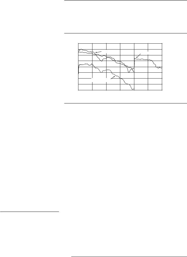
Repeatability and linearity
Repeatability |
Repeatability |
1900 MHz CW, 5 dBm, attenuator hold On, ALC On |
1900 MHz CW, 5 dBm, attenuator hold Off, ALC Off |
0.1 |
|
|
|
|
|
0.5 |
0.09 |
|
|
|
|
Typical unit |
0.45 |
|
|
|
|
|
|
|
0.08 |
|
|
|
|
Limits |
0.4 |
|
|
|
|
|
||
0.07 |
|
|
|
|
|
0.35 |
0.06 |
|
|
|
|
|
0.3 |
0.05 |
|
|
|
|
|
0.25 |
0.04 |
|
|
|
|
|
0.2 |
(dB)Powererror |
|
|
|
|
|
(dB)errorPower |
0.03 |
|
|
|
|
|
0.15 |
0.02 |
|
|
|
|
|
0.10 |
0.01 |
|
|
|
|
|
0.05 |
0 |
|
|
|
|
|
0 |
0 |
20 |
40 |
60 |
80 |
100 |
120 |
|
|
|
|
|
|
|
|
Typical unit |
|
|
|
|
|
|
|
|
|
|
Limits |
|
|
0 |
1 |
2 |
3 |
4 |
5 |
6 |
7 |
8 |
9 |
10 |
Elapsed time (minutes) |
Elapsed time (minutes) |
Repeatability measures the ability of the instrument to return to a given power setting after a random excursion to any other frequency and power setting. It is a relative measurement that reflects the difference in dB between the maximum and minimum power readings for a given setting over a specific time interval. It should not be confused with absolute power accuracy, which is measured in dBm.1
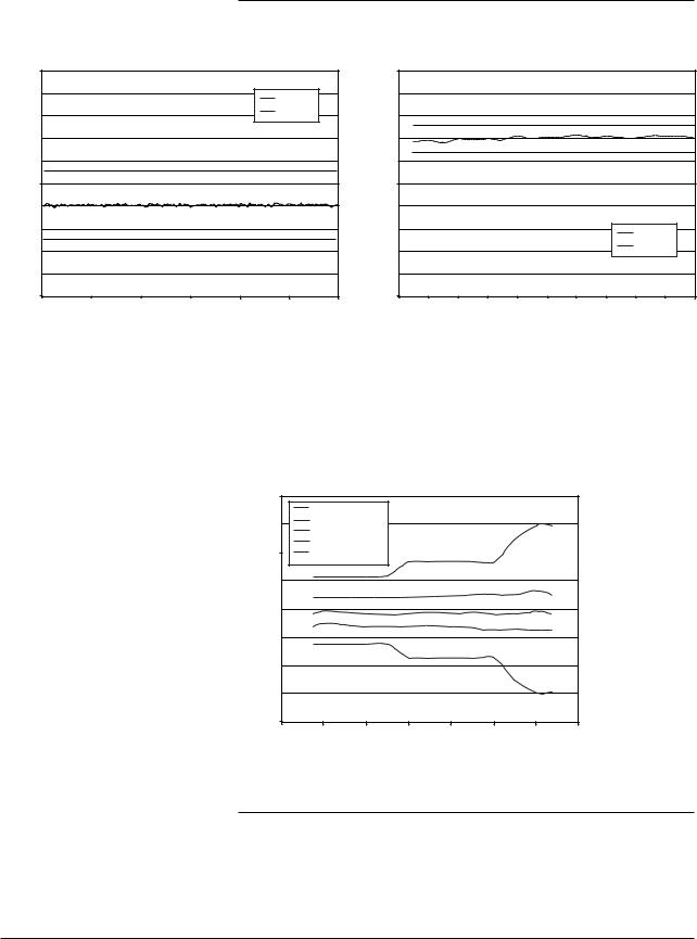
Relative level accuracy
Initial power 7 dBm
|
0.4 |
|
|
|
|
|
|
|
|
|
Lower limit |
|
|
|
|
|
|
|
0.3 |
Lower STD deviation |
|
|
|
|
|
|
|
Mean |
|
|
|
|
|
|
|
|
|
|
|
|
|
|
|
|
|
|
Upper STD deviation |
|
|
|
|
|
|
|
0.2 |
Upper limit |
|
|
|
|
|
|
|
0.1 |
|
|
|
|
|
|
|
(dB) |
0 |
|
|
|
|
|
|
|
error |
|
|
|
|
|
|
|
|
|
|
|
|
|
|
|
|
|
Power |
-0.1 |
|
|
|
|
|
|
|
|
|
|
|
|
|
|
|
|
|
-0.2 |
|
|
|
|
|
|
|
|
-0.3 |
|
|
|
|
|
|
|
|
-0.4 |
|
|
|
|
|
|
|
|
0 |
-20 |
-40 |
-60 |
-80 |
-100 |
-120 |
-140 |
Final power (dBm)
Relative level accuracy measures the accuracy of a step change from any power level to any other power level. This is useful for large changes (i.e. 5 dB steps).1
1. Repeatability and relative level accuracy are typical for all frequency ranges.
8

Specifications for Frequency and Power Characteristics
ALC offset error (dB)
|
|
|
|
|
|
Linearity |
|
|
|
|
|
|
|
|
|
|
CW or GSM, 850 MHz, attenuator hold On, ALC On |
|
|
||||||||
0.3 |
|
|
|
|
|
|
|
|
|
|
|
|
|
0.25 |
|
|
|
|
|
Typical STD unit |
|
|
|
|
|
||
|
|
|
|
|
|
|
|
|
|
|
|
|
|
0.2 |
|
|
|
|
|
Typical Option UNB unit |
|
|
|
|
|||
|
|
|
|
|
Typical Option 506 unit |
|
|
|
|
||||
|
|
|
|
|
|
|
|
|
|
||||
0.15 |
|
|
|
|
|
Lower limit |
|
|
|
|
|
|
|
|
|
|
|
|
|
|
|
|
|
|
|
||
0.1 |
|
|
|
|
|
Upper limit |
|
|
|
|
|
|
|
0.05 |
|
|
|
|
|
|
|
|
|
|
|
|
|
0 |
|
|
|
|
|
|
|
|
|
|
|
|
|
-0.05 |
|
|
|
|
|
|
|
|
|
|
|
|
|
-0.1 |
|
|
|
|
|
|
|
|
|
|
|
|
|
-0.15 |
|
|
|
|
|
|
|
|
|
|
|
|
|
-0.2 |
|
|
|
|
|
|
|
|
|
|
|
|
|
-0.25 |
|
|
|
|
|
|
Limit is undefined above 13 dBM |
|
|
||||
|
|
|
|
|
|
|
|
|
|||||
-0.3 |
|
|
|
|
|
|
for STD units. Limit line applies |
|
|
||||
-0.35 |
|
|
|
|
|
|
only to UNB and 506 units. |
|
|
|
|||
|
|
|
|
|
|
|
|
|
|
|
|
|
|
-0.4 |
|
|
|
|
|
|
|
|
|
|
|
|
|
-10 |
-8 |
-6 |
-4 |
-2 |
0 |
2 |
4 |
6 |
8 |
10 |
12 |
14 |
16 |
|
|
|
|
|
|
Amplitude (dBm) |
|
|
|
|
|
||
Linearity measures the accuracy of small changes while the attenuator is held in a steady state (to avoid power glitches). This is useful for fine resolution changes.1
Linearity |
Linearity |
CW or GSM, 1900 MHz, attenuator hold On, ALC On |
W-CDMA 2200 MHz, attenuator hold On, ALC On |
|
0.3 |
|
|
|
|
|
|
|
|
|
|
|
|
|
0.3 |
|
0.25 |
|
|
|
|
Typical STD unit |
|
|
|
|
|
|
|
0.25 |
|
|
0.2 |
|
|
|
|
Typical Option 506 unit |
|
|
|
|
|
|
0.2 |
||
|
|
|
|
|
Typical Option UNB unit |
|
|
|
|
|
|
||||
|
|
|
|
|
|
|
|
|
|
|
|
|
|||
|
0.15 |
|
|
|
|
Lower limit |
|
|
|
|
|
|
|
0.15 |
|
|
0.1 |
|
|
|
|
Upper limit |
|
|
|
|
|
|
|
0.1 |
|
(dB) |
|
|
|
|
|
|
|
|
|
|
|
|
(dB) |
||
0.05 |
|
|
|
|
|
|
|
|
|
|
|
|
0.05 |
||
error |
|
|
|
|
|
|
|
|
|
|
|
|
error |
||
0 |
|
|
|
|
|
|
|
|
|
|
|
|
0 |
||
offset |
|
|
|
|
|
|
|
|
|
|
|
|
offset |
||
-0.05 |
|
|
|
|
|
|
|
|
|
|
|
|
-0.05 |
||
ALC |
-0.1 |
|
|
|
|
|
|
|
|
|
|
|
|
ALC |
-0.1 |
|
|
|
|
|
|
|
|
|
|
|
|
|
|
||
|
-0.15 |
|
|
|
|
|
|
|
|
|
|
|
|
|
-0.15 |
|
-0.2 |
|
|
|
|
|
|
|
|
|
|
|
|
|
-0.2 |
|
-0.25 |
|
|
|
|
|
|
|
|
|
|
|
|
|
-0.25 |
|
-0.3 |
|
|
|
|
|
|
|
|
|
|
|
|
|
-0.3 |
|
-10 |
-8 |
-6 |
-4 |
-2 |
0 |
2 |
4 |
6 |
8 |
10 |
12 |
14 |
16 |
|
|
|
|
|
|
Typical STD unit |
|
|
|
|
|
|
|
|
|
Typical Option UNB unit |
|
|
||
|
|
|
|
|
Typical Option 506 unit |
|
|
|
|
|
|
|
|
|
Lower limit |
|
|
|
|
|
|
|
|
|
Upper limit |
|
|
|
|
-10 |
-8 |
-6 |
-4 |
-2 |
0 |
2 |
4 |
6 |
8 |
Amplitude (dBm) Amplitude (dBm)
Linearity |
Linearity |
CW or GSM 5750 MHz, attenuator hold On, ALC On |
W-CDMA 5750 MHz, attenuator hold On, ALC On |
|
0.3 |
|
|
|
|
|
|
|
|
|
|
0.3 |
|
0.25 |
|
|
|
Typical STD unit |
|
|
Lower limit |
|
|
|
0.25 |
|
|
|
|
Lower STD deviation |
|
Upper limit |
|
|
|
|||
|
|
|
|
|
|
|
|
|
|
|||
|
0.2 |
|
|
|
Upper STD deviation |
|
|
|
|
|
0.2 |
|
|
0.15 |
|
|
|
|
|
|
|
|
|
|
0.15 |
(dB) |
0.1 |
|
|
|
|
|
|
|
|
|
(dB) |
0.1 |
0.05 |
|
|
|
|
|
|
|
|
|
0.05 |
||
error |
|
|
|
|
|
|
|
|
|
error |
||
0 |
|
|
|
|
|
|
|
|
|
0 |
||
offset |
|
|
|
|
|
|
|
|
|
Offset |
||
-0.05 |
|
|
|
|
|
|
|
|
|
-0.05 |
||
ALC |
-0.1 |
|
|
|
|
|
|
|
|
|
ALC |
-0.1 |
|
|
|
|
|
|
|
|
|
|
|
||
|
-0.15 |
|
|
|
|
|
|
|
|
|
|
-0.15 |
|
-0.2 |
|
|
|
|
|
|
|
|
|
|
-0.2 |
|
-0.25 |
|
|
|
|
|
|
|
|
|
|
-0.25 |
|
-0.3 |
|
|
|
|
|
|
|
|
|
|
-0.3 |
|
-10 |
-8 |
-6 |
-4 |
-2 |
0 |
2 |
4 |
6 |
8 |
10 |
|
|
|
|
|
|
|
|
Mean,Option 506 unit |
|
|
|
|
|
|
|
|
|
Lower STD deviation |
|
|
|
|
|
|
|
|
|
Upper STD deviation |
|
|
|
|
|
|
|
|
|
Lower limit |
|
|
|
|
|
|
|
|
|
Upper limit |
|
|
-10 |
-8 |
-6 |
-4 |
-2 |
0 |
2 |
4 |
6 |
8 |
Amplitude (dBm) |
Amplitude (dBm) |
1. Repeatability and relative level accuracy are typical for all frequency ranges.
9

Specifications for Frequency and Power Characteristics
Spectral purity |
SSB Phase noise [at 20 kHz offset]1 |
|
|
|
|
|
|
||||
|
|
|
|
Standard |
With Option UNJ |
||||||
|
|
at 500 MHz |
(< –124 dBc/Hz) |
< –135 dBc/Hz, (< –138 dBc/Hz) |
|||||||
|
|
at 1 GHz |
(< –118 dBc/Hz) |
< –130 dBc/Hz, (< –134 dBc/Hz) |
|||||||
|
|
at 2 GHz |
(< –112 dBc/Hz) |
< –124 dBc/Hz, (< –128 dBc/Hz) |
|||||||
|
|
at 3 GHz |
(< –106 dBc/Hz) |
< –121 dBc/Hz, (< –125 dBc/Hz) |
|||||||
|
|
at 4 GHz |
(< –106 dBc/Hz) |
< –118 dBc/Hz, (< –122 dBc/Hz) |
|||||||
|
|
at 6 GHz |
N/A |
|
< –113 dBc/Hz, (< –117 dBc/Hz) |
||||||
|
|
|
|
|
|
|
|
|
|
||
|
|
|
|
|
|
|
|
|
|||
|
Residual FM1 [CW mode, 0.3 to 3 kHz BW, CCITT, rms] |
|
|
|
|
|
|||||
|
|
Option UNJ |
|
|
< N x 1 Hz (< N x 0.5 Hz)2 |
|
|
|
|
|
|
|
|
Standard |
|
|
|
|
|
|
|
|
|
|
|
Phase noise mode 1 |
< N x 2 Hz |
|
|
|
|
|
|
||
|
|
Phase noise mode 2 |
< N x 4 Hz |
|
|
|
|
|
|
||
|
|
|
|
|
|
||||||
|
Harmonics 1, 3 [output level ≤ +4 dBm, ≤ +7.5 dBm Option UNB, ≤ +4.5 dBm Option 506] |
||||||||||
|
|
|
< –30 dBc above 1 GHz, (< –30 dBc 1 GHz and below) |
|
|
||||||
|
|
|
|
|
|
|
|
||||
|
Nonharmonics 1, 4 [≤ +7 dBm output level, ≤ +4 dBm Option 506] |
|
|
|
|
||||||
|
|
|
|
|
Standard 5 |
|
|
With Option UNJ 6 |
|||
|
|
|
|
|
> 3 kHz |
> 10 kHz |
|
> 3 kHz |
|
> 10kHz |
|
|
|
|
|
|
|
< 10 kHz |
|
||||
|
|
|
|
|
offset |
offset |
|
|
offset |
||
|
|
|
|
|
|
offset |
|
|
|||
|
|
|
|
|
|
|
|
|
|
|
|
|
250 kHz to 250 MHz |
< –53 dBc (< –68 dBc) |
(< –58 dBc) |
< –65 dBc |
|
(< –58 dBc) |
|||||
|
250 MHz to 500 MHz |
< –59 dBc (< –74 dBc) |
(< –81 dBc) |
< –80 dBc |
|
< –80 dBc |
|||||
|
500 MHz to 1 GHz |
< –53 dBc (< –68 dBc) |
(< –75 dBc) |
< –80 dBc |
|
< –80 dBc |
|||||
|
1 to 2 GHz |
|
< –47 dBc (< –62 dBc) |
(< –69 dBc) |
< –74 dBc |
|
< –74 dBc |
||||
|
2 to 4 GHz |
|
< –41 dBc (< –56 dBc) |
(< –63 dBc) |
< –68 dBc |
|
< –68 dBc |
||||
|
4 to 6 GHz |
|
N/A |
N/A |
N/A |
|
< –62 dBc |
|
< –62 dBc |
||
|
|
|
|
|
|
|
|
|
|
|
|
|
Subharmonics |
|
|
|
|
|
|
|
|
|
|
|
|
|
|
|
Standard |
With Option UNJ |
|
|
|
||
|
|
≤ 1 GHz |
|
|
None |
|
None |
|
|
|
|
|
|
>1 GHz |
|
|
< –40 dBc |
|
None |
|
|
|
|
|
|
|
|
|
|
|
|
|
|
|
|
|
Jitter in µUI1, 7, 8 |
|
|
|
|
|
|
|
|
|
|
|
|
Carrier |
SONET/SDH |
rms jitter |
Standard |
With option UNJ |
|||||
|
|
frequency |
data rates |
bandwidth |
(µUI rms) |
|
(µUI rms) |
||||
|
|
155 MHz |
155 MB/s |
100 Hz to 1.5 MHz |
(359) |
|
(78) |
||||
|
|
622 MHz |
622 MB/s |
1 kHz to 5 MHz |
(158) |
|
(46) |
||||
|
|
2.488 GHz |
2488 MB/s |
5 kHz to 15 MHz |
(384) |
|
(74) |
||||
|
|
|
|
|
|
|
|
|
|
|
|
|
|
|
|
|
|
|
|
|
|
||
|
Jitter in seconds1, 7, 8 |
|
|
|
|
|
|
|
|
||
|
|
Carrier |
SONET/SDH |
rms jitter |
Standard |
With option UNJ |
|||||
|
|
frequency |
data rates |
bandwidth |
|||||||
|
|
|
|
|
|
|
|||||
|
|
155 MHz |
155 MB/s |
100 Hz to 1.5 MHz |
(2.4 ps) |
|
|
(0.6 ps) |
|||
|
|
622 MHz |
622 MB/s |
1 kHz to 5 MHz |
(255 fs) |
|
|
(74 fs) |
|||
|
|
2.488 GHz |
2488 MB/s |
5 kHz to 15 MHz |
(155 fs) |
|
|
(30 fs) |
|||
|
|
|
|
|
|
|
|
|
|
|
|
|
|
|
|
|
|
|
|
|
|
|
|
1.Parentheses denote typical performance.
2.Refer to frequency bands on page 12 for N values.
3.Harmonic performance outside the operating range of the instrument is typical.
4.Spurs outside the operating range of the instrument are not specified.
5.Specifications apply for FM deviations < 100 kHz and are not valid on FM. For non-constant amplitude formats, unspecified spur levels occur up to the second harmonic of the baseband rate.
6.Specifications apply for CW mode only.
7.Calculated from phase noise performance in CW mode only at -2.5 dBm for standard instruments, -0.5 dBm with Option 506, and +2.5 dBm with Option UNB.
8.For other frequencies, data rates, or bandwidths, please contact your sales representative.
10

Specifications for Frequency and Power Characteristics
Characteristic SSB phase noise
With Option 1E5 |
With Option UNJ |
 I/Q on
I/Q on
CW mode 
CW mode
fc = 850 MHz |
fc = 850 MHz |
I/Q on |
I/Q on |
CW mode |
CW mode |
|
fc = 1900 MHz fc = 1900 MHz
I/Q on |
I/Q on |
CW mode |
CW mode |
fc = 2200 MHz |
fc = 2200 MHz |
|
|
I/Q on or CW mode |
PN mode 1 |
||
|
|
|
PN mode 2
Phase noise modes 1 and 2 at fc = 900 MHz |
fc = 5.7 GHz [Option 506] |
11

Specifications for Analog Modulation
Frequency bands |
|
Band |
Frequency range |
N number |
|
|
|
||||
|
1 |
250 kHz to ≤ 250 MHz |
1 |
|
|
|
2 |
> 250 MHz to ≤ 500 MHz |
0.5 |
|
|
|
3 |
> 500 MHz to ≤ 1GHz |
1 |
|
|
|
4 |
> 1 to ≤ 2 GHz |
2 |
|
|
|
5 |
> 2 to ≤ 4 GHz |
4 |
|
|
|
6 |
> 4 to ≤ 6 GHz |
8 |
|
|
|
|
|
|
|
|
Frequency modulation 1 , 2 |
Maximum deviation |
3 |
|
|
|
|
|
|
|
||
|
|
|
Standard |
With Option UNJ |
|
|
|
|
N x 8 MHz |
N x 1 MHz |
|
|
|
|
|
|
|
|
Resolution |
0.1% of deviation or 1 Hz, |
|
||
|
|
|
whichever is greater |
|
|
|
|
|
|
||
|
Modulation frequency rate 4 [deviation = 100 kHz] |
|
|||
|
|
Coupling |
1 dB bandwidth |
3 dB bandwidth |
|
FM path 1[DC] FM path 2 [DC] FM path 1 [AC] FM path 2 [AC]
DC to 100 kHz DC to 100 kHz 20 Hz to 100 kHz 20 Hz to 100 kHz
(DC to 10 MHz) (DC to 0.9 MHz) (5 Hz to 10 MHz) (5 Hz to 0.9 MHz)
Deviation accuracy 3 [1 kHz rate, deviation < N x 100 kHz]
< ± 3.5% of FM deviation + 20 Hz
Carrier frequency accuracy relative to CW in DCFM3, 5
±0.1% of set deviation + (N x 1 Hz)
Distortion 3 [1 kHz rate, dev.= N x 100 kHz] < 1%
FM using external inputs 1 or 2
Sensitivity |
1 Vpeak for indicated deviation |
Input impedance |
50 Ω, nominal |
FM path 1 and FM path 2 are summed internally for composite modulation. The FM 2 path is limited to a maximum rate of 1 MHz. The FM 2 path must be set to a deviation less than FM 1 path.
1.All analog performance above 4 GHz is typical.
2.For non-Option UNJ units, specifications apply in phase noise mode 2 [default].
3.Refer to frequency bands on this page to compute specifications.
4.Parentheses denote typical performance.
5.At the calibrated deviation and carrier frequency, within 5 °C of ambient temperature at time of calibration.
12
 Loading...