


 Loading...
OPERATING MANUAL
MULTIPLE OUTPUT LINEAR SYSTEM
DC POWER SUPPLIES
Agilent MODELS 6621A, 6622A, 6623A, 6624A, and 6627A
Agilent Part No 5957-6377
Agilent Model 6621A, Serials 3213A-01681 and Above*
Agilent Model 6622A, Serials 3210A-02091 and Above*
Agilent Model 6623A, Serials 3209A-02231 and Above*
Agilent Model 6624A, Serials 3210A-06721 and Above*
Agilent Model 6627A, Serials 3209A-00841 and Above*
* For instruments with higher Serial Numbers, a change page may be included.
Microfiche Part No. 5957-6378 |
Edition 1 Printed: January, 1993 |
|
Updated: February, 2000 |

CERTIFICATION
Agilent Technologies certifies that this product met its published specifications at time of shipment from the factory. Agilent Technologies further certifies that its calibration measurements are traceable to the United States National Bureau of Standards, to the extent allowed by the Bureau’s calibration facility, and to the calibration facilities of other International Standards Organization members.
WARRANTY
This Agilent Technologies hardware product is warranted against defects in material and workmanship for a period of three years from date of delivery. Agilent software and firmware products, which are designated by Agilent for use with a hardware product and when properly installed on that hardware product, are warranted not to fail to execute their programming instructions due to defects in material and workmanship for a period of 90 days from date of delivery. During the warranty period Agilent Technologies will, at its option, either repair or replace products which prove to be defective. Agilent does not warrant that the operation for the software, firmware, or hardware shall be uninterrupted or error free.
For warranty service, with the exception of warranty options, this product must be returned to a service facility designated by Agilent. Customer shall prepay shipping charges by (and shall pay all duty and taxes) for products returned to Agilent for warranty service. Except for products returned to Customer from another country, Agilent shall pay for return of products to Customer.
Warranty services outside the country of initial purchase are included in Agilent’s product price, only if Customer pays Agilent international prices (defined as destination local currency price, or U.S. or Geneva Export price).
If Agilent is unable, within a reasonable time to repair or replace any product to condition as warranted, the Customer shall be entitled to a refund of the purchase price upon return of the product to Agilent.
LIMITATION OF WARRANTY
The foregoing warranty shall not apply to defects resulting from improper or inadequate maintenance by the Customer, Customer-supplied software or interfacing, unauthorized modification or misuse, operation outside of the environmental specifications for the product, or improper site preparation and maintenance. NO OTHER WARRANTY IS EXPRESSED OR IMPLIED. AGILENT SPECIFICALLY DISCLAIMS THE IMPLIED WARRANTIES OF MERCHANTABILITY AND FITNESS FOR A PARTICULAR PURPOSE.
EXCLUSIVE REMEDIES
THE REMEDIES PROVIDED HEREIN ARE THE CUSTOMER’S SOLE AND EXCLUSIVE REMEDIES. AGILENT SHALL NOT BE LIABLE FOR ANY DIRECT, INDIRECT, SPECIAL, INCIDENTAL, OR CONSEQUENTIAL DAMAGES, WHETHER BASED ON CONTRACT, TORT, OR ANY OTHER LEGAL THEORY.
ASSISTANCE
The above statements apply only to the standard product warranty. Warranty options, extended support contracts, product maintenance agreements and customer assistance agreements are also available. Contact your nearest Agilent Technologies Sales and Service office for further information on Agilent’s full line of Support Programs.
ã Copyright 2000 Agilent Technologies |
Update 1___February, 2000 |
2

SAFETY SUMMARY
The following general safety precautions must be observed during all phases of operation, service, and repair of this instrument. Failure to comply with these precautions or with specific warnings elsewhere in this manual violates safety standards of design, manufacture, and intended use of the instrument. Agilent Technologies assumes no liability for the customer’s failure to comply with these requirements.
BEFORE APPLYING POWER.
Verify that the product is set to match the available line voltage and the correct fuse is installed.
GROUND THE INSTRUMENT.
This product is a Safety Class 1 instrument (provided with a protective earth terminal). To minimize shock hazard, the instrument chassis and cabinet must be connected to an electrical ground. The instrument must be connected to the ac power supply mains through a threeconductor power cable, with the third wire firmly connected to an electrical ground (safety ground) at the power outlet. For instruments designed to be hard-wired to the ac power lines (supply mains), connect the protective earth terminal to a protective conductor before any other connection is made. Any interruption of the protective (grounding) conductor or disconnection of the protective earth terminal will cause a potential shock hazard that could result in personal injury. If the instrument is to be energized via an external autotransformer for voltage reduction, be certain that the autotransformer common terminal is connected to the neutral (earthed pole) of the ac power lines (supply mains).
FUSES.
Only fuses with the required rated current, voltage, and specified type (normal blow, time delay, etc.) should be used. Do not use repaired fuses or short circuited fuseholders. To do so could cause a shock or fire hazard.
DO NOT OPERATE IN AN EXPLOSIVE ATMOSPHERE.
Do not operate the instrument in the presence of flammable gases or fumes.
KEEP AWAY FROM LIVE CIRCUITS.
Operating personnel must not remove instrument covers. Component replacement and internal adjustments must be made by qualified service personnel. Do not replace components with power cable connected. Under certain conditions, dangerous voltages may exist even with the power cable removed. To avoid injuries, always disconnect power, discharge circuits and remove external voltage sources before touching components.
DO NOT SERVICE OR ADJUST ALONE.
Do not attempt internal service or adjustment unless another person, capable of rendering first aid and resuscitation, is present.
DO NOT EXCEED INPUT RATINGS.
This instrument may be equipped with a line filter to reduce electromagnetic interference and must be connected to a properly grounded receptacle to minimize electric shock hazard. Operation at line voltages or frequencies in excess of those stated on the data plate may cause leakage currents in excess of 5.0 mA peak.
SAFETY SYMBOLS.
Instruction manual symbol: the product will be marked with this symbol when it is necessary for the user to refer to the instruction manual (refer to Table of Contents) .
Indicates hazardous voltages.
Indicate earth (ground) terminal.
The WARNING sign denotes a hazard. It calls attention to a procedure, practice, or the like, which, if not correctly performed or adhered to, could result in personal injury. Do not proceed beyond a WARNING sign until the indicated conditions are fully understood and met.
The CAUTION sign denotes a hazard. It calls attention to an operating procedure, or the like, which, if not correctly performed or adhered to, could result in damage to or destruction of part or all of the product. Do not proceed beyond a CAUTION sign until the indicated conditions are fully understood and met.
DO NOT SUBSTITUTE PARTS OR MODIFY INSTRUMENT.
Because of the danger of introducing additional hazards, do not install substitute parts or perform any unauthorized modification to the instrument. Return the instrument to an Agilent Technologies Sales and Service Office for service and repair to ensure that safety features are maintained.
Instruments which appear damaged or defective should be made inoperative and secured against unintended operation until they can be repaired by qualified service personnel.
3
SAFETY SUMMARY (continued)
GENERAL
Any LEDs used in this product are Class 1 LEDs as per IEC 825-1.
ENVIRONMENTAL CONDITIONS
This instrument is intended for indoor use in an installation category II, pollution degree 2 environment. It is designed to operate at a maximum relative humidity of 95% and at altitudes of up to 2000 meters. Refer to the specifications tables for the ac mains voltage requirements and ambient operating temperature range.
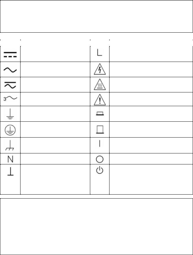
SAFETY SYMBOL DEFINITIONS
Symbol |
Description |
Symbol |
Description |
Direct current
Alternating current
Both direct and alternating current
Three-phase alternating current
Earth (ground) terminal
Protective earth (ground) terminal
Frame or chassis terminal
Terminal for Neutral conductor on permanently installed equipment
Terminal for Line conductor on permanently installed equipment
Caution, risk of electric shock
Caution, hot surface
Caution (refer to accompanying documents)
In position of a bi-stable push control
Out position of a bi-stable push control
On (supply)
Off (supply)
Terminal is at earth potential (Used for measurement and control
circuits designed to be operated with one terminal at earth potential.)
Standby (supply)
Units with this symbol are not completely disconnected from ac mains when this switch is off. To completely disconnect the unit from ac mains, either disconnect the power cord or have a qualified electrician install an external switch.
Herstellerbescheinigung
Diese Information steht im Zusammenhang mit den Anforderungen der
Maschinenläminformationsverordnung vom 18 Januar 1991.
* Schalldruckpegel Lp <70 dB(A) * Am Arbeitsplatz * Normaler Betrieb * Nach EN 27779 (Typprüfung).
Manufacturer’s Declaration
This statement is provided to comply with the requirements of the German Sound Emission Directive, from 18 January 1991.
* Sound Pressure Lp <70 dB(A) * At Operator Position * Normal Operation * According to EN 27779 (Type Test).
4

DECLARATION OF CONFORMITY
according to ISO/IEC Guide 22 and EN 45014
Manufacturer’s Name: |
Agilent Technologies |
Manufacturer’s Address: |
150 Green Pond Road |
|
Rockaway, New Jersey 07866 |
|
U.S.A. |
declares that the Product |
|
Product Name: |
a) Multiple-Output System Power Supply |
|
b) Precision Multiple-Output System Power Supply |
Model Number: |
a) Agilent 6621A, 6622A, 6623A, 6624A, 6627A |
|
b) Agilent 6625A, 6626A, 6628A, 6629A |
conforms to the following Product Specifications: |
|
Safety: |
IEC 348:1978 / HD 401S1: 19811 |
EMC: |
CISPR 11:1990 / EN 55011:1991 - Group 1 Class B |
|
IEC 801-2:1991 / EN 50082-1:1992 - 4 kV CD, 8 kV AD |
|
IEC 801-3:1984 / EN 50082-1:1992 - 3 V / m |
IEC 801-4:1988 / EN 50082-1:1992 - 0.5 kV Signal Lines
1 kV Power Lines
Supplementary Information:
The product herewith complies with the requirements of the Low Voltage Directive 73/23/EEC and the EMC Directive 89/336/EEC and carries the CE-marking accordingly.
Note 1: The product family was introduced prior to 12/93.
New Jersey |
January 1997 |
|
|
|
|
|
|
|
|||
Location |
Date |
Bruce Krueger / Quality Manager |
|||
European Contact: Your local Agilent Technologies Sales and Service Office or Agilent Technologies GmbH, Department TRE, Herrenberger Strasse 130, D-71034 Boeblingen (FAX:+49-7031-14-3143)
5
WHAT THIS MANUAL CONTAINS
This is the Operating manual for the Agilent 6621A through 6624A and 6627A Series of Multiple Output Linear System Power Supplies. It contains information relating to the installation, operation, and programming of these supplies as outlined below. Maintenance and troubleshooting instructions are given in a separate Service Manual (Agilent Part No. 5957-6379).
Chapter 1.--General Information
Chapter 1 contains a general description of the power supplies as well as instrument specifications and information concerning options and accessories.
Chapter 2.--Installation Procedures
Chapter 2 contains information to prepare the supply for use. Included in this chapter are power requirements, line voltage conversion, and GP-IB interface connections.
Chapter 3.--Getting Started
Chapter 3 contains a brief description of the supply’s front panel controls and indicators and describes how to turn on the supply and to check it’s operation. An introduction to remote operation over the GP-IB is also given to help a first time user get started quickly.
Chapter 4.--Output Connections and Operating Information
Chapter 4 contains information about making connections to the supply’s output terminals. General operating information is also provided.
Chapter 5.--Remote Operation
Chapter 5 contains all of the information required to operate the supply remotely via a GP-IB computer. All of the commands that can be used to program the supplies are described.
Chapter 6.--Local Operation
Chapter 6 contains instructions on using all of the front panel controls and indicators.
Appendix A--Calibration Procedure
Appendix A contains programming steps and procedures that are required to calibrate your power supply. It is recommended that the power supply be calibrated yearly.
Appendix B--Programming with Series 200 Computer
Appendix B contains Series 200/300 Computer programming examples (in Agilent extended BASIC language) for your Power Supply’s most frequently used functions.
Appendix C--Command Summary
Appendix C contains an alphabetical listing of all commands that can be sent to a supply.
Appendix D--Error Messages
Appendix D contains a listing and brief explanation of all error codes and messages for all programming and hardware errors.
Appendix E - Manual Backdating
Appendix E contains backdating information for units with Serial numbers lower than those listed on the title page.
6
|
Table Of Contents |
|
1 |
General Information |
|
|
Introduction............................ ....................................................................................................................... |
11 |
|
Safety Considerations.................................................................................................................................... |
11 |
|
Instrument and Manual Identification.... ....................................................................................................... |
11 |
|
Options................................. ......................................................................................................................... |
11 |
|
Accessories.................................................................................................................................................... |
12 |
|
Description ............................ ....................................................................................................................... |
12 |
|
Basic Operation......................... .................................................................................................................... |
13 |
|
GP-IB Board.............................................................................................................................................. |
13 |
|
Output Boards............................................................................................................................................ |
14 |
|
Specifications......................... ....................................................................................................................... |
15 |
|
Qualifying Conditions.................. ............................................................................................................. |
15 |
|
Definitions............................ ..................................................................................................................... |
15 |
2 |
Installation |
|
|
Introduction............................ ....................................................................................................................... |
25 |
|
Initial Inspection............................................................................................................................................ |
25 |
|
Location and Cooling.................... ................................................................................................................ |
25 |
|
Input Power Requirements................ ............................................................................................................ |
26 |
|
Line Fuse............................... ........................................................................................................................ |
26 |
|
Power Cord.................................................................................................................................................... |
28 |
|
Line Voltage Conversion............................................................................................................................... |
28 |
|
GP-IB Interface Connector............................................................................................................................ |
29 |
3 |
Getting Started |
|
|
Introduction ........................... ....................................................................................................................... |
31 |
|
Front Panel Controls and Indicators..... ......................................................................................................... |
31 |
|
Turning On Your Supply............................................................................................................................... |
31 |
|
Normal Self Test Indications..................................................................................................................... |
35 |
|
Self Test Errors.......................................................................................................................................... |
36 |
|
Checking Out Your Supply Using Local Control.......................................................................................... |
36 |
|
Voltage Test............................ .................................................................................................................. |
37 |
|
Overvoltage Test......................... .............................................................................................................. |
37 |
|
Current Test............................................................................................................................................... |
37 |
|
Introduction To Remote Operation....... ........................................................................................................ |
38 |
|
Enter/Output Statements............................................................................................................................ |
38 |
|
Reading the GP-IB Address.............. ........................................................................................................ |
39 |
|
Changing the GP-IB Address............. ....................................................................................................... |
39 |
|
Sending a Remote Command............... ..................................................................................................... |
39 |
|
Getting Data from the Supply.................................................................................................................... |
40 |
|
Often Used Commands.............................................................................................................................. |
40 |
|
Returning the Supply to Local Mode..... ................................................................................................... |
42 |
4 |
Output Connections and Operating Information |
|
|
Introduction ............................... ................................................................................................................... |
43 |
|
Output Ranges............................... ................................................................................................................ |
43 |
|
Operating Quadrants.................................................................................................................................. |
44 |
|
Range Selection............................. ............................................................................................................ |
44 |
|
Protection Features......................... ............................................................................................................... |
44 |
|
Connecting The Load......................... ........................................................................................................... |
46 |
|
Wire Size Selection......................... .......................................................................................................... |
47 |
|
Multiple Loads.............................. ............................................................................................................ |
49 |
7
|
Table Of Contents (continued) |
|
|
Positive and Negative Voltages................................................................................................................. |
49 |
|
Remote Voltage Sensing..................... .......................................................................................................... |
49 |
|
Remote Sense Connections................... .................................................................................................... |
50 |
|
Output Noise Considerations..................................................................................................................... |
51 |
|
Programming Response Time with an Output Capacitor............................. ............................................. |
51 |
|
Open Sense Leads...................................................................................................................................... |
51 |
|
Overvoltage Trigger Connections............ ..................................................................................................... |
52 |
|
External Trigger Circuit................... ......................................................................................................... |
52 |
|
Power Supply Protection Considerations .......................... ........................................................................... |
54 |
|
Battery Charging........................... ............................................................................................................ |
54 |
|
Capacitive Load Limitation....................................................................................................................... |
54 |
|
Parallel Operation.......................................................................................................................................... |
54 |
|
CV Operation............................... ............................................................................................................. |
55 |
|
CC Operation............................................................................................................................................. |
56 |
|
Remote Sensing........................... .............................................................................................................. |
56 |
|
Specifications for Parallel Operation......................................................................................................... |
56 |
|
Series Operation....................... ..................................................................................................................... |
57 |
|
CV Operation............................... ............................................................................................................. |
57 |
|
CC Operation............................................................................................................................................. |
58 |
|
Remote Sensing........................... .............................................................................................................. |
58 |
|
Specifications for Series Operation. .......................................................................................................... |
58 |
5 |
Remote Operation |
|
|
Introduction ............................. ..................................................................................................................... |
61 |
|
GP-IB Operation............................................................................................................................................ |
61 |
|
Interface Function...................................................................................................................................... |
61 |
|
GP-IB Address Selection........................................................................................................................... |
62 |
|
Power-On Service Request (PON) ............................................................................................................ |
63 |
|
Programming Syntax......................... ............................................................................................................ |
63 |
|
Numeric Data............................... ............................................................................................................. |
63 |
|
Order of Execution......................... ........................................................................................................... |
68 |
|
Terminators................................ ............................................................................................................... |
68 |
|
Initial Conditions........................................................................................................................................... |
68 |
|
Power Supply Commands ............................................................................................................................. |
68 |
|
Voltage Programming........................ ....................................................................................................... |
69 |
|
Current Programming.............................. .................................................................................................. |
69 |
|
Range Switching........................................................................................................................................ |
70 |
|
Output On/Off.................................... ....................................................................................................... |
71 |
|
Overvoltage Protection........................... ................................................................................................... |
71 |
|
Overcurrent Protection........................... ................................................................................................... |
72 |
|
Multiple Output Storage and Recall............... ........................................................................................... |
72 |
|
The Clear Command.................................................................................................................................. |
73 |
|
Status Reporting................................. ....................................................................................................... |
73 |
|
Service Request Generation....................... ............................................................................................... |
76 |
|
Reprogramming Delay............................. ................................................................................................. |
78 |
|
Display On/Off................................... ....................................................................................................... |
78 |
|
Other Queries............................................................................................................................................. |
79 |
6 |
Local Operation |
|
|
Introduction ..................................... ............................................................................................................. |
83 |
|
Local Mode.................................................................................................................................................... |
83 |
|
Local Control Of Output Functions............................................................................................................... |
83 |
|
General........................................... ............................................................................................................... |
83 |
8
|
Table Of Contents (continued) |
|
|
Setting Voltage................................. ......................................................................................................... |
84 |
|
Setting Current........................................................................................................................................... |
84 |
|
Enabling/Disabling an Output...................... ............................................................................................. |
85 |
|
Setting Overvoltage Protection.................................................................................................................. |
85 |
|
Resetting Overvoltage Protection.............................................................................................................. |
85 |
|
Enabling/Disabling Overcurrent Protection........ ...................................................................................... |
85 |
|
Resetting Overcurrent Protection................. ............................................................................................. |
85 |
|
Displaying the Contents of the Fault Register........................................................................................... |
85 |
|
Setting the Reprogramming Delay................ ............................................................................................ |
86 |
|
Local Control Of System Functions................ .............................................................................................. |
86 |
|
Setting the Supply’s GP-IB Address.......................................................................................................... |
86 |
|
Displaying Error Messages........................................................................................................................ |
87 |
|
Storing and Recalling Voltage and Current Settings for all Outputs......................................................... |
87 |
A |
Calibration |
|
|
Introduction...................................... ............................................................................................................. |
89 |
|
Test Equipment and Setup Required................. ............................................................................................ |
89 |
|
General Calibration Procedure..................... ................................................................................................. |
91 |
|
Calibration Program.............................. ........................................................................................................ |
93 |
B |
Programming With a Series 200/300 Computer |
|
|
Introduction ....................... ........................................................................................................................... |
97 |
|
I/O Path Names...................... ....................................................................................................................... |
97 |
|
Voltage and Current Programming..... .......................................................................................................... |
97 |
|
Voltage and Current Programming With Variables... ................................................................................... |
98 |
|
Voltage and Current Readback...................................................................................................................... |
98 |
|
Programming Power Supply Registers.......................................................................................................... |
99 |
|
Present Status...................... ...................................................................................................................... |
99 |
|
Service Request and Serial Poll................................................................................................................. |
99 |
|
Error Detection .................... ................................................................................................................... |
101 |
|
Stored Operating States........... ................................................................................................................ |
102 |
|
Programming Outputs Connected In Parallel.............................................................................................. |
102 |
|
CC Operation........................................................................................................................................... |
103 |
|
CV Operation....................... ................................................................................................................... |
103 |
|
Programming Outputs Connected In Series..... ........................................................................................... |
104 |
C |
Command Summary |
|
|
Introduction ................................................................................................................... .............................. |
105 |
D |
Error Messages |
|
|
Introduction....................... .......................................................................................................................... |
109 |
|
Power-On Self Test Messages..................................................................................................................... |
109 |
|
Error Responses........................................................................................................................................... |
109 |
|
Test Responses...................... ...................................................................................................................... |
109 |
E |
Manual Backdating |
|
|
Introduction ........................ ........................................................................................................................ |
113 |
|
Make Changes ....................... ..................................................................................................................... |
113 |
|
Addendum |
|
|
Generally Applicable Annotations/CE’92 Product Specific Annotations ........................ .......................... |
114 |
|
Agilent Sales and Support Office |
|
|
Contacts ...................................................................................................................................................... |
115 |
9

1
General Information
Introduction
This chapter contains a general description of your power supply, as well as its performance specifications. Information about options, accessories, and GP-IB cables is also provided. This manual describes all five models in the Agilent 6621A6624A, and 6627A power supply family. Unless stated otherwise, the information in this manual applies to all of these models. Information that is specific to one model only is identified as such in this manual.
Safety Considerations
This product is a Safety Class 1 instrument, which means that it is provided with a protective earth terminal. This terminal must be connected to a power source that has a 3-wire ground receptacle. Review the instrument and this manual for safety markings and instructions before operation. Refer to the Safety Summary page at the beginning of this manual for a summary of general safety information. Safety information for specific procedures is located at appropriate places in this manual.
Instrument and Manual Identification
Agilent Technologies power supplies are identified by a two-part serial number, i.e. 2601A-00101. The first part of the serial number (the prefix) is a number/letter combination that denotes either the date of manufacture or the date of a significant design change. It also indicates the country of origin. (Starting at 1960, 26 = 1986; 01 = the first week of the year; A = U.S.A.) The second part of the serial number is a different sequential number assigned to each instrument starting with 00101.
If the serial number prefix on your power supply differs from that shown on the title page of this manual, a yellow Manual Changes sheet that is supplied with this manual explains the difference between your instrument and the instrument described by this manual. The change sheet can also contain information for correcting errors in the manual.
Options
Options 100,120, 220, and 240 simply determine which line voltage is selected at the factory. For information about changing the line voltage setting, see Line Voltage Conversion, page 28.
Option 750 consists of a fault indicator (FLT) and remote inhibit (INH) circuit and relay control, which provide additional shutdown protection should either the GP-IB and/or controller fail. This Option is described in a separate document entitled, "Appendix E Option 750 Operating Instructions for the Multiple Output Linear System DC Power Supply, Agilent Models 6621A, 6622A, 6623A, 6624A, and 6627A (Agilent P/N 5957-6372).
#100 Input power, 100 Vac, 47--66 Hz #120 Input power, 120 Vac, 47--66 Hz #220 Input power, 220 Vac, 47--66 Hz #240 Input power, 240 Vac, 47--66 Hz
#700 Computer Interface Intermediate Language (CIIL) #750 Fault (FLT) Remote Inhibit (INH) and Relay Control #908 One rack mount kit (5062-3977)
#909 One rack mount kit with handles (5062-3983) #910 One service manual with extra operating manual
General Information 11
Accessories
10833A GP-IB cable, 1 m (3.3 ft)
10833B GP-IB cable, 2 m (6.6 ft)
10833C GP-IB cable, 4 m (13.2 ft)
10833D GP-IB cable, 0.5 m (1.6 ft)
10834A GP-IB connector extender Slide mount kit (1494-0059)
Description
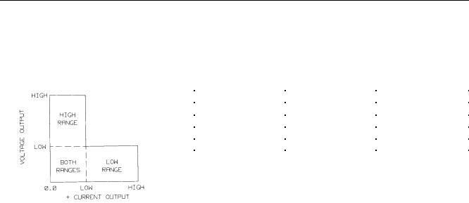
The Agilent 6621A-6624A, and 6627A Multiple Output Linear Power Supplies feature a combination of programming capabilities and linear power supply performance that make systems applications. The five models in this family offer a total of up to 200 watts of output power, with voltages up to 50 volts and currents up to 10 amps. The output combinations that correspond to each model are shown in Table 1-1. Each isolated output can supply power in two ranges as shown in Figure 1-1. This flexibility allows you to use the same output to power loads with different voltage and current requirements. No separate command is required to program ranges; the power supply automatically selects one of the operating ranges based on the last parameter (voltage or current) that is set. Additionally, each output contains an active downprogrammer, which means that voltage downprogramming can be accomplished as quickly as upprogramming, even without a load.
|
|
Table 1-1. Output Combinations Available |
|
|||
Model |
|
Output 1 |
|
Output 2 |
Output 3 |
Output 4 |
Agilent 6621A |
80 |
W Low Voltage |
80 |
W Low Voltage |
- |
- |
Agilent 6622A |
80 |
W High Voltage |
80 |
W High Voltage |
- |
- |
Agilent 6623A |
40 |
W Low Voltage |
80 |
W Low Voltage |
40 W High Voltage |
- |
Agilent 6624A |
40 |
W Low Voltage |
40 |
W Low Voltage |
40 W High Voltage |
40 W High Voltage |
Agilent 6627A |
40 |
W High Voltage |
40 |
W High Voltage |
40 W High Voltage |
40 W High Voltage |
The output voltage and current for any output can be monitored with the front panel display. Output specific error messages are also displayed. Front panel annunciators show the operating status of the instrument. The front panel keypad lets you set and readback the voltage limit, current limit, and overvoltage trip level of any output. With the keypad, you can also enable or disable outputs, mask and delay bits in the fault register, enable overcurrent protection, reset overvoltage and overcurrent protection, and return to local operating mode.
Your multiple output power supply can be both a listener and a talker on the GP-IB. (GP-IB is Agilent Technologies’s implementation of IEEE-488). The built-in interface is tailored to the supply, resulting in simpler programming. Voltage and current settings can be sent directly to the specified dual range output in volts and amps.
Service can be requested from your power supply for up to ten reasons. The supply responds to a serial poll by identifying the output on which the fault occurred. Self-contained measurement and readback capability eliminate the need for externally scanning the outputs using a separate DVM. Upon command the supply will measure its output voltage or current and return the value on the GP-IB. The following functions are implemented via the GP-IB:
Voltage and current programming.
Voltage and current measurement and readback.
Present and accumulated status readback.
Programmable service request mask.
Programmable overvoltage and overcurrent protection.
Storage and recall of programmed voltage and current values for all outputs.
Queries of programmed functions or settings.
Output enable or disable.
Programming syntax error detection.
12 General Information
Programmable delay time for service request and OCP mask.
Voltage, current, and overvoltage calibration.
GP-IB interface selftest.
Message display capability on the front panel.
Output connections are made to rear panel screw terminals. Either the positive or negative output terminal can be grounded, or the output can be floated up to ± 240 Vdc (including output voltage) from chassis ground. Output voltage can be locally or remotely sensed, and identical outputs can be operated in series or parallel combinations for increased output voltage or current capability. As shipped from the factory, the power supply is jumpered for local sensing.
Your power supply can be calibrated without having to remove the cover or even having to remove it from your system cabinet. This feature allows you to calibrate the supply at its normal operating temperature. The recommended calibration interval is one year. Refer to Appendix A of this manual for complete calibration details. A calibration security jumper is available inside the unit. Access is described in the service manual.
Basic Operation
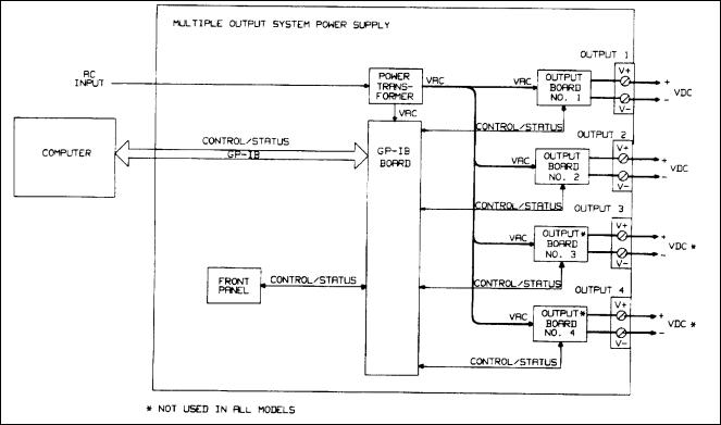
Figure 1-2 is a block diagram that illustrates the major assemblies contained within the power supply. As shown in the figure, each supply includes a power transformer, two or more output boards, a GP-IB board, and front panel (display and control keys).
Output |
Low Range Values |
High Range Values |
80 W Low, Voltage |
7 V @ 10 A |
20 V @ 4 A |
80 W High Voltage |
20 V @ 4 A |
50 V @ 2 A |
40 W Low Voltage |
7 V @ 5 A |
20 V @ 2 A |
40 W High Voltage |
20 V @ 2 A |
50 V @ 0.8 A |
Figure 1-1. Output Operating Ranges for Agilent Models 6621A, 6624A and 6627A.
The appropriate ac input voltage is applied to each output board where it is converted to a raw dc voltage which is subsequently linearly regulated to become the dc output voltage. The magnitude of the output and the mode of operation are determined by the load and the data received from the GP-IB computer or from the front panel.
Each power supply model contains one output board for each output that it provides. Models 6624A and 6627A contain four 40 watt output boards; Model 6623A contains two 40 watt output boards and one 80 watt output board; Models 6621A and 6622A each contain two 80 watt output boards.
GP-IB Board
The GP-IB board provides the interface between the user and the multiple outputs of the power supply. Each output board is actually an output channel that can be individually selected and controlled over the GP-IB or from the supply’s front panel. Circuits on the GP-IB board interpret commands from the GP-IB or from the front panel to control the selected output.
The GP-IB board also processes measurement and status data received from the output boards. This data may be read back over the GP-IB and/or displayed on the supply’s front panel.
General Information 13
The power supply has no potentiometers. Each output is individually calibrated over the GP-IB using calibration commands (see Appendix A). Correction factors are calculated by the power supply during calibration and are stored in a non-volatile memory which is located on the supply’s GP-IB board. The supply contains no batteries.
Output Boards
The output boards are linear dc power supplies. Each isolated output has the L-shaped operating curve described in Description, page 12 and Figure 1-1.
The ac input to each output board is rectified and applied to a regulator circuit. Each output board employs series regulation techniques. A regulator element is connected in series with the load and operates in the linear region (between saturation and cutoff) of the transistor characteristic curve. Regulation is achieved by varying the conduction of the series element in response to a change in line voltage or circuit load.
The output board receives digital signals from the GP-IB board and converts them to analog signals which program the output voltage, current, and overvoltage values. The output may be programmed remotely over the GP-IB using commands (see Chapter 5) or locally from the supply’s front panel using the control keys (see Chapter 6).
The output board can be commanded to send measurement and status data back over the GP-IB and/or front panel. The data is sent back via the supply’s GP-IB board. GP-IB readback capabilities include output voltage and current, present and accumulated status, and all programmed settings. The front panel LCD display can indicate the output voltage and current, the supply’s GP-IB address, error messages, and programmed values. Annunciators on the front panel indicate the operating status of the selected channel (output board).
Figure 1-2. Agilent 6621A, 6624A and 6627A Multiple Output System Power Supplies, Block Diagram
14 General Information

Specifications
Table 1-2 lists the performance specifications for the Agilent 662xA power supplies. Performance specifications describe the instrument’s warranted performance. The service manual, Option 9l0, contains procedures for verifying the performance specifications.
Table 1-3 lists the supplemental characteristics for the Agilent 662xA supplies. Supplemental characteristics are type-tested or typical values, which are based on a product sample and, while representative, are not guaranteed.
Qualifying Conditions
All performance specifications apply over the full operating temperature range of the power supply (0 to 55°C) unless otherwise specified. All regulation, accuracy, etc. specifications are plus or minus the values listed. All measurements are made at the rear terminals of the supply with a resistive load and local sensing unless otherwise specified. Voltage measurements are made from the + S to the - S terminals. Overvoltage measurements are made from the + V to the - V terminals. + Current refers to the output acting as a current source while - Current refers to the output acting as a current sink.
Definitions
Load effect: Maximum steady state change in the regulated output parameter due to a change in load resistance on the output in question.
Source effect: Maximum steady state change in the regulated output parameter due to a change in the source voltage within rated values. (Expressed as a percentage of setting plus a constant).
Cross regulation: Maximum steady state change in the regulated output parameter due to a change in load resistance on any other output(s).
Programming accuracy: (Calibration temp ± 5°C) Maximum difference between the programmed value and the actual output. (Expressed as a constant plus a percentage of the setting.)
Readback accuracy: (Calibration temp ± 5°C) Maximum error in reading back an output parameter. (Expressed as a constant plus a percentage of the reading).
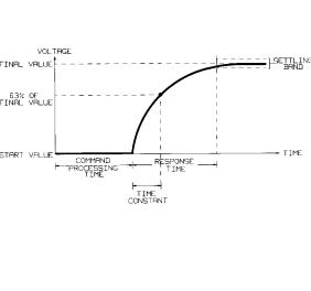
Output response time: Beginning at the time the power supply has finished processing a VSET command (change output voltage), the maximum time for the output voltage to settle to within a settling band about the final value from any specified operating point. This value must be added to the command processing time to obtain total programming time (see Figure 1-3). Time constant is the maximum time required for the voltage to reach 63% of its final value.
Temperature coefficient: Maximum change in the regulated output parameter per °C change in ambient temperature after a 30 minute warmup. Expressed in parts-per-million plus a constant per °C (plus a constant for readback temperature coefficient).
Long Term Drift: Maximum change of regulated output voltage or current during an 8-hour period following a 30 minute warmup, with all influence and control quantities maintained constant. Expressed as a percentage of setting plus a constant.
Short Term Drift: Maximum change of regulated output voltage or current within 30 minutes after a line and/or load change. Expressed as a percentage of setting plus a constant.
Output Noise (PARD): PARD replaces the former term ripple and noise. PARD is the periodic and random deviation of dc output voltage or current from its average value, over a specified bandwidth and with all influence and control quantities maintained constant.
General Information 15
Programming resolution: Average programming step size.
Current Sinking ( - Current): Each output can sink as well as source current. The sinking capability is not programmable and depends upon the output voltage. The current sinking capability is described in greater detail in Chapter 4.
Figure 1-3. Output Response Characteristics
16 General Information

Table 1-2. Specifications
PERFORMANCE SPECIFICATIONS (0 to 55°C unless otherwise specified) |
|
|
||
Outputs: |
40 W Low |
40 W High |
80 W Low |
80 W High |
|
Voltage |
Voltage |
Voltage |
Voltage |
DC Output Ranges: All outputs will accept voltage programming commands 1% higher than those listed and current programming commands 3% higher than those listed. Also, the minimum programmable current values are slightly above zero amps for each output. (See Table 5-4).
Low Range |
0-7 V; 0-5 A |
0-20 V; 0-2 A |
0-7 V; 0-10 A |
0-20 V: 0-4 A |
High Range |
0-20 V; 0-2 A |
0-50 V: 0-0.8 A |
0-20 V; 0-4 A |
0-50 V; 0-2 A |
Load Effect (Regulation): When remote sensing, add 1 mV to the value listed for each 200 mV drop in the - V load lead.
Voltage |
2 mV |
2 mV |
2 mV |
2 mV |
+ Current |
1 mA |
0.5 mA |
2 mA |
1 mA |
Source Effect: |
|
|
|
|
Voltage |
0.01% + 1 mV |
0.01% + 1 mV |
0.01% + 1 mV |
0.01% + 1 mV |
+ Current |
0.06% + 1 mA |
0.06% + 1 mA |
0.06% + 2 mA |
0.06% + 2 mA |
Programming Accuracy: (At calibration temperature ± 5°C)
Note: The programming accuracy specifications may degrade slightly when the unit is subjected to an RF field equal to or greater than 3 volts/meter.
Voltage |
19 mV + 0.06% |
50 mV + 0.06% |
19 mV + 0.06% |
50 mV + 0.06% |
+ Current |
100 mA + 0.16% |
20 mA + 0.16% |
100 mA + 0.16% |
40 mA + 0.16% |
OVP |
200 mV + 0.13% |
475 mV + 0.13% |
200 mV + 0.13% |
475 mV + 0.13% |
Readback Accuracy: (At calibration temperature ±5°C)
Voltage |
20 mV + 0.05% |
50 mV +0.05% |
20 mV + 0.05% |
50 mV +0.05% |
+ Current |
10 mA +0.1% |
4 mA + 0.1% |
20 mA +0.1% |
8 mA +0.1% |
- Current |
25 mA +0.2% |
8 mA +0.2% |
50 mA +0.2% |
20 mA +0.2% |
Load Transient Recovery Time:
75 μS maximum to recover to within 75 mV of nominal value following a load change within the range 300 mA to full load for low voltage units, and 150 mA to full load for high voltage units.
Maximum Output Noise (PARD):
CV peak-to-peak |
3 mV |
3 mV |
3 mV |
3 mV |
(20 Hz--20 MHz) |
|
|
|
|
CV rms |
0.5 mV |
0.5 mV |
0.5 mV |
0.5 mV |
(20 Hz--10 MHz) |
|
|
|
|
+ CC rms |
1 mA |
1 mA |
2 mA |
2 mA |
(20Hz--10 MHz) |
|
|
|
|
AC Input Voltage and Frequency:
Nominal Line = 100,120, 220, or 240 Vac
Amplitude = + 6%, -13% of nominal line voltage
Frequency Range = 47-66 Hz
Note: At low line, the supply will operate with up to 3/4 Ω line resistance.
General Information 17

Table 1-3. Supplemental Characteristics
Outputs |
40 W Low |
40 W High |
80 W Low |
|
80 W High |
|
Voltage |
Voltage |
Voltage |
|
Voltage |
Temperature Coefficient: |
|
|
|
|
|
Voltage |
(60 ppm + 0.4 mV)/ °C |
(60 ppm + 1 mV)/ °C |
(60 ppm + 0.4 mV)/ °C |
(60 ppm + 1 mV)/ °C |
|
+Current |
(160 ppm +0.2mA)/°C |
(160 ppm +0.1 mA)/°C |
(160 ppm +0.4mA)/°C |
(160 ppm +0.2 mA)/°C |
|
OVP |
(130 ppm + 1 mV)/ °C |
(130 ppm + 2 mV)/ °C |
(130 ppm + 1 mV)/ °C |
(130 ppm + 2 mV)/ °C |
|
Readback Temperature Coefficient: |
|
|
|
|
|
Voltage |
(40 ppm +0.3 mV)/°C |
(40 ppm +0.7 mV)/°C |
(40 ppm +0.3 mV)/°C |
(40 ppm +0.7 mV)/°C |
|
|
+ 10 mV |
+ 23 mV |
+ 10 mV |
|
+ 23 mV |
+Current |
(85 ppm +0.25 mA)/°C |
(85 ppm +0.1 mA)/°C |
(85 ppm +0.5 mA)/°C |
(85 ppm +0.2 mA)/°C |
|
|
+3 mA |
+1 mA |
+5 mA |
|
+2 mA |
-Current |
(95 ppm + 0.3 mA)/°C |
(95 ppm +0.1 mA)/°C |
(95 ppm +0.6 mA)/°C |
(95 ppm +0.2 mA)/°C |
|
|
+3 mA |
+1.2 mA |
+6 mA |
|
+2.3 mA |
Long Term Drift: (In an 8 hour period following a 30 minute warmup): |
|
|
|
||
Voltage |
0.012% + 1 mV |
0.012% + 1 mV |
0.012% + 1 mV |
0.012% + 1 mV |
|
+ Current |
0.032% + 2 mA |
0.032% + 2 mA |
0.032% + 4 mA |
0.032% + 4 mA |
|
Short Term Drift: (Within 30 minutes after a line and/or load change): |
|
|
|
||
Voltage |
0.042% + 2 mV |
0.042% + 2 mV |
0.042% + 2 mV |
0.042% + 2 mV |
|
+Current |
0.11%+4 mA |
0.11%+4 mA |
0.11%+8 mA |
0.11%+8 mA |
|
Programmable OVP Ranges: |
|
|
|
|
|
|
0-23 V |
0-55 V |
0-23 V |
0-55 V |
|
Load Cross Regulation: |
|
|
|
|
|
Voltage |
1 mV |
2.5 mV |
1 mV |
2.5 mV |
|
+Current |
1 mA |
0.5 mA |
2 mA |
1 mA |
|
Output Response Characteristics: (See Figure 1-3) |
|
|
|
|
|
Max Output |
2 ms |
6 ms |
2 ms |
6 ms |
|
Programming |
|
|
|
|
|
Response Time |
|
|
|
|
|
Settling Band |
20 mV |
50 mV |
20 mV |
50 mV |
|
Max Time Constant |
250 μS |
750 μS |
250 μS |
750 μS |
|
DC Floating Voltage:
No output terminal may be more than 240 Vdc from any other terminal or from chassis ground. Also, no overvoltage terminal may be more than 240 Vdc from any other terminal or chassis ground.
Remote Sense Capability: (See wire size selection, page 47 and remote voltage sensing, page 48)
Outputs can maintain specifications with up to 1 volt drop per load lead except that the maximum voltage at the output terminals must not exceed the rated output voltage + 1 volt (see Figure 4-6). If the steady state voltage drop exceeds approximately 1.5 V on either load lead when remote sensing, a circuit will trip the OVP.
18 General Information

|
Table 1-3. Supplemental Characteristics (continued) |
|
||||
Outputs |
40 W Low |
40 W High |
80 W Low |
|
80 W High |
|
|
Voltage |
Voltage |
Voltage |
Voltage |
||
Programming Resolution: |
|
|
|
|
|
|
|
|
|
|
|
||
|
|
|
|
|
||
Voltage |
6 mV |
15 mV |
6 mV |
15 mV |
||
+Current |
25 mA |
10 mA |
50 mA |
20 mA |
||
OVP |
100 mV |
250 mV |
100 mV |
250 mV |
||
Readback Resolution: |
|
|
|
|
|
|
|
|
|
|
|
||
Voltage |
6 mV |
15 mV |
6 mV |
15 mV |
||
+ or-Current |
2 mA |
0.8 mA |
4 mA |
1.6 mA |
||
Fixed Overvoltage Protection: (Measure at output terminals +V and -V): |
|
|||||
|
|
|
|
|
||
Minimum |
22.5 V |
56 V |
22.5 V |
56 V |
||
Nominal |
24 V |
60 V |
24 V |
60 V |
||
Maximum |
26 V |
64 V |
26 V |
64 V |
||
AC Input Power and Current: |
|
|
|
|
||
|
|
|
|
|
||
Maximum Power = 550 W |
100 V Option |
120 V Option |
220 V Option |
240 V Option |
||
High Line Inrush Current |
85 A |
85 A |
50 A |
50 A |
||
(pk) |
|
|
|
|
|
|
High Line Input Current |
6.3 A |
5.7 A |
3.0 A |
3.0 A |
||
(rms) |
|
|
|
|
|
|
Fuse Rating |
8 A |
8 A |
4 A |
4 A |
||
GP-IB Interface Capabilities:
SH1, AH1, T6, L4, SR1, RL1, PP1, DC1, DT0, C0, E1
Current Sink Capability:
Current sink limits are fixed approximately 10% higher than the maximum current source limits for a given operating voltage at any voltage above 2.5 V (see Chapter 4).
Command Processing Time: (see Figure 1-3):
7 milliseconds typical (with front panel display disabled). Using STO and RCL commands allows you to change all the voltage and current settings in about 10 mS (with front panel display disabled).
Series and Parallel Operation:
Two outputs can be operated directly in parallel or can be connected for straight series operation. Refer to Chapter 4 for more information.
Reactive Load Capability:
All outputs have been designed with the ability to operate with significant reactive loads without instability (refer to Figures 1-4 through 1-6).
General Information 19

Table 1-3. Supplemental Characteristics (continued)
Output Impedance:
Approximated by a resistance in parallel with an inductance (see graphs in Figure 1-7). The values for each output are:
40 W Low Voltage |
40 W High Voltage |
80 W Low Voltage |
80 W High Voltage |
|
0.15Ω, 2.0μH |
0.3 Ω, 5 μH |
0.15 Ω, 0.8 μH |
0.5 Ω, 3 μH |
|
|
|
|
|
Safety Agency Compliance:
This series of power supplies is designed to comply with the following standards: IEC 348, UL 1244, and CSA 22.2 No. 231.
Dimensions: (all models)
Height = 132.6 mm (5.22in.)
Width = 425.5 mm (16.75in.)
Depth = 497.8 mm (19.6in.)
Weight: (all models):
Net Weight = 17.4 kg (38 lb.)
Shipping Weight = 22.7 kg (50 lb.)
20 General Information
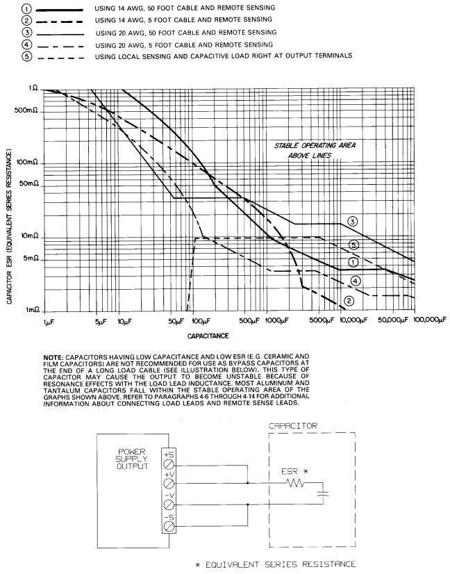
Figure 1-4. CV Operation with Capacitive Load, Stability Graph for all Outputs
General Information 21

Figure 1-5. CC Operation with Inductive Load, Small Signal Stability Graph for HV (0 to 50 V) Outputs
22 General Information
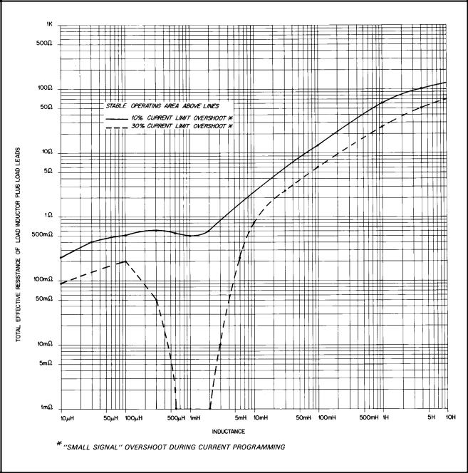
Figure 1-6. CC Operation with Inductive Load, Small Signal Stability Graph for LV (0 to 20 V) Outputs
General Information 23
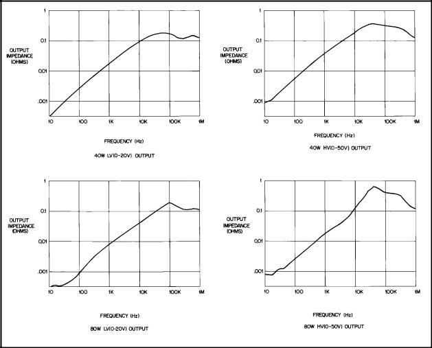
Figure 1-7. Output Impedance (Typical) Graphs (See Supplemental Characteristics, Table 1-1)
24 General Information

2
Installation
Introduction
This chapter contains instructions for checking and mounting your power supply, connecting your supply to ac power, converting it from one line voltage to another, and connecting the GP-IB cable.
The power supply generates operating magnetic fields which may affect the operation of other instruments. If your instrument is susceptible to magnetic fields, do not locate it in the immediate vicinity of the power supply. Typically, at three inches from the power supply, the electromagnetic field is less than 5 gauss.
NOTE |
The Agilent 662xA power supplies generate operating magnetic fields which may affect the operation of |
|
other instruments. If your instrument is susceptible to operating magnetic fields, position it more than 3 |
|
inches from the Agilent 662xA supply. |
Initial Inspection
Your instrument was thoroughly inspected and tested before it left the factory. As soon as you receive it, remove the power supply from its packing case and check to make sure it has not been damaged in shipment. Check that there are no broken connectors or keys, and that the cabinet and panel surfaces are free from dents and scratches. Check the rear panel terminal blocks and front panel display for any cracks. If damage is found, you should file a claim with the carrier immediately and notify the Agilent Technologies Sales and Service office nearest you.
Chapter 3 of this manual includes an electrical turn-on check-out procedure which, when carried out successfully, will give you a high level of confidence that the power supply is operating in accordance with its specifications. Detailed electrical checks complete with verification procedures are included in the Service Manual.
Keep the original packing materials for the carrier’ s inspection if there was damage, or in case any equipment has to be returned to Agilent Technologies. Warranty information is printed on the inside cover of this manual. Remember to send a detailed description of the failure and symptoms when returning the power supply for service. Your Agilent Technologies Sales and Service office will furnish the address of the nearest service office to which the instrument can be shipped .
Location and Cooling
Your power supply can operate without loss of performance within the temperature range of 0 to 55 ° C (measured at the fan intake). The fan, located at the rear of the unit, cools the supply by drawing air in through the openings on the rear panel and exhausting it through openings on the sides. Using Agilent Technologies rack mount kits will not impede the flow of air.
Because the power supply is fan cooled, it must be installed in a location that allows sufficient space at the rear and the sides for adequate circulation of air. Either side may be restricted to have as little as 1 inch (25 mm) space.
Figure 2-1 gives the dimensions of the power supply cabinet. These dimensions apply to all five models. The cabinet has plastic feet that are shaped to ensure self-alignment when stacked with other Agilent Technologies System II cabinets. The feet may be removed for rack mounting.
The power supply can be mounted in a standard 19 inch rack panel or enclosure. Rack mounting accessories for this unit are listed on page 12, under Options of Chapter 1. Complete installation instructions are included with each rack mounting kit. Instrument support rails are required for non-stationary installations. These are normally supplied with the cabinet and are not included with the rack mounting kits.
Installation 25
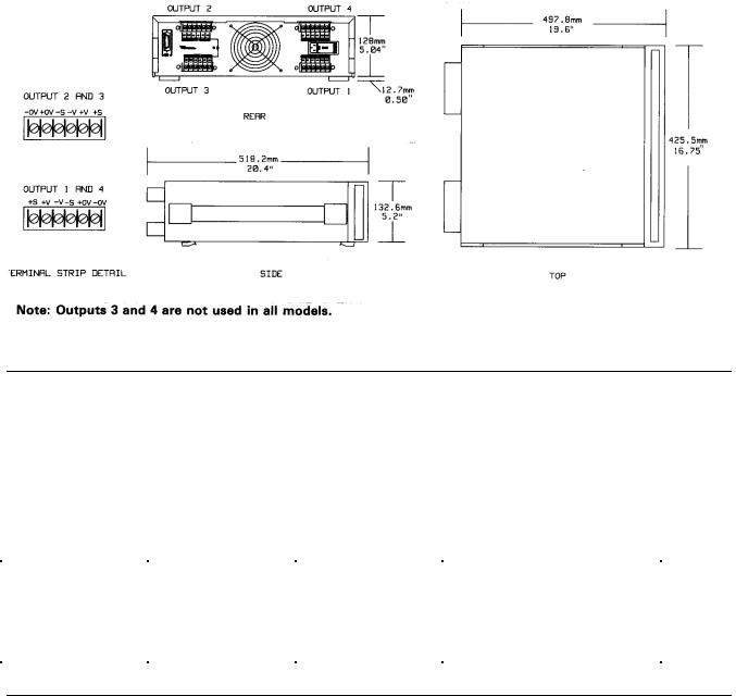
Figure 2-1. Outline Diagram
Input Power Requirements
You can operate this power supply from a nominal 100 V, 120 V, 220 V or 240 V single phase power source at 47 to 66 Hz. The input voltage range, maximum input current, high line inrush current (PK), and the fuse required for each of the nominal inputs are listed in Table 2-1. You can check the line voltage setting of your supply by examining the door on the line module. This is located on the rear panel of your supply as shown in Figure 2-2.
If necessary, you can convert the supply from one line voltage setting to another by following the instructions under Line Voltage Conversion (page 28).
|
|
Table 2-1. Input Power |
|
|
||
Nominal Voltage |
Line Voltage |
|
Maximum Input |
|
High Line Inrush Current |
Fuse |
|
Range |
|
Current (rms) |
(PK) |
|
|
100 V |
|
|
6.3 A |
85 A |
8 AM |
|
120 V |
Nominal |
|
5.7 A |
85 A |
8 AM |
|
220 V |
-13%, +6% |
|
3.0 A |
50 A |
4 AM |
|
240 V |
|
|
3.0 A |
50 A |
4 AM |
|
Line Fuse
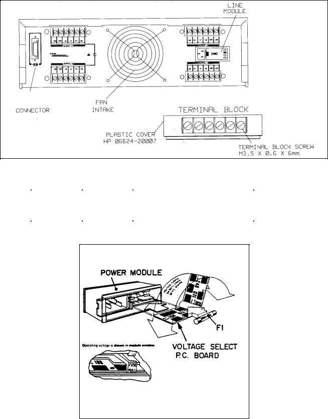
The ac line fuse is located behind the door on the line module (see Figure 2-3). To access the fuse, remove the power cord and push against the tab on the line module in the direction of the ac input socket. The current rating of the fuse is based on the line voltage setting of your supply. Table 2-2 gives the Agilent part numbers for the fuses that should be used with specific line voltages.
26 Installation
GP-IB
|
Figure 2-2. Rear Panel Detail (6624A Shown) |
||
|
|
Table 2-2 Line Fuses |
|
Line Voltage |
Fuse Needed |
|
Agilent Part Number |
|
|
|
(for 1/4 X 1-1/4 in. fuses only) |
100/120 V |
8AM |
2110-0342 |
|
220/240 V |
4AM |
2110-0055 |
|
Note All fuses are rated for 250 V.
Figure 2-3. Line Module Detail
Installation 27
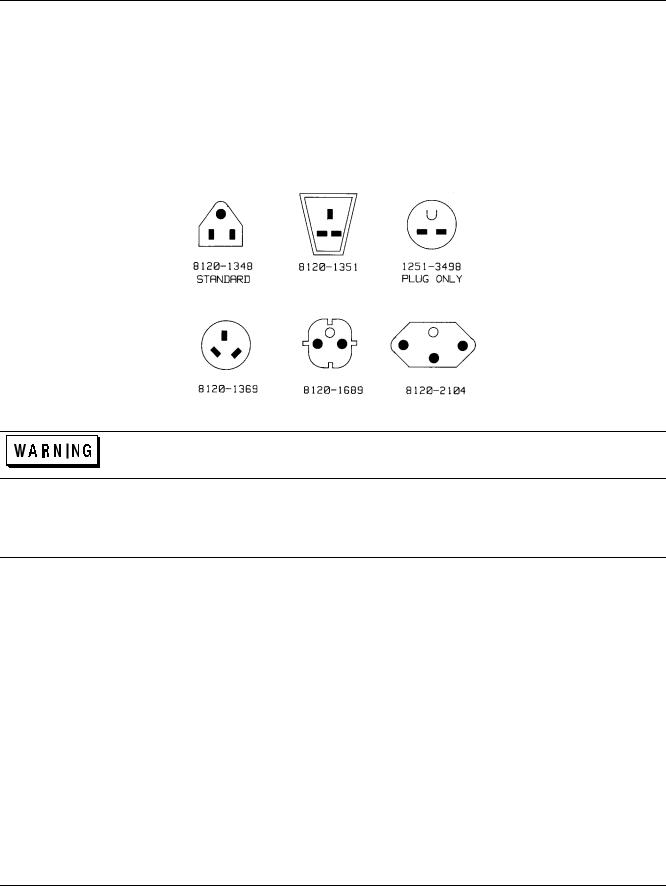
Power Cord
The power supply is shipped from the factory with a power cord that has a plug appropriate for your location. Figure 2-4 shows the standard configuration of plugs used by Agilent Technologies. Below each drawing is the Agilent part number for the replacement power cord equipped with a plug of that configuration. If a different power cord is required, contact the nearest Agilent Technologies Sales and Service office.
For your protection, the National Electrical Manufacturer’s Association (NEMA) recommends that the instrument panel and cabinet be grounded. This power supply is equipped with a three-conductor power cord; the third conductor being the ground. The power supply is grounded only when the power cord is plugged into an appropriate receptacle. Do not operate this power supply without adequate cabinet ground connection.
Figure 2-4. Power Cord Plug Configurations
SHOCK HAZARD Connect the power cord to a grounded receptacle before you connect any external floating voltages to the supply.
The offset pin on the standard three-prong power cord connector is the ground connection. If a two contact receptacle is encountered, it must be replaced with a properly grounded three-contact receptacle in accordance with the National Electrical Code, local codes and ordinances. The work should be done by a qualified electrician.
Line Voltage Conversion
You can change the supply to accept 100 V, 120 V, 220 V and 240 V ac input by adjusting the voltage selector card located inside of the line module (see Figure 2-3). After you have changed the line voltage, refer to Table 2-2 and check that the fuse inside the line module is the correct fuse for that line voltage. The procedure is as follows:
l. Turn off power and remove the power cord from the ac input socket on the back of the power supply.
2.To open the line module, move the plastic door on the module aside. If your line voltage change requires a change in the rating of the fuse, rotate FUSE PULL to the left and remove the fuse.
3.Grasp the voltage select pc board with a pair of needle-nose pliers and slide it out of its slot.
4.To select a voltage, orient the pc board so that the desired voltage appears on the top left side of the board. Push the board all the way back into its slot. The desired line voltage must be visible when the board is installed.
5.Install the correct fuse in the door of the line module if your line voltage change also requires a change in the rating of the fuse (see Table 2-2).
28 Installation

FIRE HAZARD Make sure the replacement fuse is one of the same type (size) and rating (amps) that is consistent with the voltage level you are operating at. Do not use a substitute fuse; use a fuse
with the same Agilent Part number listed in Table 2-2.
6. Close the door of the line module and insert the power cord in the ac input socket. Your power supply is now configured to operate at the voltage you selected.
GP-IB Interface Connector
The GP-IB connector on the rear panel connects your power supply to your computer and other GP-IB devices (see Figure 2-2). Chapter 1, page 12 lists the cables and cable accessories that are available from Agilent Technologies. An GP-IB system can be connected together in any configuration (star, linear, or both) as long as the following rules are observed:
1.The total number of devices, including the computer, is no more than 15.
2.The total length of all the cables used is no more than two meters times the number of devices connected together, up to a maximum of 20 meters.
NOTE |
IEEE Std. 488-1978 states that you should exercise caution if your individual cable lengths exceed 4m. |
Do not stack more than three connector blocks together on any GP-IB connector. The resultant leverage can exert excessive force on the mounting panels. Make sure that all connectors are fully seated and that the lock screws are firmly finger tightened. Do not use a screwdriver. Use a screwdriver only for the removal of the screws.
Installation 29

3
Getting Started
Introduction
This chapter is intended for the first time user of the supply. It provides four main discussions:
∙Front Panel Controls and Indicators
∙Turning on Your Supply
∙Checking Out Your Supply Using Local Control
∙Introduction to Remote Operation
First, the supply’s front panel controls and indicators are briefly described. Some of the controls and indicators will be used in the Turn On and Checkout procedures that follow. Chapter 6 describes how to use all of the front panel controls.
Successful completion of the turn on and checkout procedures ensures with a high level of confidence that your supply is operating properly. Complete performance testing and troubleshooting procedures are given in the Service Manual (Agilent Part No. 5957-6379).
The checkout procedures are performed locally from the front panel. In addition to checking the operation of your supply, these simple step-by-step checkout procedures will help the first time user become familiar with operating the supply from the front panel.
When you have completed the checkout procedures, you are then introduced to the fundamentals of operating the supply remotely from a computer. You will learn how to send a command to the supply from the computer and how to get data back to the computer from the power supply. A few of the most often used power supply commands will be described to help you get started and become familiar with the basics of programming your supply.
After completing this chapter, you can proceed to Chapter 4 to find out how to make load connections to your supply’s outputs and then to Chapter 5 (Remote Control) and/or Chapter 6 (Local Control) to learn all the details about operating your supply.
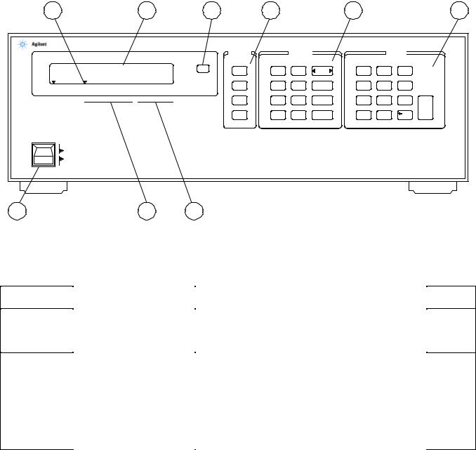
Front Panel Controls and Indicators
The power supply’s controls and indicators are shown in Figure 3-1 and are described in Table 3-1. Note that the front panel controls are identical for Agilent Models 6621A-6624A, and 6627A, except for the number of OUTPUT annunciators (number 3 in Figure 3-1). The Agilent Model 6624A, shown in Figure 3-1, has four outputs (as does the Agilent 6627A), Agilent Models 6621A and 6622A each have two outputs, and Agilent Model 6623A has three outputs.
Table 3-1, in addition to providing a brief description of each control and indicator, lists the paragraphs in which the use of each control and indicator is described. Because most of the functions performed by the front panel controls can also be performed remotely by power supply commands, the corresponding paragraphs in Chapter 5 (Remote Operation) are listed in Table 3-1 where applicable.
Turning On Your Supply
The following paragraphs describe the power-on sequence which includes a self test of most of the power supply’s circuits.
Before you turn on your supply, make sure that:
∙The line module on the rear panel is set to match your input line voltage.
∙The proper fuse is installed and the line cord is plugged in.
Getting Started 31
If you have any questions concerning installation or power requirements, review Chapter 2.
To turn on your supply, press the front panel LINE switch. When the power is initially applied, the supply performs a series of self tests which last about 3 seconds. Included in these tests are checks of circuits on the GP-IB board and on each of the output boards.
3 |
|
|
|
5 |
|
|
1 |
6 |
|
7 |
|
|
|
8 |
6624A SYSTEM DC POWER SUPPLY |
|
|
|
|
|
|
|
|
|
|
||||
|
|
|
|
|
|
|
SYSTEM |
|
OUTPUT |
|
|
|
ENTRY |
|
5.15V |
|
2.35A |
LCL |
ADDR |
METER |
OV |
OUTPUT |
7 |
8 |
9 |
|
|||
|
|
|
|
SET |
SELECT |
|
|
|
|
|||||
|
|
ERR |
DLY |
OV |
VSET |
4 |
5 |
6 |
|
|||||
1 2 |
3 4 |
CV CC |
UNR OCP |
ERR RMT ADDR |
SRQ |
|
|
|||||||
|
|
|
RST |
|
|
|
|
|
||||||
-- OUTPUT -- |
|
ENBLD |
|
|
|
|
|
|
|
|
|
|
||
|
|
|
|
|
|
|
|
|
|
|
|
|||
|
|
|
|
|
|
|
STO |
UN |
OCP |
ISET |
1 |
2 |
3 |
ENTER |
|
|
|
|
|
|
|
|
MASK |
|
|
|
|
|
|
|
|
|
|
|
|
|
RCL |
FAULT |
OC |
OUTPUT |
0 |
. |
|
|
|
|
|
|
|
|
|
|
|
RST |
ON/OFF |
|
|
|
|
LINE |
|
|
|
|
|
|
|
|
|
|
|
|
|
|
|
ON |
|
|
|
|
|
|
|
|
|
|
|
|
|
|
OFF |
|
|
|
|
|
|
|
|
|
|
|
|
|
9 |
|
|
|
4 |
|
2 |
|
|
|
|
|
|
|
|
Figure 3-1. Agilent 6624A Front Panel
Number
1
2
Table 3-1. Controls and Indicators
Controls/lndicators |
Description |
|
|
LCL key |
Returns power supply to local mode (unless local lockout |
|
has been received via GP-IB). Also, turns the power |
|
supply’s display on if it was turned off via the GP-IB. |
|
|
GP-IB Status Annunciators |
RMT - Indicates that the power supply is operating under |
(These three annunciators |
remote control (GP-IB). |
indicate the GP-IB status of |
|
the power supply) . |
ADDR - Indicates that the power supply is addressed to |
|
talk or to listen. |
|
SRQ - Indicates that the power supply is requesting |
|
service. |
|
|
Page
39, 61, 83
39, 61, 83
37, 61
61, 61, 68
32 Getting Started
Loading...