IMPORTANT!
READ CAREFULLY BEFORE USE.
KEEP THIS GUIDE FOR FUTURE REFERENCE.
Graphics in this book may differ slightly from the product due to differences in operating systems,
operating system versions, or if you installed updated firmware/software for your device. Every
effort has been made to ensure that the information in this manual is accurate.
Related Documentation
•Quick Start Guide
The Quick Start Guid is designed to help you get up and running right away.
LAN .........................................................................................................................................................94
System ..................................................................................................................................................101
5.2 What You Can Do ..................................... ... .... ... ... ... .... ... ... ..............................................................49
5.5 Association List ................................................ ............................................. ... ... .... ..........................51
6.2 What You Can Do in this Chapter .....................................................................................................55
6.3 What You Need To Know ................. ... ............................................. ... ... .... ... ... ... .... ... ... ... .................56
LAN ......................................................................................................................................................94
9.2 What You Can Do in this Chapter ...................................................................................................101
9.3 What You Need To Know ................. ... ............................................. ... ... .... ... ... ... .... ... ... ... ...............102
12.2 NWA1121-NI Access and Login ....................................................................................................128
12.3 Internet Access .............................................................................................................................129
Appendix A Setting Up Your Computer’s IP Address ......................................................................131
Appendix B Pop-up Windows, JavaScript and Java Permissions...................................................159
Appendix C IP Addresses and Subnetting.......................................................................................171
Appendix D Wireless LANs..............................................................................................................179
Appendix E Legal Information..........................................................................................................193
Index ..................................................................................................................................................201
8
NWA1121-NI User’s Guide
Page 9
PART I
User’s Guide
9
Page 10
10
Page 11
CHAPTER 1
Introducing the NWA1121-NI
This chapter introduces the main applications and features of the NWA1121-NI. It also discusses
the ways you can manage your NWA1121-NI.
1.1 Introducing the NWA1121-NI
Your NWA1121-NI is an IPv6 wireless AP (Access Point) that can function in several wireless modes.
It extends the range of your existing wired network without additional wiring, providing easy
network access to mobile users.
The NWA1121-NI controls network access with MAC address filtering and RADIUS server
authentication. It also provides a high level of network traffic security, supporting IEEE 802.1x, WiFi Protected Access (WPA), WPA2 and WEP data encryption. Its Quality of Service (QoS) features
allow you to prioritize time-sensitive or highly important applications such as VoIP.
Your NWA1121-NI is easy to install, configure and use. The embedded Web-based configurator
enables simple, straightforward management and maintenance.
See the Quick Start Guide for instructions on how to make hardware connections.
1.2 Wireless Modes
The NWA1121-NI can be configured to use the following WLAN operating modes:
Applications for each operating mode are shown below.
1.2.1 MBSSID
NUMBER OF
SUPPORTED SSID
UNIVERSAL
REPEATER FUNCTION
AP FUNCTION
A Basic Service Set (BSS) is the set of devices forming a single wireless network (usually an access
point and one or more wireless clients). The Service Set IDentifier (SSID) is the name of a BSS. In
NWA1121-NI User’s Guide11
Page 12
Chapter 1 Introducing the NWA1121-NI
Multiple BSS (MBSSID) mode, the NWA1121-NI provides multiple virtual APs, each forming its own
BSS and using its own individual SSID profile.
You can configure multiple SSID profiles, and have all of them active at any one time.
You can assign different wireless and security settings to each SSID profile. This allows you to
compartmentalize groups of users, set varying access privileges, and prioritize network traffic to
and from certain BSSs.
To the wireless clients in the network, each SSID appears to be a different access point. As in any
wireless network, clients can associate only with the SSIDs for which they have the correct security
settings.
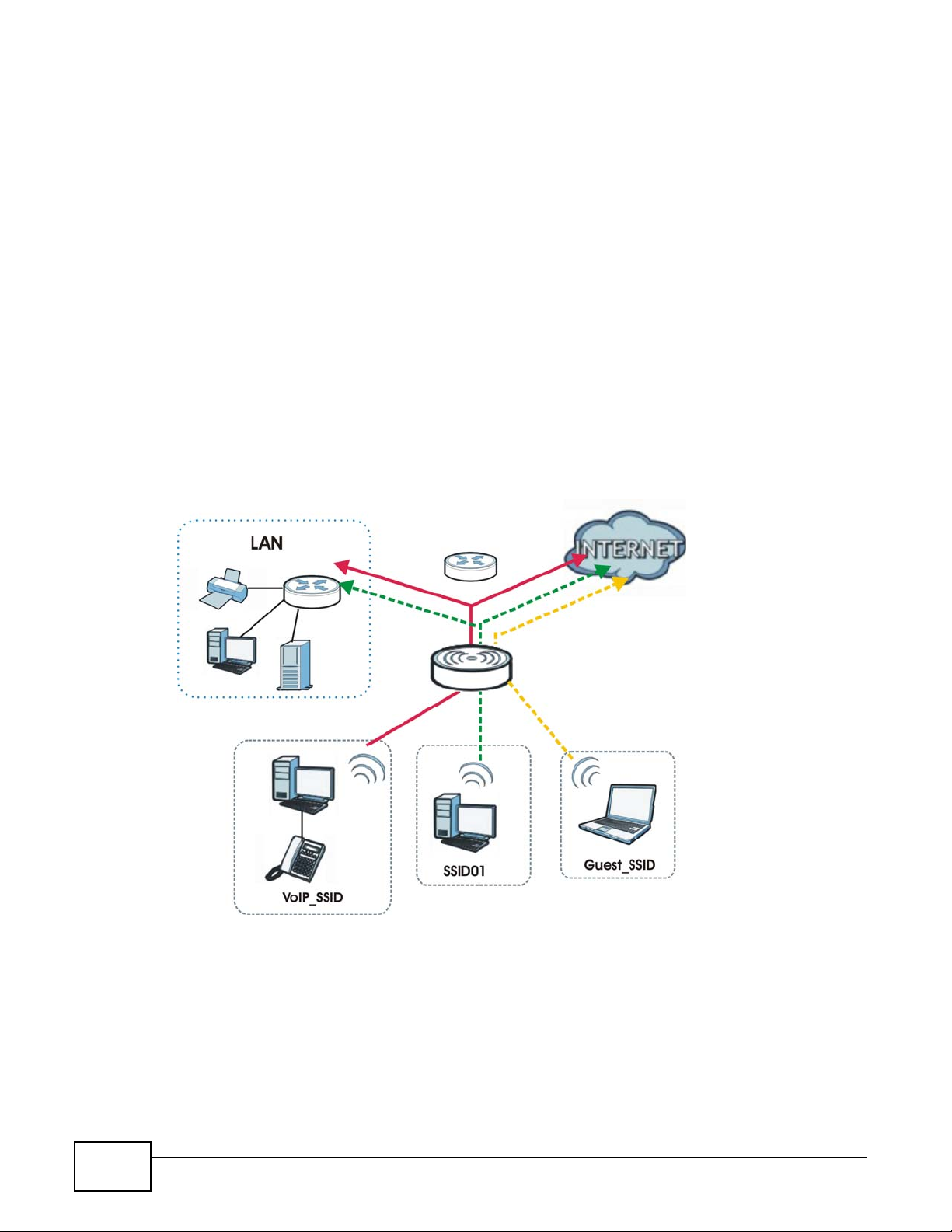
For example, you might want to set up a wireless network in your office where Internet telephony
(VoIP) users have priority. You also want a regular wireless network for standard users, as well as a
‘guest’ wireless network for visitors. In the following figure, VoIP_SSID users have QoS priority,
SSID01 is the wireless network for standard users, and Guest_SSID is the wireless network for
guest users. In this example, the guest user is forbidden access to the wired Land Area Network
(LAN) behind the AP and can access only the Internet.
Figure 1 Multiple BSSs
12
NWA1121-NI User’s Guide
Page 13
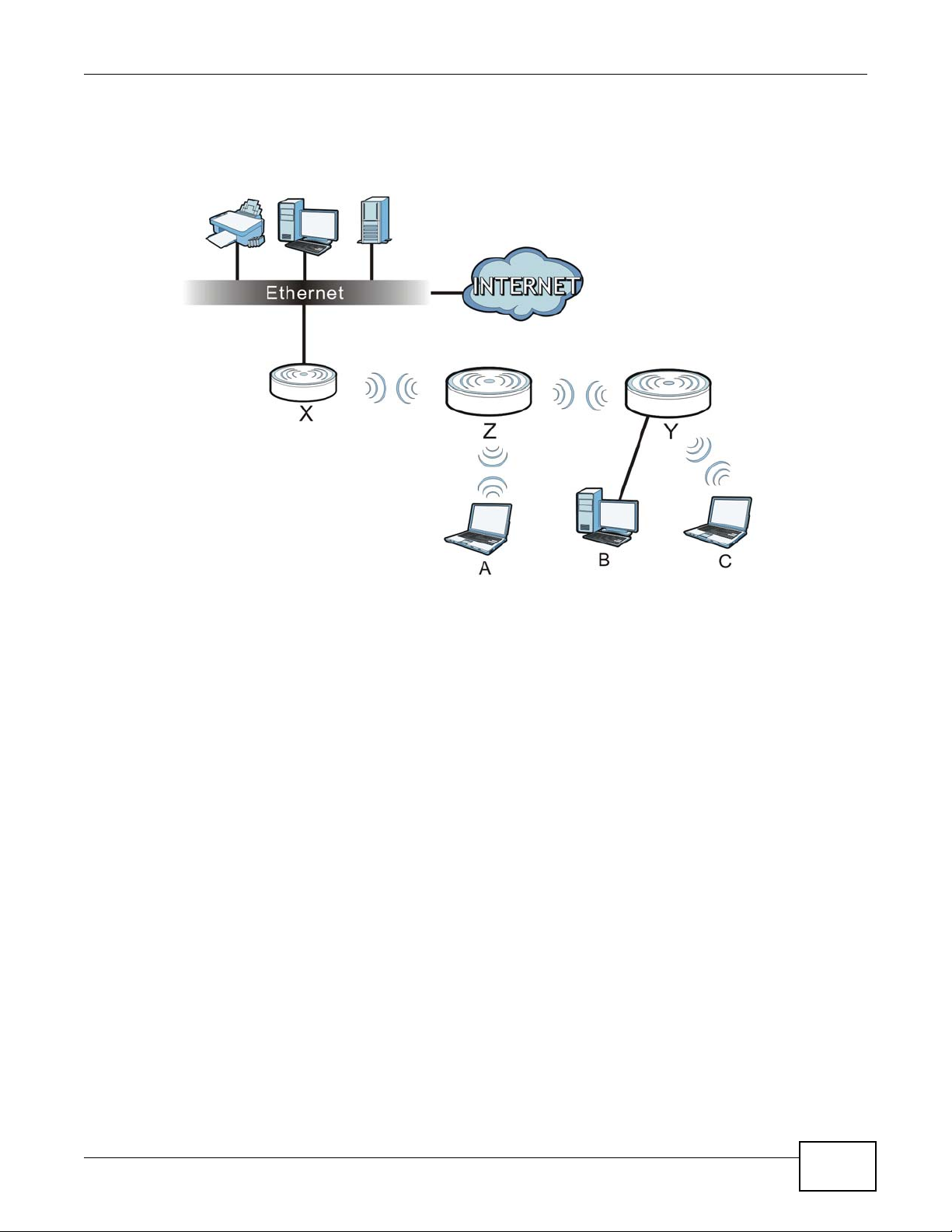
1.2.2 Wireless Client
The NWA1121-NI can be used as a wireless client to communicate with an existing network. In the
figure below, the printer can receive requests from the wired computer clients A and B via the
NWA1121-NI in Client mode (Z).
Figure 2 Wireless Client Application
Chapter 1 Introducing the NWA1121-NI
NWA1121-NI User’s Guide
13
Page 14
Chapter 1 Introducing the NWA1121-NI
1.2.3 Root AP
In Root AP mode, the NWA1121-NI (Z) can act as the root AP in a wireless network and also allow
repeaters (X and Y) to extend the range of its wireless network at the same time. In the figure
below, both clients A, B and C can access the wired network through the root AP.
Figure 3 Root AP Application
On the NWA1121-NI in Root AP mode, you can have multiple SSIDs active for reqular wireless
connections and one SSID for the connection with a repeater (universal repeater SSID). Wireless
clients can use either SSID to associate with the NWA1121-NI in Root AP mode. A repeater must
use the universal repeater SSID to connect to the NWA1121-NI in Root AP mode.
When the NWA1121-NI is in Root AP mode, universal repeater security between the NWA1121-NI
and other repeater is independent of the security between the wireless clients and the AP or
repeater. If you do not enable universal repeater security, traffic between APs is not encrypted.
When universal repeater security is enabled, both APs and repeaters must use the same pre-shared
key. See Section 6.6 on page 74 for more details.
Unless specified, the term “security settings” refers to the traffic between the wireless clients and
the AP. At the time of writing, universal repeater security is compatible with the NWA1121-NI only.
1.2.4 Repeater
The NWA can act as a wireless network repeater to extend a root AP’s wireless network range, and
also establish wireless connections with wireless clients.
Using Repeater mode, your NWA1121-NI can extend the range of the WLAN. In the figure below,
the NWA1121-NI in Repeater mode (Z) has a wireless connection to the NWA1121-NI in Root AP
mode (X) which is connected to a wired network and also has a wireless connection to another
NWA1121-NI in Repeater mode (Y) at the same time. Z and Y act as repeaters that forward traffic
14
NWA1121-NI User’s Guide
Page 15
Chapter 1 Introducing the NWA1121-NI
between associated wireless clients and the wired LAN. Clients A, B and C access the AP and the
wired network behind the AP throught repeaters Z and Y.
Figure 4 Repeater Application
When the NWA1121-NI is in Repeater mode, universal repeater security between the NWA1121-NI
and other repeater is independent of the security between the wireless clients and the AP or
repeater. If you do not enable universal repeater security, traffic between APs is not encrypted.
When universal repeater security is enabled, both APs and repeaters must use the same pre-shared
key. See Section 6.6 on page 74 for more details.
Once the security settings of peer sides match one another, the connection between devices is
made.
At the time of writing, universal repeater security is compatible with the NWA1121-NI only.
1.3 Ways to Manage the NWA1121-NI
Use any of the following methods to manage the NWA1121-NI.
• Web Configurator. This is recommended for everyday management of the NWA1121-NI using a
(supported) web browser.
• FTP (File Transfer Protocol) for firmware upgrades and configuration backup and restore.
• SNMP (Simple Network Management Protocol). The device can be monitored by an SNMP
manager.
NWA1121-NI User’s Guide
15
Page 16
Chapter 1 Introducing the NWA1121-NI
1.4 Configuring Your NWA1121-NI’s Security Features
Your NWA1121-NI comes with a variety of security features. This section summarizes these
features and provides links to sections in the User’s Guide to configure security settings on your
NWA1121-NI. Follow the suggestions below to improve security on your NWA1121-NI and network.
1.4.1 Control Access to Your Device
Ensure only people with permission can access your NWA1121-NI.
• Control physical access by locating devices in secure areas, such as locked rooms. Most
NWA1121-NIs have a reset button. If an unauthorized person has access to the reset button,
they can then reset the device’s password to its default password, log in and reconfigure its
settings.
• Change any default passwords on the NWA1121-NI, such as the password used for accessing the
NWA1121-NI’s web configurator (if it has a web configurator). Use a password with a
combination of letters and numbers and change your password regularly. Write down the
password and put it in a safe place.
•See Section 11.5 on page 121 for instructions on changing your password.
• Configure remote management to control who can manage your NWA1121-NI. See Chapter 9 on
page 101 for more information. If you enable remote management, ensure you have enabled
remote management only on the IP addresses, services or interfaces you intended and that other
remote management settings are disabled.
1.4.2 Wireless Security
Wireless devices are especially vulnerable to attack. Take the following measures to improve
wireless security.
• Enable wireless security on your NWA1121-NI. Choose the most secure encryption method that
all devices on your network support. See Section 6.6 on page 74 for directions on configuring
encryption. If you have a RADIUS server, enable IEEE 802.1x or WPA(2) user identification on
your network so users must log in. This method is more common in business environments.
• Hide your wireless network name (SSID). The SSID can be regularly broadcast and unauthorized
users may use this information to access your network. See Section 6.5 on page 72 for directions
on using the web configurator to hide the SSID.
• Enable the MAC filter to allow only trusted users to access your wireless network or deny
unwanted users access based on their MAC address. See Section 6.8 on page 89 for directions on
configuring the MAC filter.
1.5 Good Habits for Managing the NWA1121-NI
Do the following things regularly to make the NWA1121-NI more secure and to manage it more
effectively.
• Change the password. Use a password that’s not easy to guess and that consists of different
types of characters, such as numbers and letters.
• Write down the password and put it in a safe place.
16
NWA1121-NI User’s Guide
Page 17
• Back up the configuration (and make sure you know how to restore it). Restoring an earlier
working configuration may be useful if the device becomes unstable or even crashes. If you
forget your password, you will have to reset the NWA1121-NI to its factory default settings. If
you backed up an earlier configuration file, you would not have to totally re-configure the
NWA1121-NI. You could simply restore your last configuration.
1.6 Hardware Connections
See your Quick Start Guide for information on making hardware connections.
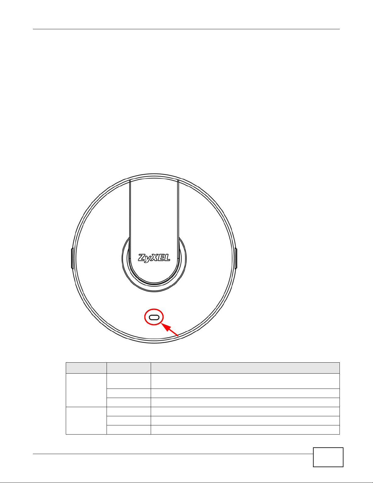
1.7 LED
Figure 5 LED
Chapter 1 Introducing the NWA1121-NI
Table 1 LED
COLORSTATUSDESCRIPTION
AmberOnThere is system error and the NWA1121-NI cannot boot up, or the
GreenOnThe WLAN is active.
NWA1121-NI User’s Guide
NWA1121-NI doesn’t have an Ethernet connection with the LAN.
FlashingThe NWA1121-NI is starting up.
OffThe NWA1121-NI is receiving power and ready for use.
BlinkingThe WLAN is active, and transmitting or receiving data.
OffThe WLAN is not active.
17
Page 18
Chapter 1 Introducing the NWA1121-NI
18
NWA1121-NI User’s Guide
Page 19
CHAPTER 2
Introducing the Web Configurator
This chapter describes how to access the NWA1121-NI’s web configurator and provides an overview
of its screens.
2.1 Accessing the Web Configurator
1Make sure your hardware is properly connected and prepare your computer or computer network to
connect to the NWA1121-NI (refer to the Quick Start Guide).
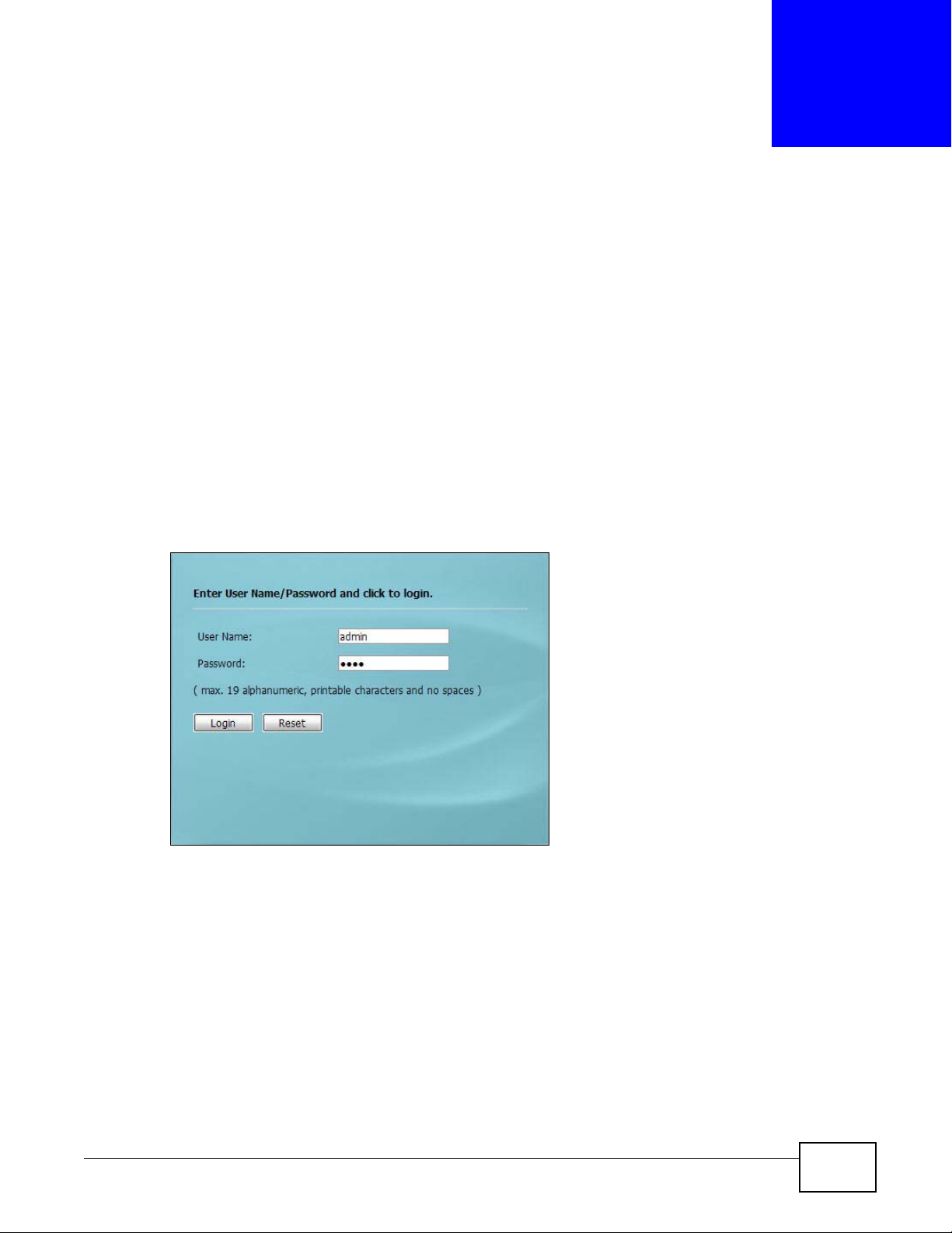
2Launch your web browser.
3Type "192.168.1.2" as the URL (default). The login screen appears.
Figure 6 The Login Screen
4Type “admin” as the (default) username and “1234” as the (default) password. Click Login.
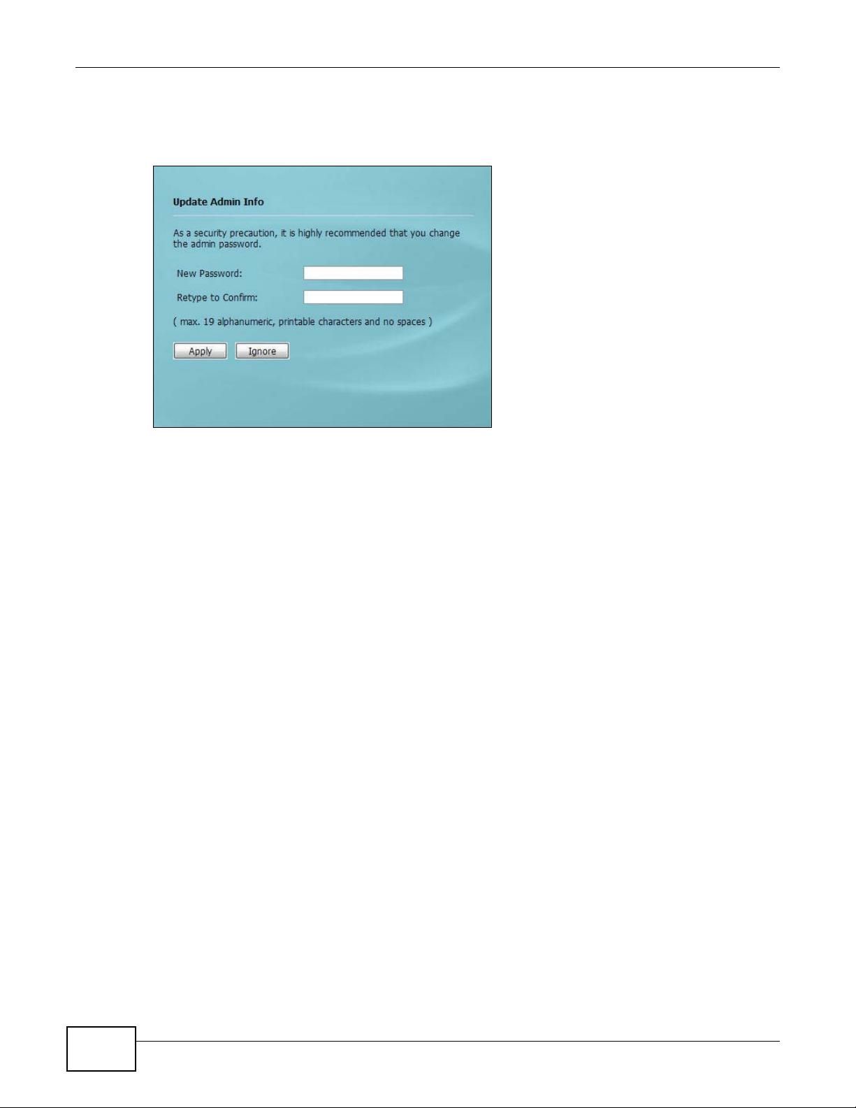
5You should see a screen asking you to change your password (highly recommended) as shown
next. Type a new password (and retype it to confirm) then click Apply. Alternatively, click Ignore.
NWA1121-NI User’s Guide19
Page 20
Chapter 2 Introducing the Web Configurator
Note: If you do not change the password, the following screen appears every time you
login.
Figure 7 Change Password Screen
You should now see the Dashboard screen. See Chapter 2 on page 19 for details about the
Dashboard screen.
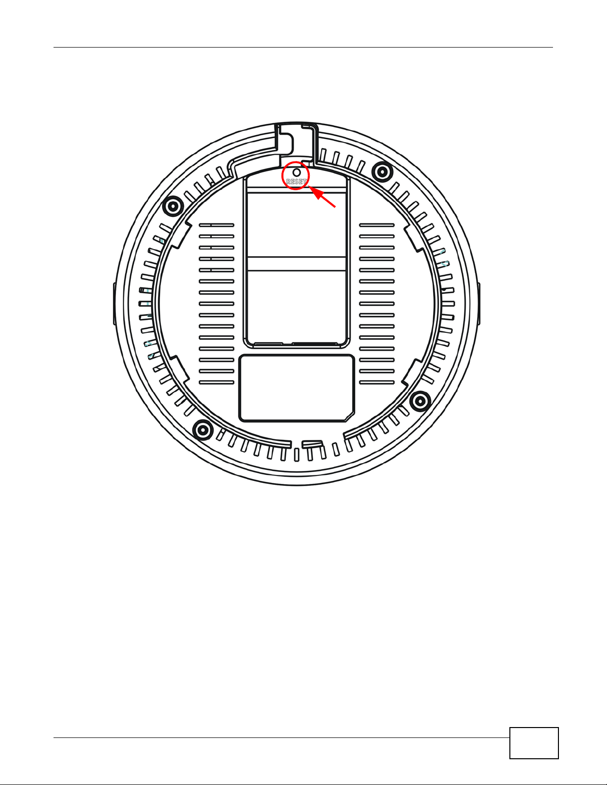
2.2 Resetting the NWA1121-NI
If you forget your password or cannot access the web configurator, you will need to use the RESET
button at the rear panel of the NWA1121-NI. This replaces the current configuration file with the
20
NWA1121-NI User’s Guide
Page 21
Chapter 2 Introducing the Web Configurator
factory-default configuration file. This means that you will lose all the settings you previously
configured. The password will be reset to “1234”.
Figure 8 The RESET Button
2.2.1 Methods of Restoring Factory-Defaults
You can erase the current configuration and restore factory defaults in two ways:
Use the RESET button to upload the default configuration file. Hold this button in for about 3
seconds (the light will begin to blink). Use this method for cases when the password or IP address
of the NWA1121-NI is not known.
Use the web configurator to restore defaults (refer to Section 11.8 on page 124).
NWA1121-NI User’s Guide
21
Page 22
Chapter 2 Introducing the Web Configurator
A
B
C
2.3 Navigating the Web Configurator
The following summarizes how to navigate the web configurator from the Dashboard screen.
Figure 9 Status Screen of the Web Configurator
As illustrated above, the Web Configurator screen is divided into these parts:
• A - title bar
• B - navigation panel
• C - main window
2.3.1 Title Bar
Click Logout at any time to exit the Web Configurator.
Click ZAbout to open the about window, which provides information of the boot module and driver
versions.
22
NWA1121-NI User’s Guide
Page 23
2.3.2 Navigation Panel
Use the menu items on the navigation panel to open screens to configure NWA1121-NI features.
The following tables describe each menu item.
Table 2 Navigation Panel Summary
LINKTABFUNCTION
DashboardThis screen shows the NWA1121-NI’s general device and network
Monitor
LogsView LogUse this screen to view the logs for the categories that you selected.
StatisticsUse this screen to view port status, packet specific statistics, the
Association ListUse this screen to view the wireless stations that are currently
Channel UsageUse this screen to know whether a channel is used by another
Configuration
Network
Wireless LANWireless
Settings
SSIDUse this screen to configure up to eight SSID profiles for your
SecurityUse this screen to configure wireless security profiles on the
RADIUSUse this screen to configure up to four RADIUS profiles.
MAC FilterUse this screen to configure MAC filtering profiles.
LANUse this screen to configure the NWA1121-NI’s LAN IP address.
VLANUse this screen to configure the NWA1121-NI’s VLAN settings.
SystemWWWUse this screen to configure through which interface(s) and from
CertificatesUse this screen to import or remove a certificate from the NWA1121-
TelentUse this screen to configure through which interface(s) and from
SNMPUse this screen to configure the NWA1121-NI for SNMP management.
FTPUse this screen to configure through which interface(s) and from
Log SettingsUse this screen to change your log settings.
Maintenance
GeneralUse this screen to configure your device’s name.
PasswordUse this screen to configure your device’s password.
TimeUse this screen to change your NWA1121-NI’s time and date.
Firmware UpgradeUse this screen to upload firmware to your device.
Chapter 2 Introducing the Web Configurator
status information. Use this screen to access the statistics and client
list.
"system up time" and so on.
associated to the NWA1121-NI.
wireless network or not.
Use this screen to configure the wireless LAN settings and NWA1121NI’s operation mode.
NWA1121-NI.
NWA1121-NI.
which IP address(es) users can use HTTP to manage the NWA1121NI.
NI.
which IP address(es) users can use Telnet to manage the NWA1121NI.
which IP address(es) users can use FTP to access the NWA1121-NI.
NWA1121-NI User’s Guide
23
Page 24
Chapter 2 Introducing the Web Configurator
Table 2 Navigation Panel Summary
LINKTABFUNCTION
Configuration FileUse this screen to backup and restore your device’s configuration
RestartUse this screen to reboot the NWA1121-NI without turning the power
2.3.3 Main Window
The main window displays information and configuration fields. It is discussed in the rest of this
document.
(settings) or reset the factory default settings.
off.
24
NWA1121-NI User’s Guide
Page 25
The Dashboard screens display when you log into the NWA1121-NI, or click Dashboard in the
navigation menu.
Use the Dashboard screen to look at the current status of the device, system resources, and
interfaces. The Dashboard screens also provide detailed information about system statistics,
associated wireless clients, and logs.
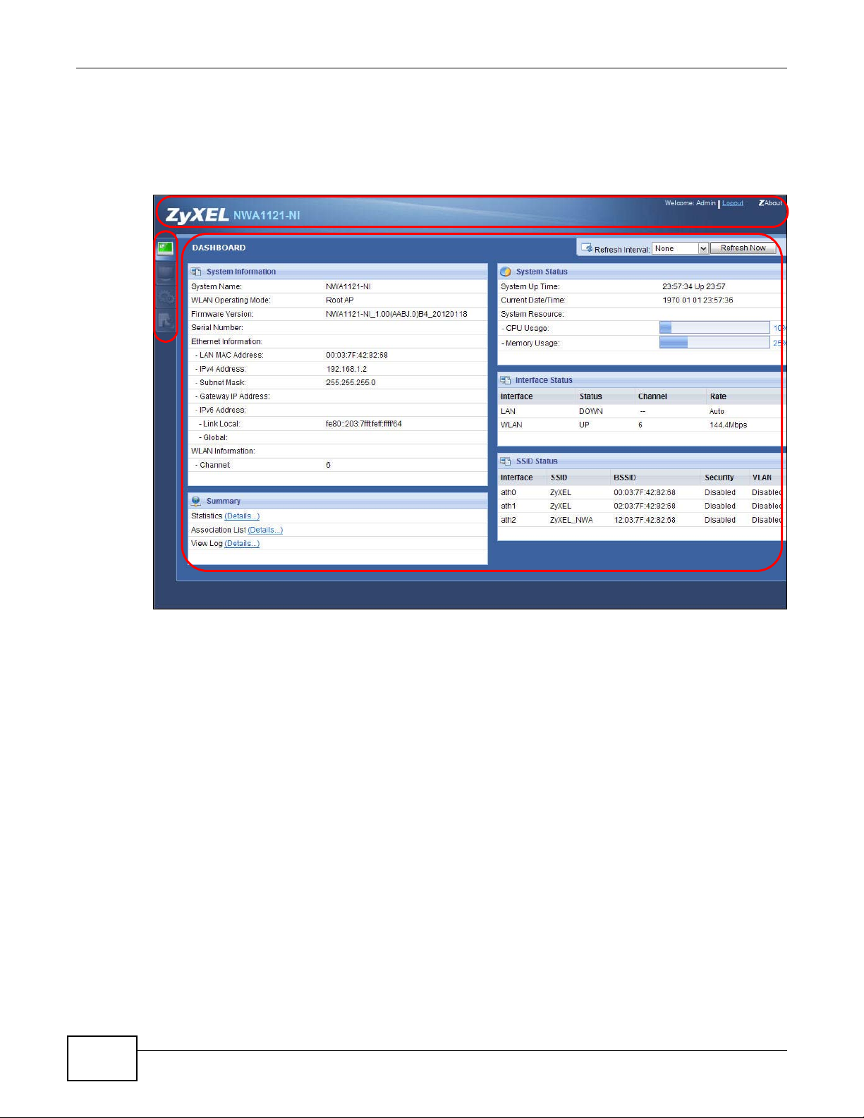
3.1 The Dashboard Screen
Use this screen to get a quick view of system, Ethernet, WLAN and other information regarding
your NWA1121-NI.
Click Dashboard. The following screen displays.
CHAPTER 3
Dashboard
Figure 10 The Dashboard Screen
NWA1121-NI User’s Guide25
Page 26
Chapter 3 Dashboard
The following table describes the labels in this screen.
Table 3 The Dashboard Screen
LABELDESCRIPTION
Refresh IntervalSelect how often you want the NWA1121-NI to update this screen.
Refresh NowClick this to update this screen immediately.
System Information
System NameThis field displays the NWA1121-NI system name. It is used for identification. You
WLAN Operating
Mode
Firmware VersionThis field displays the current version of the firmware inside the device. It also
Serial NumberThis field displays the serial number of the NWA1121-NI.
Ethernet Information
LAN MAC AddressThis displays the MAC (Media Access Control) address of the NWA1121-NI on the
IPv4 AddressThis field displays the current IPv4 address of the NWA1121-NI on the network.
Subnet MaskSubnet masks determine the maximum number of possible hosts on a network.
Gateway IP AddressThis is the IP address of the gateway. The gateway is a router or switch on the
IPv6 AddressThis field displays the current IPv6 address(es) of the NWA1121-NI on the
Link LocalThis is the IPv6 link-local address that the NWA1121-NI generates automatically.
GlobalThis is the NWA1121-NI’s IPv6 global address that you specify manually in the
WLAN Information
SSIDThis field displays the SSID (Service Set Identifier). This is available only when the
ChannelThe channel or frequency used by the NWA1121-NI to send and receive
StatusThis shows the current status of the wireless LAN. This is available only when the
Security ModeThis displays the security mode the NWA1121-NI is using. This is available only
Summary
StatisticsClick this link to view port status and packet specific statistics. See Section 5.4 on
Association ListClick this to see a list of wireless clients currently associated to each of the
View LogClick this to see a list of logs produced by the NWA1121-NI. See Section 5.3 on
System Status
System Up TimeThis field displays the elapsed time since the NWA1121-NI was turned on.
can change this in the Maintenance > General screen’s System Name field.
This field displays the current operating mode of the wireless module (Root AP,
Repeater, Client, or MBSSID). You can change the operating mode in the
Configuration > Wireless LAN > Wireless Settings screen.
shows the date the firmware version was created. You can change the firmware
version by uploading new firmware in Maintenance > Firmware Upgrade.
LAN. Every network device has a unique MAC address which identifies it across the
network.
You can also use subnet masks to divide one network into multiple sub-networks.
same network segment as the device's LAN port. The gateway helps forward
packets to their destinations.
network.
Configuration > LAN screen.
WLAN operation mode is Client.
information.
WLAN operation mode is Client.
when the WLAN operation mode is Client.
page 50.
NWA1121-NI’s wireless modules. See Section 5.5 on page 51.
page 49.
26
NWA1121-NI User’s Guide
Page 27
Chapter 3 Dashboard
Table 3 The Dashboard Screen (continued)
LABELDESCRIPTION
Current Date/TimeThis field displays the date and time configured on the NWA1121-NI. You can
change this in the Maintenance > Time screen.
System Resource
CPU UsageThis field displays what percentage of the NWA1121-NI’s processing ability is
currently being used. The higher the CPU usage, the more likely the NWA1121-NI
is to slow down.
Memory UsageThis field displays what percentage of the NWA1121-NI’s volatile memory is
currently in use. The higher the memory usage, the more likely the NWA1121-NI is
to slow down. Some memory is required just to start the NWA1121-NI and to run
the web configurator.
Interface Status
InterfaceThis column displays each interface of the NWA1121-NI.
StatusThis field indicates whether or not the NWA1121-NI is using the interface.
For each interface, this field displays Up when the NWA1121-NI is using the
interface and Down when the NWA1121-NI is not using the interface.
ChannelThis shows the channel number which the NWA1121-NI is currently using over the
RateFor the LAN port this displays the port speed and duplex setting.
SSID StatusThis section is not available when the WLAN operation mode is Client.
InterfaceThis column displays each of the NWA1121-NI’s wireless interfaces.
SSIDThis field displays the SSID(s) currently used by each wireless module.
BSSIDThis field displays the MAC address of the wireless module.
SecurityThis field displays the type of wireless security used by each SSID.
VLANThis field displays the VLAN ID of each SSID in use, or Disabled if the SSID does
wireless LAN.
For the WLAN interface, it displays the downstream and upstream transmission
rate or N/A if the interface is not in use.
not use VLAN.
NWA1121-NI User’s Guide
27
Page 28
Chapter 3 Dashboard
28
NWA1121-NI User’s Guide
Page 29
CHAPTER 4
This chapter first provides an overview of how to configure the wireless LAN on your NWA1121-NI,
and then gives step-by-step guidelines showing how to configure your NWA1121-NI for some
example scenarios.
4.1 How to Configure the Wireless LAN
This section illustrates how to choose which wireless operating mode to use on the NWA1121-NI
and how to set up the wireless LAN in each wireless mode. See Section 4.1.2 on page 29 for links to
more information on each step.
4.1.1 Choosing the Wireless Mode
Tutorial
•Use MBSSID (Multiple Basic Service Set Identifier) operating mode if you want to use the
NWA1121-NI as an access point with some groups of users having different security or QoS
settings from other groups of users. See Section 1.2.1 on page 11 for details.
•Use Client operating mode if you want to use the NWA1121-NI to access a wireless network. See
Section 1.2.2 on page 13 for details.
•Use Root AP operating mode if you want to allow wireless clients to access your wired network
through the NWA1121-NI and also have repeaters communicate with the NWA1121-NI to expand
wireleass coverage. See Section 1.2.3 on page 14 for details.
•Use Repeater operating mode if you want to use the NWA1121-NI to communicate with the root
AP or other repeaters. See Section 1.2.4 on page 14 for details.
4.1.2 Further Reading
Use these links to find more information on the steps:
• Choosing 802.11 Mode: see Section 6.4 on page 60.
• Choosing a wireless Channel ID: see Section 6.4 on page 60.
• Choosing a Security mode: see Section 6.6 on page 74.
• Configuring an external RADIUS server: see Section 6.7 on page 87.
•Configuring MAC Filtering: see Section 6.8 on page 89.
4.2 How to Configure Multiple Wireless Networks
In this example, you have been using your NWA1121-NI as an access point for your office network.
Now your network is expanding and you want to make use of the MBSSID feature (see Section
NWA1121-NI User’s Guide29
Page 30
Chapter 4 Tutorial
Z
A
B
6.4.4 on page 69) to provide multiple wireless networks. Each wireless network will cater to a
different type of user.
You want to make three wireless networks: one standard office wireless network with all the same
settings you already have, another wireless network with high priority QoS settings for Voice over
IP (VoIP) users, and a guest network that allows visitors to access only the Internet and the
network printer.
To do this, you will take the following steps:
1Edit the SSID profiles.
2Change the operating mode from Root AP to MBSSID and reactivate the standard network.
3Configure different security modes for the networks.
4Configure a wireless network for standard office use.
5Configure a wireless network for VoIP users.
6Configure a wireless network for guests to your office.
The following figure shows the multiple networks you want to set up. Your NWA1121-NI is marked
Z, the main network router is marked A, and your network printer is marked B.
30
The standard network (SSID01) has access to all resources. The VoIP network (VoIP_SSID) has
access to all resources and a high QoS priority. The guest network (Guest_SSID) has access to the
Internet and the network printer only, and a low QoS priority.
NWA1121-NI User’s Guide
Page 31
To configure these settings, you need to know the Media Access Control (MAC) addresses of the
devices you want to allow users of the guest network to access. The following table shows the
addresses used in this example.
Table 4 Tutorial: Example Information
Network router (A) MAC address00:AA:00:AA:00:AA
Network printer (B) MAC addressAA:00:AA:00:AA:00
4.2.1 Configure the SSID Profiles
1Log in to the NWA1121-NI (see Section 2.1 on page 19). Click Wireless LAN > SSID. The SSID
screen appears.
2Click the Edit icon next to the Profile1.
Chapter 4 Tutorial
3Rename the Profile Name and SSID as SSID01. Click Apply.
4Repeat Step 2 and 3 to change Profile2 and Profile3 to VoIP_SSID and Guest_SSID.
NWA1121-NI User’s Guide
31
Page 32
Chapter 4 Tutorial
4.2.1.1 MBSSID
1Go to Wireless LAN > Wireless Settings. Select MBSSID from the Operation Mode drop-down
list box.
2SSID01 is the standard network, so select SSID01 as the first profile. It is always active.
3Select VoIP_SSID as the second profile, and Guest_SSID as the third profile. Select the
corresponding Active check-boxes.
4Click Apply to save your settings. Now the three SSIDs are activated.
32
NWA1121-NI User’s Guide
Page 33
4.2.2 Configure the Standard Network
1Click Wireless LAN > SSID. Click the Edit icon next to SSID01.
2Select SecProfile1 as SSID01’s security profile. Select the Hidden SSID checkbox as you want
only authorized company employees to use this network, so there is no need to broadcast the SSID
to wireless clients scanning the area.
Chapter 4 Tutorial
Also, the clients on SSID01 might need to access other clients on the same wireless network. Do
not select the Intra-BSS Traffic blocking check-box.
Click Apply.
NWA1121-NI User’s Guide
33
Page 34
Chapter 4 Tutorial
3Next, click Wireless LAN > Security. Click the Edit icon next to SecProfile1.
4Since SSID01 is the standard network that has access to all resources, assign a more secure
security mode. Select WPA2-PSK-MIX as the Security Mode, and enter the Pre-Shared Key. In
this example, use ThisisSSID01PreSharedKey. Click Apply.
5You have finished configuring the standard network, SSID01.
4.2.3 Configure the VoIP Network
1Go to Wireless LAN > SSID. Click the Edit icon next to VoIP_SSID.
2Select SecProfile2 as the Security Profile for the VoIP network. Select the Hidden SSID check-
box.
34
NWA1121-NI User’s Guide
Page 35
Chapter 4 Tutorial
3Select WMM_VOICE in the QoS field to give VoIP the highest priority in the wireless network. Click
Apply.
4Next, click Wireless LAN > Security. Click the Edit icon next to SecProfile2.
NWA1121-NI User’s Guide
35
Page 36
Chapter 4 Tutorial
5Select WPA2-PSK as the Security Mode, and enter the Pre-Shared Key. In this example, use
ThisisVoIPPreSharedKey. Click Apply.
6Your VoIP wireless network is now ready to use. Any traffic using the VoIP_SSID profile will be
given the highest priority across the wireless network.
4.2.4 Configure the Guest Network
When you are setting up the wireless network for guests to your office, your primary concern is to
keep your network secure while allowing access to certain resources (such as a network printer, or
the Internet). For this reason, the pre-configured Guest_SSID profile has intra-BSS traffic blocking
enabled by default. “Intra-BSS traffic blocking” means that the client cannot access other clients on
the same wireless network.
1Click Wireless LAN > SSID. Click the Edit icon next to Guest_SSID.
2Select SecProfile3 in the Security field. Do not select the Hidden SSID check-box so the guests
can easily find the wireless network.
3Select WMM_BESTEFFORT in the QoS field to give the guest a lower QoS priority.
36
NWA1121-NI User’s Guide
Page 37
4Select the check-box of Intra-BSS Traffic blocking Enabled. Click Apply.
Chapter 4 Tutorial
5Next, click Wireless LAN > Security. Click the Edit icon next to SecProfile3.
6Select WPA-PSK in the Security Mode field. WPA-PSK provides strong security that is supported
by most wireless clients. Even though your Guest_SSID clients do not have access to sensitive
information on the network, you should not leave the network without security. An attacker could
still cause damage to the network or intercept unsecured communications or use your Internet
access for illegal activities.
NWA1121-NI User’s Guide
37
Page 38
Chapter 4 Tutorial
7Enter the PSK you want to use in your network in the Pre Shared Key field. In this example, the
PSK is ThisismyGuestWPApre-sharedkey. Click Apply.
8Your guest wireless network is now ready to use.
4.2.5 Testing the Wireless Networks
To make sure that the three networks are correctly configured, do the following.
• On a computer with a wireless client, scan for access points. You should see the Guest_SSID
network, but not the SSID01 and VoIP_SSID networks. If you can see the SSID01 and
VoIP_SSID networks, go to its SSID Edit screen and make sure to select the Hidden SSID
check-box and click Apply.
• Try to access each network using the correct security settings, and then using incorrect security
settings, such as the WPA-PSK for another active network. If the behavior is different from
expected (for example, if you can access the SSID01 or VoIP_SSID wireless network using the
security settings for the Guest_SSID wireless network) check that the SSID profile is set to use
the correct security profile, and that the settings of the security profile are correct.
4.3 NWA1121-NI Setup in AP and Wireless Client Modes
This example shows you how to restrict wireless access to your NWA1121-NI.
4.3.1 Scenario
In the figure below, there are two NWA1121-NIs (A and B) in the network. A is in MBSSID or root
AP mode while station B is in wireless client mode. Station B is connected to a File Transfer Protocol
(FTP) server. You want only specified wireless clients to be able to access station B. You also want
38
NWA1121-NI User’s Guide
Page 39
Chapter 4 Tutorial
to allow wireless traffic between B and wireless clients connected to A (W, Y and Z). Other wireless
devices (X) must not be able to connect to the FTP server.
Figure 11 FTP Server Connected to a Wireless Client
4.3.2 Configuring the NWA1121-NI in MBSSID or Root AP Mode
Before setting up the NWA1121-NI as a wireless client (B), you need to make sure there is an
access point to connect to. Use the Ethernet port on NWA1121-NI (A) to configure it via a wired
connection.
NWA1121-NI User’s Guide
39
Page 40
Chapter 4 Tutorial
Log into the Web Configurator on NWA1121-NI (A) and go to the Wireless LAN > Wireless
Settings screen.
1Set the Operation Mode to Root AP.
2Select the Wireless Mode. In this example, select 802.11b/g/n.
3Select Profile1 as the SSID Profile.
4Choose the Channel you want NWA1121-NI (A) to use.
5Click Apply.
40
NWA1121-NI User’s Guide
Page 41
Chapter 4 Tutorial
6Go to Wireless LAN > SSID. Click the Edit icon next to Profile1.
7Change the SSID to AP-A.
8Select SecProfile1 in the Security field.
9Select the check-box for Intra-BSS Traffic blocking Enabled so the client cannot access other
clients on the same wireless network.
10 Click Apply.
NWA1121-NI User’s Guide
41
Page 42
Chapter 4 Tutorial
11 Go to Wireless LAN > Security. Click the Edit icon next to SecProfile1.
12 Configure WPA-PSK as the Security Mode and enter ThisisMyPreSharedKey in the Pre-
Shared Key field.
13 Click Apply to finish configuration for NWA1121-NI (A).
4.3.3 Configuring the NWA1121-NI in Wireless Client Mode
The NWA1121-NI (B) should have a wired connection before it can be set to wireless client
operating mode. Connect your NWA1121-NI to the FTP server. Login to NWA1121-NI (B)’s Web
Configurator and go to the Wireless LAN > Wireless Settings screen. Follow these steps to
configure station B.
42
NWA1121-NI User’s Guide
Page 43
1Select Client as Operation Mode. Click Apply.
Chapter 4 Tutorial
2Click on the Site Survey button. A window should pop up which contains a list of all available
wireless devices within your NWA1121-NI’s range.
3Find and select NWA1121-NI (A)’s SSID: AP-A.
NWA1121-NI User’s Guide
43
Page 44
Chapter 4 Tutorial
4Go to Wireless LAN > Security to configure the NWA1121-NI to use the same security mode and
Pre-Shared Key as NWA1121-NI (A): WPA-PSK/ThisisMyPreSharedKey. Click Apply.
Figure 12
4.3.4 MAC Filter Setup
One way to ensure that only specified wireless clients can access the FTP server is by enabling MAC
filtering on NWA1121-NI (B) (See Section 6.8 on page 89 for more information on MAC Filter).
1Go to Wireless LAN > MAC Filter. Click the Edit icon next to MacProfile1.
2Select Allow in the Access Control Mode field. Enter the MAC addresses of the wireless clients
(W, Y and Z) you want to associate with the NWA1121-NI. Click Apply.
Now, only the authorized wireless clients (W, Y and Z) can access the FTP server.
44
NWA1121-NI User’s Guide
Page 45
4.3.5 Testing the Connection and Troubleshooting
This section discusses how you can check if you have correctly configured your network setup as
described in this tutorial.
• Try accessing the FTP server from wireless clients W, Y or Z. Test if you can send or retrieve a
file. If you cannot establish a connection with the FTP server, do the following steps.
1Make sure W, Y and Z use the same wireless security settings as A and can access A.
2Make sure B uses the same wireless and wireless security settings as A and can access A.
3Make sure intra-BSS traffic is enabled on A.
• Try accessing the FTP server from X. If you are able to access the FTP server, do the following.
1Make sure MAC filtering is enabled.
2Make sure X’s MAC address is not entered in the list of allowed devices.
Chapter 4 Tutorial
NWA1121-NI User’s Guide
45
Page 46
Chapter 4 Tutorial
46
NWA1121-NI User’s Guide
Page 47
PART II
Technical Reference
The appendices provide general information. Some details may not apply to your NWA1121-NI.
47
Page 48
48
Page 49
5.1 Overview
This chapter discusses read-only information related to the device state of the NWA1121-NI.
Note: To access the Monitor screens, you can also click the links in the Summary table of
the Dashboard screen to view the wireless packets sent/received as well as the
status of clients connected to the NWA1121-NI.
5.2 What You Can Do
•Use the Logs screen to see the logs for the categories that you selected in the Configuration >
Log Settings screen (see Section 5.3 on page 49). You can view logs in this page. Once the log
entries are all used, the log will wrap around and the old logs will be deleted.
•use the Statistics screen to view 802.11 mode, channel number, wireless packet specific
statistics and so on (see Section 5.4 on page 50).
•Use the Association List screen to view the wireless devices that are currently associated to the
NWA1121-NI (see Section 5.5 on page 51).
•Use the Channel Usage screen to view whether a channel is used by another wireless network
or not. If a channel is being used, you should select a channel removed from it by five channels
to completely avoid overlap (see Section 5.6 on page 52).
CHAPTER 5
Monitor
5.3 View Logs
Use the Logs screen to see the logged messages for the NWA1121-NI.
Log entries in red indicate system error logs. The log wraps around and deletes the old entries after
it fills.
NWA1121-NI User’s Guide49
Page 50
Chapter 5 Monitor
Click Monitor > Logs.
Figure 13 Logs
The following table describes the labels in this screen.
Table 5 Logs
LABELDESCRIPTION
Display Select a category of logs to view. Select All Log to view logs from all of the log
E-Mail Log NowClick E-Mail Log Now to send the log screen to the e-mail address specified in the Log
RefreshClick Refresh to renew the log screen.
Clear LogClick Clear Log to delete all the logs.
#This field is a sequential value and is not associated with a specific entry.
Time This field displays the time the log was recorded.
MessageThis field states the reason for the log.
SourceThis field lists the source IP address and the port number of the incoming packet.
5.4 Statistics
Use this screen to view read-only information, including 802.11 Mode, Channel ID, Retry Count and
FCS Error Count. Also provided is the "poll interval". The Poll Interval field is configurable and is
used for refreshing the screen.
categories that you selected in the Configuration > Log Settings screen.
Settings page (make sure that you have first filled in the E-mail Log Settings fields in
Configuration > Log Settings).
50
NWA1121-NI User’s Guide
Page 51
Chapter 5 Monitor
Click Monitor > Statistics. The following screen pops up.
Figure 14 Statistics
The following table describes the labels in this screen.
Table 6 Statistics
LABELDESCRIPTION
DescriptionThis is the wireless interface on the NWA1121-NI.
802.11 ModeThis field shows which 802.11 mode the NWA1121-NI is using.
Channel IDThis shows the channel number which the NWA1121-NI is currently using over the
RX PktsThis is the number of received packets on this port.
TX PktsThis is the number of transmitted packets on this port.
Retry CountThis is the total number of retries for transmitted packets (TX).
FCS Error CountThis is the total number of checksum error of received packets (RX).
Poll IntervalEnter the time interval for refreshing statistics.
Set IntervalClick this button to apply the new poll interval you entered above.
StopClick this button to stop refreshing statistics.
wireless LAN.
5.5 Association List
View the wireless devices that are currently associated with the NWA1121-NI in the Association
List screen. Association means that a wireless client (for example, your network or computer with
a wireless network card) has connected successfully to the AP (or wireless router) using the same
SSID, channel and security settings.
NWA1121-NI User’s Guide
51
Page 52
Chapter 5 Monitor
Click Monitor > Association List to display the screen as shown next.
Figure 15 Association List
The following table describes the labels in this screen.
Table 7 Association List
LABELDESCRIPTION
#This is the index number of an associated wireless device.
MAC AddressThis field displays the MAC address of an associated wireless device.
SSIDThis field displays the SSID to which the wireless device is associated.
Association TimeThis field displays the time a wireless device first associated with the NWA1121-NI’s
Signal StrengthThis field displays the RSSI (Received Signal Strength Indicator) of the wireless
RefreshClick Refresh to reload the list.
wireless network.
connection.
5.6 Channel Usage
Use this screen to know whether a channel is used by another wireless network or not. If a channel
is being used, you should select a channel removed from it by five channels to completely avoid
overlap.
Click Monitor > Channel Usage to display the screen shown next.
52
NWA1121-NI User’s Guide
Page 53
Wait a moment while the NWA1121-NI compiles the information.
Figure 16 Channel Usage
Chapter 5 Monitor
The following table describes the labels in this screen.
Table 8 Channel Usage
LABELDESCRIPTION
SSIDThis is the Service Set IDentification (SSID) name of the AP in an Infrastructure
wireless network or wireless station in an Ad-Hoc wireless network. For our purposes,
we define an Infrastructure network as a wireless network that uses an AP and an AdHoc network (also known as Independent Basic Service Set (IBSS)) as one that
doesn’t. See the chapter on wireless configuration for more information on basic
service sets (BSS) and extended service sets (ESS).
ChannelThis is the index number of the channel currently used by the associated AP in an
Infrastructure wireless network or wireless station in an Ad-Hoc wireless network.
MAC AddressThis field displays the MAC address of the AP in an Infrastructure wireless network. It
is randomly generated (so ignore it) in an Ad-Hoc wireless network.
Wireless ModeThis is the IEEE 802.1x standard used by the wireless network.
Signal StrengthThis field displays the strength of the AP’s signal. If you must choose a channel that is
SecurityThis is the wireless security method used by the wireless network to protect wireless
RefreshClick Refresh to reload the screen.
currently in use, choose one with low signal strength for minimum interference.
communication between wireless stations, access points and the wired network.
NWA1121-NI User’s Guide
53
Page 54
Chapter 5 Monitor
54
NWA1121-NI User’s Guide
Page 55
6.1 Overview
This chapter discusses the steps to configure the Wireless Settings screen on the NWA1121-NI. It
also introduces the wireless LAN (WLAN) and some basic scenarios.
Figure 17 Wireless Mode
CHAPTER 6
Wireless LAN
In the figure above, the NWA1121-NI allows access to another bridge device (A) and a notebook
computer (B) upon verifying their settings and credentials. It denies access to other devices (C and
D) with configurations that do not match those specified in your NWA1121-NI.
6.2 What You Can Do in this Chapter
•Use the Wireless Settings screen to configure the NWA1121-NI’s operation mode (see Section
6.4 on page 60).
•Uee the SSID screen to configure up to eight SSID profiles for your NWA1121-NI (see Section
6.5 on page 72).
•Use the Security screen to choose the wireless security mode for your NWA1121-NI (see Section
6.6 on page 74).
•Use the RADIUS screen if you want to authenticate wireless users using a RADIUS Server and/or
accounting server (see Section 6.7 on page 87).
•Use the MAC Filter screen to specify which wireless station is allowed or denied access to the
NWA1121-NI (see Section 6.8 on page 89).
NWA1121-NI User’s Guide55
Page 56
Chapter 6 Wireless LAN
6.3 What You Need To Know
BSS
A Basic Service Set (BSS) exists when all communications between wireless clients or between a
wireless client and a wired network client go through one access point (AP). Intra-BSS traffic is
traffic between wireless clients in the BSS.
ESS
An Extended Service Set (ESS) consists of a series of overlapping BSSs, each containing an access
point, with each access point connected together by a wired network. This wired connection
between APs is called a Distribution System (DS).
Operating Mode
The NWA1121-NI can run in four operating modes as follows:
• Root AP. The NWA1121-NI is a wireless access point that allows wireless communication to
other devices in the network.
• Repeater. The NWA1121-NI acts as a wireless repeater and increase a root AP’s wireless
coverage area.
• Client. The NWA1121-NI acts as a wireless client to access a wireless network.
• MBSSID. The Multiple Basic Service Set Identifier (MBSSID) mode allows you to use one
access point to provide several BSSs simultaneously.
Refer to Chapter 1 on page 11 for illustrations of these wireless applications.
SSID
The SSID (Service Set IDentifier) is the name that identifies the Service Set with which a wireless
station is associated. Wireless stations associating to the access point (AP) must have the same
SSID. In other words, it is the name of the wireless network that clients use to connect to it.
Normally, the NWA1121-NI acts like a beacon and regularly broadcasts the SSID in the area. You
can hide the SSID instead, in which case the NWA1121-NI does not broadcast the SSID. In
addition, you should change the default SSID to something that is difficult to guess.
This type of security is fairly weak, however, because there are ways for unauthorized wireless
devices to get the SSID. In addition, unauthorized wireless devices can still see the information that
is sent in the wireless network.
Channel
A channel is the radio frequency(ies) used by wireless devices. Channels available depend on your
geographical area. You may have a choice of channels (for your region) so you should use a
different channel than an adjacent AP (access point) to reduce interference.
56
NWA1121-NI User’s Guide
Page 57
Chapter 6 Wireless LAN
Wireless Mode
The IEEE 802.1x standard was designed to extend the features of IEEE 802.11 to support extended
authentication as well as providing additional accounting and control features. Your NWA1121-NI
can support 802.11b/g, 802.11n and 802.11b/g/n.
MBSSID
Traditionally, you needed to use different APs to configure different Basic Service Sets (BSSs). As
well as the cost of buying extra APs, there was also the possibility of channel interference. The
NWA1121-NI’s MBSSID (Multiple Basic Service Set IDentifier) function allows you to use one access
point to provide several BSSs simultaneously. You can then assign varying levels of privilege to
different SSIDs.
Wireless stations can use different BSSIDs to associate with the same AP.
The following are some notes on multiple BSS.
• A maximum of four BSSs are allowed on one AP simultaneously.
• You must use different WEP keys for different BSSs. If two stations have different BSSIDs (they
are in different BSSs), but have the same WEP keys, they may hear each other’s communications
(but not communicate with each other).
• MBSSID should not replace but rather be used in conjunction with 802.1x security.
Wireless Security
Wireless security is vital to your network. It protects communications between wireless stations,
access points and the wired network.
Figure 18 Securing the Wireless Network
In the figure above, the NWA1121-NI checks the identity of devices before giving them access to
the network. In this scenario, Computer A is denied access to the network, while Computer B is
granted connectivity.
The NWA1121-NI secure communications via data encryption, wireless client authentication and
MAC address filtering. It can also hide its identity in the network.
NWA1121-NI User’s Guide
57
Page 58
Chapter 6 Wireless LAN
User Authentication
Authentication is the process of verifying whether a wireless device is allowed to use the wireless
network. You can make every user log in to the wireless network before they can use it. However,
every device in the wireless network has to support IEEE 802.1x to do this.
For wireless networks, you can store the user names and passwords for each user in a RADIUS
server. This is a server used in businesses more than in homes. If you do not have a RADIUS server,
you cannot set up user names and passwords for your users.
Unauthorized wireless devices can still see the information that is sent in the wireless network,
even if they cannot use the wireless network. Furthermore, there are ways for unauthorized
wireless users to get a valid user name and password. Then, they can use that user name and
password to use the wireless network.
The following table shows the relative effectiveness of wireless security methods:.
Table 9 Wireless Security Levels
SECURITY
LEVEL
Least
Secure
Most Secure
SECURITY TYPE
Unique SSID (Default)
Unique SSID with Hide SSID Enabled
MAC Address Filtering
WEP Encryption
IEEE802.1x EAP with RADIUS Server Authentication
Wi-Fi Protected Access (WPA)
WPA2
The available security modes in your NWA1121-NI are as follows:
• None. No data encryption.
• WEP. Wired Equivalent Privacy (WEP) encryption scrambles the data transmitted between the
wireless stations and the access points to keep network communications private.
• 802.1x-Only. This is a standard that extends the features of IEEE 802.11 to support extended
authentication. It provides additional accounting and control features. This option does not
support data encryption.
• 802.1x-Static WEP. This provides 802.1x-Only authentication with a static 64bit or 128bit
WEP key and an authentication server.
• WPA. Wi-Fi Protected Access (WPA) is a subset of the IEEE 802.11i standard.
• WPA2. WPA2 (IEEE 802.11i) is a wireless security standard that defines stronger encryption,
authentication and key management than WPA.
• WPA2-MIX. This commands the NWA1121-NI to use either WPA2 or WPA depending on which
security mode the wireless client uses.
• WPA2-PSK. This adds a pre-shared key on top of WPA2 standard.
• WPA2-PSK-MIX. This commands the NWA1121-NI to use either WPA-PSK or WPA2-PSK
depending on which security mode the wireless client uses.
Note: To guarantee 802.11n wireless speed, please only use WPA2 or WPA2-PSK security
mode. Other security modes may degrate the wireless speed performance to
802.11g.
58
NWA1121-NI User’s Guide
Page 59
Chapter 6 Wireless LAN
Passphrase
A passphrase functions like a password. In WEP security mode, it is further converted by the
NWA1121-NI into a complicated string that is referred to as the “key”. This key is requested from all
devices wishing to connect to a wireless network.
PSK
The Pre-Shared Key (PSK) is a password shared by a wireless access point and a client during a
previous secure connection. The key can then be used to establish a connection between the two
parties.
Encryption
Wireless networks can use encryption to protect the information that is sent in the wireless
network. Encryption is like a secret code. If you do not know the secret code, you cannot
understand the message. Encryption is the process of converting data into unreadable text. This
secures information in network communications. The intended recipient of the data can “unlock” it
with a pre-assigned key, making the information readable only to him. The NWA1121-NI when used
as a wireless client employs Temporal Key Integrity Protocol (TKIP) data encryption.
EAP
Extensible Authentication Protocol (EAP) is a protocol used by a wireless client, an access point and
an authentication server to negotiate a connection.
The EAP methods employed by the NWA1121-NI when in Wireless Client operating mode are
Transport Layer Security (TLS), Protected Extensible Authentication Protocol (PEAP), Lightweight
Extensible Authentication Protocol (LEAP) and Tunneled Transport Layer Security (TTLS). The
authentication protocol may either be Microsoft Challenge Handshake Authentication Protocol
Version 2 (MSCHAPv2) or Generic Token Card (GTC).
Further information on these terms can be found in Appendix D on page 179.
RADIUS
Remote Authentication Dial In User Service (RADIUS) is a protocol that can be used to manage user
access to large networks. It is based on a client-server model that supports authentication,
authorization and accounting. The access point is the client and the server is the RADIUS server.
Figure 19 RADIUS Server Setup
NWA1121-NI User’s Guide
59
Page 60
Chapter 6 Wireless LAN
In the figure above, wireless clients A and B are trying to access the Internet via the NWA1121-NI.
The NWA1121-NI in turn queries the RADIUS server if the identity of clients A and U are allowed
access to the Internet. In this scenario, only client U’s identity is verified by the RADIUS server and
allowed access to the Internet.
The RADIUS server handles the following tasks:
• Authentication which determines the identity of the users.
• Authorization which determines the network services available to authenticated users once
they are connected to the network.
• Accounting which keeps track of the client’s network activity.
RADIUS is a simple package exchange in which your AP acts as a message relay between the
wireless client and the network RADIUS server.
You should know the IP addresses, ports and share secrets of the external RADIUS server and/or
the external RADIUS accounting server you want to use with your NWA1121-NI. You can configure
a primary and backup RADIUS and RADIUS accounting server for your NWA1121-NI.
6.4 Wireless Settings Screen
Use this screen to choose the operating mode for your NWA1121-NI. Click Network > Wireless
LAN > Wireless Settings. The screen varies depending upon the operating mode you select.
60
NWA1121-NI User’s Guide
Page 61
6.4.1 Root AP Mode
Use this screen to use your NWA1121-NI as an access point. Select Root AP as the Operation
Mode. The following screen displays.
Figure 20 Wireless LAN > Wireless Settings: Root AP
Chapter 6 Wireless LAN
NWA1121-NI User’s Guide
61
Page 62
Chapter 6 Wireless LAN
The following table describes the general wireless LAN labels in this screen.
Table 10 Wireless LAN > Wireless Settings: Root AP
LABELDESCRIPTION
Basic Settings
Wireless LAN
Interface
Operation ModeSelect Root AP from the drop-down list.
Wireless ModeSelect 802.11b/g to allow both IEEE802.11b and IEEE802.11g compliant WLAN devices
ChannelSelect the operating frequency/channel depending on your particular region from the
Channel Width This field displays only when you select 802.11n or 802.11b/g/n in the Wireless Mode
Select SSID
Profile
Select the check box to turn on the wireless LAN on the NWA1121-NI.
to associate with the NWA1121-NI. The transmission rate of your NWA1121-NI might be
reduced.
Select 802.11b/g/n to allow IEEE802.11b, IEEE802.11g and IEEE802.11n compliant
WLAN devices to associate with the NWA1121-NI. The transmission rate of the NWA1121NI might be reduced.
Select 802.11n to allow only IEEE802.11n compliant WLAN devices to associate with the
NWA1121-NI.
drop-down list box.
field.
A standard 20MHz channel offers transfer speeds of up to 150Mbps whereas a 40MHz
channel uses two standard channels and offers speeds of up to 300Mbps. However, not all
devices support 40MHz channels.
Select the channel bandwidth you want to use for your wireless network.
It is recommended that you select 20/40MHz. This allows the NWA1121-NI to adjust the
channel bandwidth depending on network conditions.
Select 20MHz if you want to lessen radio interference with other wireless devices in your
neighborhood or the wireless clients do not support channel bonding.
The SSID (Service Set IDentifier) identifies the Service Set with which a wireless station is
associated. Wireless stations associating to the access point (AP) must have the same
SSID. You can have up to four SSIDs active at the same time.
62
Note: If you are configuring the NWA1121-NI from a computer connected to the wireless
LAN and you change the NWA1 121-NI’s SSID or security settings, you will lose your
wireless connection when you press Apply to confirm. You must then change the
wireless settings of your computer to match the NWA1121-NI’s new settings.
#This is the index number of each SSID profile.
ActivveSelect the check box to enable an SSID profile. Otherwise, clear the check box.
ProfileSelect an SSI D Profile from the drop-down list box.
Universal Repeater Settings
The Universal repeater function allows the NWA1121-NI in root AP or repeater mode to set up a wireless
connection between it and another NWA1121-NI in root AP or repeater mode.
Note: Universal repeater security is independent of the security settings between the NWA1121-NI and any
wireless clients.
Local MAC
Address
Universal
Repeater SSID
Profile
Local MAC Address is the MAC address of your NWA1121-NI.
Select the SSID profile you want to use for universal repeater connections.
Note: You can only configure None, WPA-PSK or WPA2-PSK security mode for the SSID
used by a universal repeater connection.
NWA1121-NI User’s Guide
Page 63
Chapter 6 Wireless LAN
Table 10 Wireless LAN > Wireless Settings: Root AP (continued)
LABELDESCRIPTION
Advanced Settings
Beacon IntervalWhen a wirelessly network device sends a beacon, it includes with it a beacon interval.
This specifies the time period before the device sends the beacon again. The interval tells
receiving devices on the network how long they can wait in lowpower mode before waking
up to handle the beacon. A high value helps save current consumption of the access point.
DTIM IntervalDelivery Traffic Indication Message (DTIM) is the time period after which broadcast and
multicast packets are transmitted to mobile clients in the Active Power Management
mode. A high DTIM value can cause clients to lose connectivity with the network.
Output Power Set the output power of the NWA1121-NI in this field. If there is a high density of APs in
Preamble TypeSelect Dynamic to have the AP automatically use short preamble when wireless adapters
RTS/CTS
Threshold
FragmentationThe threshold (number of bytes) for the fragmentation boundary for directed messages. It
Extension
Channel
Protection Mode
A-MPDU
Aggregation
Short GI This field is available only when 802.11 b/g/n is selected as the Wireless Mode. Select
MCS RateThe MCS Rate table is available only when 802.11 b/g/n is selected in the Wireless
an area, decrease the output power of the NWA1121-NI to reduce interference with other
APs. Select one of the following Full (Full Power), 50%, 25%, or 12.5%. See the
product specifications for more information on your NWA1121-NI’s output power.
support it, otherwise the AP uses long preamble.
Select Long if you are unsure what preamble mode the wireless adapters support, and to
provide more reliable communications in busy wireless networks.
(Request To Send) The threshold (number of bytes) for enabling RTS/CTS handshake.
Data with its frame size larger than this value will perform the RTS/CTS handshake.
Setting this attribute to be larger than the maximum MSDU (MAC service data unit) size
turns off the RTS/CTS handshake. Setting this attribute to its smallest value (1) turns on
the RTS/CTS handshake.
is the maximum data fragment size that can be sent.
You can use CTS to self or RTS-CTS protection mechanism to reduce conflicts with other
wireless networks or hidden wireless clients. The throughput of RTS-CTS is much lower
than CTS to self. Using this mode may decrease your wireless performance.
This field is available only when 802.11 b/g/n is selected as the Wireless Mode.
Select to enable A-MPDU aggregation.
Message Protocol Data Unit (MPDU) aggregation collects Ethernet frames along with their
802.11n headers and wraps them in a 802.11n MAC header. This method is useful for
increasing bandwidth throughput in environments that are prone to high error rates.
Enabled to use Short GI (Guard Interval). The guard interval is the gap introduced
between data transmission from users in order to reduce interference. Reducing the GI
increases data transfer rates but also increases interference. Increasing the GI reduces
data transfer rates but also reduces interference.
Mode field.
IEEE 802.11n supports many different data rates which are called MCS rates. MCS stands
for Modulation and Coding Scheme. This is an 802.11n feature that increases the wireless
network performance in terms of throughput.
ApplyClick Apply to save your changes.
CancelClick Cancel to begin configuring this screen afresh.
NWA1121-NI User’s Guide
For each MCS Rate (0-15), select either Enabled to have the NWA1121-NI use the data
rate.
Clear the Enabled check box if you do not want the NWA1121-NI to use the data rate.
Turn on the Auto option to have the NWA1121-NI set the data rates automatically to
optimize the throughput.
Note: You can set the NWA1121-NI to use up to four MCS rates at a time.
63
Page 64
Chapter 6 Wireless LAN
6.4.2 Repeater Mode
Use this screen to have the NWA1121-NI act as a wireless repeater. You need to know the MAC
address of the peer device, which also must be in Repeater or Root AP mode.
Figure 21 Wireless LAN > Wireless Settings: Repeater
64
The following table describes the bridge labels in this screen.
Table 11 Wireless LAN > Wireless Settings: Repeater
LABELDESCRIPTION
Basic Settings
Wireless LAN
Interface
Operation ModeSelect Repeater from the drop-down list.
Select the check box to turn on the wireless LAN on the NWA1121-NI.
NWA1121-NI User’s Guide
Page 65
Chapter 6 Wireless LAN
Table 11 Wireless LAN > Wireless Settings: Repeater (continued)
LABELDESCRIPTION
Wireless ModeSelect 802.11b/g to allow both IEEE802.11b and IEEE802.11g compliant WLAN devices
to associate with the NWA1121-NI. The transmission rate of your NWA1121-NI might be
reduced.
Select 802.11b/g/n to allow IEEE802.11b, IEEE802.11g and IEEE802.11n compliant
WLAN devices to associate with the NWA1121-NI. The transmission rate of the NWA1121NI might be reduced.
Select 802.11n to allow only IEEE802.11n compliant WLAN devices to associate with the
NWA1121-NI.
ChannelSelect the operating frequency/channel depending on your particular region from the
drop-down list box.
Channel Width This field displays only when you select 802.11n or 802.11b/g/n in the Wireless Mode
field.
A standard 20MHz channel offers transfer speeds of up to 150Mbps whereas a 40MHz
channel uses two standard channels and offers speeds of up to 300Mbps. However, not all
devices support 40MHz channels.
Select the channel bandwidth you want to use for your wireless network.
It is recommended that you select 20/40MHz. This allows the NWA1121-NI to adjust the
channel bandwidth depending on network conditions.
Select 20MHz if you want to lessen radio interference with other wireless devices in your
neighborhood or the wireless clients do not support channel bonding.
Universal Repeater Settings
The Universal repeater function allows the NWA1121-NI in root AP or repeater mode to set up a wireless
connection between it and another NWA1121-NI in root AP or repeater mode.
Note: Universal repeater security is independent of the security settings between the NWA1121-NI and any
wireless clients.
Local MAC
Address
Universal
Repeater SSID
Profile
Local MAC Address is the MAC address of your NWA1121-NI.
Select the SSID profile you want to use for universal repeater connections with an AP or
repeater or regular wireless connections with wireless clients.
Note: You can only configure None, WPA-PSK or WPA2-PSK security mode for the SSID
used by a universal repeater connection.
Root MAC
Address
Advanced Settings
Beacon IntervalWhen a wirelessly network device sends a beacon, it includes with it a beacon interval.
DTIM IntervalDelivery Traffic Indication Message (DTIM) is the time period after which broadcast and
Output Power Set the output power of the NWA1121-NI in this field. If there is a high density of APs in
Specify the peer device’s MAC address. The peer device can be a NWA1121-NI in either
root AP mode or repeater mode.
This specifies the time period before the device sends the beacon again. The interval tells
receiving devices on the network how long they can wait in lowpower mode before waking
up to handle the beacon. A high value helps save current consumption of the access point.
multicast packets are transmitted to mobile clients in the Active Power Management
mode. A high DTIM value can cause clients to lose connectivity with the network.
an area, decrease the output power of the NWA1121-NI to reduce interference with other
APs. Select one of the following Full (Full Power), 50%, 25% or 12.5%. See the product
specifications for more information on your NWA1121-NI’s output power.
NWA1121-NI User’s Guide
65
Page 66
Chapter 6 Wireless LAN
Table 11 Wireless LAN > Wireless Settings: Repeater (continued)
LABELDESCRIPTION
Preamble TypeSelect Dynamic to have the AP automatically use short preamble when wireless adapters
RTS/CTS
Threshold
FragmentationThe threshold (number of bytes) for the fragmentation boundary for directed messages. It
Extension
Channel
Protection Mode
A-MPDU
Aggregation
Short GI This field is available only when 802.11 b/g/n is selected as the Wireless Mode. Select
MCS RateThe MCS Rate table is available only when 802.11 b/g/n is selected in the Wireless
support it, otherwise the AP uses long preamble.
Select Long if you are unsure what preamble mode the wireless adapters support, and to
provide more reliable communications in busy wireless networks.
(Request To Send) The threshold (number of bytes) for enabling RTS/CTS handshake.
Data with its frame size larger than this value will perform the RTS/CTS handshake.
Setting this attribute to be larger than the maximum MSDU (MAC service data unit) size
turns off the RTS/CTS handshake. Setting this attribute to its smallest value (1) turns on
the RTS/CTS handshake.
is the maximum data fragment size that can be sent.
You can use CTS to self or RTS-CTS protection mechanism to reduce conflicts with other
wireless networks or hidden wireless clients. The throughput of RTS-CTS is much lower
than CTS to self. Using this mode may decrease your wireless performance.
This field is available only when 802.11 b/g/n is selected as the Wireless Mode.
Select to enable A-MPDU aggregation.
Message Protocol Data Unit (MPDU) aggregation collects Ethernet frames along with their
802.11n headers and wraps them in a 802.11n MAC header. This method is useful for
increasing bandwidth throughput in environments that are prone to high error rates.
Enabled to use Short GI (Guard Interval). The guard interval is the gap introduced
between data transmission from users in order to reduce interference. Reducing the GI
increases data transfer rates but also increases interference. Increasing the GI reduces
data transfer rates but also reduces interference.
Mode field.
IEEE 802.11n supports many different data rates which are called MCS rates. MCS stands
for Modulation and Coding Scheme. This is an 802.11n feature that increases the wireless
network performance in terms of throughput.
For each MCS Rate (0-15), select either Enabled to have the NWA1121-NI use the data
rate.
Clear the Enabled check box if you do not want the NWA1121-NI to use the data rate.
Turn on the Auto option to have the NWA1121-NI set the data rates automatically to
optimize the throughput.
Note: You can set the NWA1121-NI to use up to four MCS rates at a time.
ApplyClick Apply to save your changes.
CancelClick Cancel to begin configuring this screen afresh.
66
NWA1121-NI User’s Guide
Page 67
6.4.3 Wireless Client Mode
Use this screen to turn your NWA1121-NI into a wireless client. Select Client as the Operation
Mode. The following screen displays.
Figure 22 Wireless LAN > Wireless Settings: Wireless Client
Chapter 6 Wireless LAN
The following table describes the general wireless LAN labels in this screen.
Table 12 Wireless LAN > Wireless Settings: Wireless Client
LABELDESCRIPTION
Basic Settings
Wireless LAN
Interface
Operation Mode Select Client in this field.
Site SurveyClick this to view a list of available wireless access points within the range. Select the AP
Select the check box to turn on the wireless LAN on the NWA1121-NI.
you want to use.
Note: After selecting Client as the Operation Mode in the Basic Settings section, you must
click Apply to be able to select from the AP list.
NWA1121-NI User’s Guide
67
Page 68
Chapter 6 Wireless LAN
Table 12 Wireless LAN > Wireless Settings: Wireless Client (continued)
LABELDESCRIPTION
SSID ProfileThe SSID (Service Set IDentifier) identifies the Service Set with which a wireless station is
ChannelThis shows the operating frequency/channel in use. This field is read-only when you select
Channel Width A standard 20MHz channel offers transfer speeds of up to 150Mbps whereas a 40MHz
associated. Wireless stations associating to the access point (AP) must have the same
SSID.
In this field, select the SSID profile of the AP you want to use. Click Apply.
The SSID used in the selected SSID profile automatically changes to be the one you select
in the Site Survey screen.
Set the security configuration for this operating mode in the Wireless LAN > Security
screen. Check the Dashboard screen to check if the settings you set show in the WLAN
information.
Note: If you are configuring the NWA1121-NI from a computer connected to the wireless LAN
and you change the NWA1121-NI’s SSID or security settings, you will lose your
wireless connection when you press Apply to confirm. You must then change the
wireless settings of your computer to match the NWA1121-NI’s new settings.
Client as your operation mode.
channel uses two standard channels and offers speeds of up to 300Mbps. However, not all
devices support 40MHz channels.
Select the channel bandwidth you want to use for your wireless network.
It is recommended that you select 20/40MHz. This allows the NWA1121-NI to adjust the
channel bandwidth depending on network conditions.
Select 20MHz if you want to lessen radio interference with other wireless devices in your
neighborhood or the AP do not support channel bonding.
Advanced Settings
Output Power Set the output power of the NWA1121-NI in this field. If there is a high density of APs in an
area, decrease the output power of the NWA1121-NI to reduce interference with other APs.
Select one of the following Full (Full Power), 50%, 25% or 12.5%. See the product
specifications for more information on your NWA1121-NI’s output power.
Preamble TypeSelect Dynamic to have the NWA1121-NI automatically use short preamble when the
wireless network your NWA1121-NI is connected to supports it, otherwise the NWA1121-NI
uses long preamble.
Select Long preamble if you are unsure what preamble mode the wireless device your
NWA1121-NI is connected to supports, and to provide more reliable communications in
busy wireless networks.
RTS/CTS
Threshold
FragmentationThe threshold (number of bytes) for the fragmentation boundary for directed messages. It
Extension
channel
protection mode
A-MPDU
Aggregation
(Request To Send) The threshold (number of bytes) for enabling RTS/CTS handshake. Data
with its frame size larger than this value will perform the RTS/CTS handshake. Setting this
attribute to be larger than the maximum MSDU (MAC service data unit) size turns off the
RTS/CTS handshake. Setting this attribute to its smallest value (1) turns on the RTS/CTS
handshake.
is the maximum data fragment size that can be sent.
You can use CTS to self or RTS-CTS protection mechanism to reduce conflicts with other
wireless networks or hidden wireless clients. The throughput of RTS-CTS is much lower
than CTS to self. Using this mode may decrease your wireless performance.
Select to enable A-MPDU aggregation.
Message Protocol Data Unit (MPDU) aggregation collects Ethernet frames along with their
802.11n headers and wraps them in a 802.11n MAC header. This method is useful for
increasing bandwidth throughput in environments that are prone to high error rates.
68
NWA1121-NI User’s Guide
Page 69
Table 12 Wireless LAN > Wireless Settings: Wireless Client (continued)
LABELDESCRIPTION
Short GI Select Enabled to use Short GI (Guard Interval). The guard interval is the gap introduced
ApplyClick Apply to save your changes.
CancelClick Cancel to begin configuring this screen afresh.
6.4.4 MBSSID Mode
Use this screen to have the NWA1121-NI function in MBSSID mode. Select MBSSID as the
Operation Mode. The following screen diplays.
Figure 23 Wireless LAN > Wireless Settings: MBSSID
Chapter 6 Wireless LAN
between data transmission from users in order to reduce interference. Reducing the GI
increases data transfer rates but also increases interference. Increasing the GI reduces data
transfer rates but also reduces interference.
NWA1121-NI User’s Guide
69
Page 70
Chapter 6 Wireless LAN
The following table describes the labels in this screen.
Table 13 Wireless LAN > Wireless Settings: MBSSID
LABELDESCRIPTION
Basic Settings
Wireless LAN
Interface
Operation ModeSelect MBSSID from the drop-down list.
Wireless ModeSelect 802.11b/g to allow both IEEE802.11b and IEEE802.11g compliant WLAN devices
ChannelSelect the operating frequency/channel depending on your particular region from the
Channel Width This field displays only when you select 802.11n or 802.11b/g/n in the Wireless Mode
Select SSID
Profile
Select the check box to turn on the wireless LAN on the NWA1121-NI.
to associate with the NWA1121-NI. The transmission rate of your NWA1121-NI might be
reduced.
Select 802.11b/g/n to allow IEEE802.11b, IEEE802.11g and IEEE802.11n compliant
WLAN devices to associate with the NWA1121-NI. The transmission rate of the NWA1121NI might be reduced.
Select 802.11n to allow only IEEE802.11n compliant WLAN devices to associate with the
NWA1121-NI.
drop-down list box.
field.
A standard 20MHz channel offers transfer speeds of up to 150Mbps whereas a 40MHz
channel uses two standard channels and offers speeds of up to 300Mbps. However, not all
devices support 40MHz channels.
Select the channel bandwidth you want to use for your wireless network.
Select 20MHz if you want to lessen radio interference with other wireless devices in your
neighborhood or the wireless clients do not support channel bonding.
The SSID (Service Set IDentifier) identifies the Service Set with which a wireless station is
associated. Wireless stations associating to the access point (AP) must have the same
SSID. You can have up to eight SSIDs active at the same time.
Note: If you are configuring the NWA1121-NI from a computer connected to the wireless
LAN and you change the NWA1 121-NI’s SSID or security settings, you will lose your
wireless connection when you press Apply to confirm. You must then change the
wireless settings of your computer to match the NWA1121-NI’s new settings.
#This is the index number of each SSID profile.
ActivveSelect the check box to enable an SSID profile. Otherwise, clear the check box.
ProfileSelect an SSI D Profile from the drop-down list box.
Advanced Settings
Beacon IntervalWhen a wirelessly network device sends a beacon, it includes with it a beacon interval.
This specifies the time period before the device sends the beacon again. The interval tells
receiving devices on the network how long they can wait in lowpower mode before waking
up to handle the beacon. A high value helps save current consumption of the access point.
DTIM IntervalDelivery Traffic Indication Message (DTIM) is the time period after which broadcast and
multicast packets are transmitted to mobile clients in the Active Power Management
mode. A high DTIM value can cause clients to lose connectivity with the network.
Output Power Set the output power of the NWA1121-NI in this field. If there is a high density of APs in
an area, decrease the output power of the NWA1121-NI to reduce interference with other
APs. Select one of the following Full (Full Power), 50%, 25% or 12.5%. See the product
specifications for more information on your NWA1121-NI’s output power.
70
NWA1121-NI User’s Guide
Page 71
Chapter 6 Wireless LAN
Table 13 Wireless LAN > Wireless Settings: MBSSID (continued)
LABELDESCRIPTION
Preamble TypeSelect Dynamic to have the AP automatically use short preamble when wireless adapters
support it, otherwise the AP uses long preamble.
Select Long if you are unsure what preamble mode the wireless adapters support, and to
provide more reliable communications in busy wireless networks.
RTS/CTS
Threshold
Extension
Channel
Protection Mode
A-MPDU
Aggregation
Short GI This field is available only when 802.11 b/g/n is selected as the Wireless Mode. Select
MCS RateThe MCS Rate table is available only when 802.11 b/g/n is selected in the Wireless
(Request To Send) The threshold (number of bytes) for enabling RTS/CTS handshake.
Data with its frame size larger than this value will perform the RTS/CTS handshake.
Setting this attribute to be larger than the maximum MSDU (MAC service data unit) size
turns off the RTS/CTS handshake. Setting this attribute to its smallest value (1) turns on
the RTS/CTS handshake.
You can use CTS to self or RTS-CTS protection mechanism to reduce conflicts with other
wireless networks or hidden wireless clients. The throughput of RTS-CTS is much lower
than CTS to self. Using this mode may decrease your wireless performance.
This field is available only when 802.11 b/g/n is selected as the Wireless Mode.
Select to enable A-MPDU aggregation.
Message Protocol Data Unit (MPDU) aggregation collects Ethernet frames along with their
802.11n headers and wraps them in a 802.11n MAC header. This method is useful for
increasing bandwidth throughput in environments that are prone to high error rates.
Enabled to use Short GI (Guard Interval). The guard interval is the gap introduced
between data transmission from users in order to reduce interference. Reducing the GI
increases data transfer rates but also increases interference. Increasing the GI reduces
data transfer rates but also reduces interference.
Mode field.
IEEE 802.11n supports many different data rates which are called MCS rates. MCS stands
for Modulation and Coding Scheme. This is an 802.11n feature that increases the wireless
network performance in terms of throughput.
For each MCS Rate (0-15), select either Enabled to have the NWA1121-NI use the data
rate.
Clear the Enabled check box if you do not want the NWA1121-NI to use the data rate.
Turn on the Auto option to have the NWA1121-NI set the data rates automatically to
optimize the throughput.
Note: You can set the NWA1121-NI to use up to four MCS rates at a time.
ApplyClick Apply to save your changes.
CancelClick Cancel to begin configuring this screen afresh.
NWA1121-NI User’s Guide
71
Page 72
Chapter 6 Wireless LAN
6.5 SSID Screen
Use this screen to view and modify the settings of the SSID profiles on the NWA1121-NI. Click
Wireless LAN > SSID to display the screen as shown.
Figure 24 Wireless LAN > SSID
The following table describes the labels in this screen.
Table 14 Wireless LAN > SSID
LABELDESCRIPTION
Profile Settings
#This field displays the index number of each SSID profile.
Profile NameThis field displays the identification name of each SSID profile on the NWA1121-NI.
SSIDThis field displays the SSID (Service Set IDentifier), that is, the name of the wireless
network to which a wireless client can connect. When a wireless client scans for an AP
to associate with, this is the name that is broadcast and seen in the wireless client
utility.
SecurityThis field indicates which security profile is currently associated with each SSID
profile. See Section 6.6 on page 74 for more information.
RADIUSThis field displays which RADIUS profile is currently associated with each SSID
QoSThis field displays the Quality of Service setting for this profile or NONE if QoS is not
MAC FilterThis field displays which MAC filter profile is currently associated with each SSID
ModifyClick Edit to go to the SSID configuration screen where you can modify settings in an
profile, if you have a RADIUS server configured.
configured on a profile.
profile, or Disable if MAC filtering is not configured on an SSID profile.
SSID profile.
72
NWA1121-NI User’s Guide
Page 73
6.5.1 Configuring SSID
Use this screen to configure an SSID profile. In the Wireless LAN > SSID screen, click Edit next
to the SSID profile you want to configure to display the following screen.
Figure 25 SSID: Edit
Chapter 6 Wireless LAN
The following table describes the labels in this screen.
Table 15 SSID: Edit
LABELDESCRIPTION
Profile NameThis is the name that identifying this profile.
SSIDWhen a wireless client scans for an AP to associate with, this is the name that is
SecuritySelect a security profile to use with this SSID profile. See Section 6.6 on page 74 for
RADIUSSelect a RADIUS profile from the drop-down list box, if you have a RADIUS server
MAC Filtering
QoSSelect the Quality of Service priority for this BSS’s traffic.
broadcast and seen in the wireless client utility.
more information. If you do not want this profile to use wireless security, select
Disabled.
configured. If you do not need to use RADIUS authentication, ignore this field. See
Section 6.7 on page 87 for more information.
Select a MAC filter profile from the drop-down list box. If you do not want to use MAC
filtering on this profile, select Disabled.
• If you select WMM from the QoS list, the priority of a data packet depends on the
packet’s IEEE 802.1q or DSCP header. If a packet has no WMM value assigned to
it, it is assigned the default priority.
•If you select WMM_VOICE, WMM_VIDEO, WMM_BESTEFFORT or
WMM_BACKGROUND, the NWA1121-NI applies that QoS setting to all of that
SSID’s traffic.
•If you select None, the NWA1121-NI applies no priority to traffic on this SSID.
Note: When you configure an SSID profile’s QoS settings, the NWA1121-NI applies the
same QoS setting to all of the profile’s traffic.
NWA1121-NI User’s Guide
73
Page 74
Chapter 6 Wireless LAN
Table 15 SSID: Edit (continued)
LABELDESCRIPTION
BSSID VLAN IDEnter a VLAN ID for the SSID profile.
Number of Wireless
Stations Allowed to
Associate
Hidden SSIDIf you do not select the checkbox, the NWA1121-NI broadcasts this SSID (a wireless
Intra-BSS Traffic
Blocking
BackClick Back to return to the previous screen.
ApplyClick Apply to save your changes.
CancelClick Cancel to begin configuring this screen afresh.
Packets coming from the WLAN using this SSID profile are tagged with the VLAN ID
number by the NWA1121-NI.
Use this field to set a maximum number of wireless stations that may connect to the
device.
client scanning for an AP will find this SSID). Alternatively, if you select the checkbox,
the NWA1121-NI hides this SSID (a wireless client scanning for an AP will not find
this SSID).
Select the check box to prevent wireless clients in this profile’s BSS from
communicating with one another.
6.6 Wireless Security Screen
Use this screen to choose the security mode for your NWA1121-NI.
Click Wireless LAN > Security. Select the profile that you want to configure and click Edit.
Figure 26 Wireless > Security
74
NWA1121-NI User’s Guide
Page 75
Chapter 6 Wireless LAN
The Security Settings screen varies depending upon the security mode you select.
Figure 27 Security: None
Note that some screens display differently depending on the operating mode selected in the
Wireless LAN > Wireless Settings screen.
Note: You must enable the same wireless security settings on the NWA1121-NI and on all
wireless clients that you want to associate with it.
NWA1121-NI User’s Guide
75
Page 76
Chapter 6 Wireless LAN
6.6.1 Security: WEP
Use this screen to use WEP as the security mode for your NWA1121-NI. Select WEP in the
Security Mode field to display the following screen.
Figure 28 Security: WEP
76
The following table describes the labels in this screen.
Table 16 Security: WEP
LABELDESCRIPTION
Profile NameThis is the name that identifying this profile.
Security ModeChoose WEP in this field.
Authentication
Type
Data EncryptionSelect 64-bit WEP or 128-bit WEP to enable data encryption.
PassphraseEnter the passphrase or string of text used for automatic WEP key generation on wireless
GenerateClick this to get the keys from the Passphrase you entered.
Select Open or Shared from the drop-down list box.
client adapters.
NWA1121-NI User’s Guide
Page 77
Table 16 Security: WEP (continued)
LABELDESCRIPTION
Key 1 to
Key 4
BackClick Back to return to the previous screen.
ApplyClick Apply to save your changes.
CancelClick Cancel to begin configuring this screen afresh.
The WEP keys are used to encrypt data. Both the NWA1121-NI and the wireless stations
must use the same WEP key for data transmission.
If you chose 64-bit WEP, then enter any 5 ASCII characters or 10 hexadecimal
characters ("0-9", "A-F").
If you chose 128-bit WEP, then enter 13 ASCII characters or 26 hexadecimal characters
("0-9", "A-F").
You can configure up to four keys, but only one key can be activated at any one time.
6.6.2 Security: 802.1x Only
This screen varies depending on the operating mode you select in the Wireless LAN > Wireless
Settings screen.
6.6.2.1 Access Point
Chapter 6 Wireless LAN
Use this screen to use 802.1x-Only security mode for your NWA1121-NI that is in root AP, MBSSID
or repeater operating mode. Select 802.1x-Only in the Security Mode field to display the
following screen.
Figure 29 Security: 802.1x Only for Access Point
The following table describes the labels in this screen.
Table 17 Security: 802.1x Only for Access Point
LABELDESCRIPTION
Security Settings
Profile NameThis is the name that identifying this profile.
Security ModeChoose 802.1x-Only in this field.
Rekey Options
NWA1121-NI User’s Guide
77
Page 78
Chapter 6 Wireless LAN
Table 17 Security: 802.1x Only for Access Point (continued)
LABELDESCRIPTION
Reauthentication
Time
Enable Group-Key
Update
BackClick Back to return to the previous screen.
ApplyClick Apply to save your changes.
CancelClick Cancel to begin configuring this screen afresh.
6.6.2.2 Wireless Client
Use this screen to use 802.1x-Only security mode for your NWA1121-NI that is in wireless client
operating mode. Select 802.1x-Only in the Security Mode field to display the following screen.
Specify how often wireless stations have to resend user names and passwords in order
to stay connected.
Enter a time interval between 100 and 3600 seconds. Alternatively, enter “0” to turn
reauthentication off.
Note: If wireless station authentication is done using a RADIUS server, the
reauthentication timer on the RADIUS server has priority.
Select this option to have the NWA1121-NI automatically disconnect a wireless station
from the wired network after a period of inactivity. The wireless station needs to enter
the user name and password again before access to the wired network is allowed.
Enter a time interval between 100 and 3600 seconds.
Figure 30 Security: 802.1x Only for Wireless Client
The following table describes the labels in this screen.
78
Table 18 Security: 802.1x Only for Wireless Client
LABELDESCRIPTION
Security Settings
Profile NameThis is the name that identifying this profile.
NWA1121-NI User’s Guide
Page 79
Chapter 6 Wireless LAN
Table 18 Security: 802.1x Only for Wireless Client (continued)
LABELDESCRIPTION
Security ModeChoose the same security mode used by the AP.
IEEE802.1x Authentication
Eap TypeThe options on the left refer to EAP methods. You can choose either TLS, LEAP, PEAP or
TTLS.
If you select TTLS or PEAP, the options on the right refer to authentication protocols.
You can choose between PAP, CHAP, MSCHAP, MSCHAPv2 and/or GTC.
User Information
Username
Login Name
PasswordSupply the password of the account created in the RADIUS server.
Certificate
User CertificateIf you select TLS, enter the name of the certificate used to to verify the identity of
BackClick Back to return to the previous screen.
ApplyClick Apply to save your changes.
CancelClick Cancel to begin configuring this screen afresh.
Supply the user name of the account created in the RADIUS server.
clients.
6.6.3 Security: 802.1x Static WEP
This screen varies depending on the operating mode you select in the Wireless LAN > Wireless
Settings screen.
NWA1121-NI User’s Guide
79
Page 80
Chapter 6 Wireless LAN
6.6.3.1 Access Point
Use this screen to use 802.1x static WEP security mode for your NWA1121-NI that is in root AP,
MBSSID or repeater operating mode. Select 802.1X-Static WEP in the Security Mode field to
display the following screen.
Figure 31 Security: 802.1X-Static WEP for Access Point
80
The following table describes the labels in this screen.
Table 19 Security: 802.1X-Static WEP for Access Point
LABELDESCRIPTION
Security Settings
Profile NameThis is the name that identifying this profile.
Security ModeChoose 802.1X-Static WEP in this field.
Data EncryptionSelect 64-bit WEP or 128-bit WEP to enable data encryption.
PassphraseEnter the passphrase or string of text used for automatic WEP key generation on wireless
client adapters.
Generate
Click this to get the keys from the Passphrase you entered.
NWA1121-NI User’s Guide
Page 81
Table 19 Security: 802.1X-Static WEP for Access Point (continued)
LABELDESCRIPTION
Key 1 to
Key 4
Rekey Options
Reauthentication
Time
The WEP keys are used to encrypt data. Both the NWA1121-NI and the wireless stations
must use the same WEP key for data transmission.
If you chose 64-bit WEP, then enter any 5 ASCII characters or 10 hexadecimal
characters ("0-9", "A-F").
If you chose 128-bit WEP, then enter 13 ASCII characters or 26 hexadecimal characters
("0-9", "A-F").
You can configure up to four keys, but only one key can be activated at any one time.
Specify how often wireless stations have to resend user names and passwords in order to
stay connected.
Enter a time interval between 100 and 3600 seconds. Alternatively, enter “0” to turn
reauthentication off.
Note: If wireless station authentication is done using a RADIUS server, the reauthentication
timer on the RADIUS server has priority.
Enable Group-Key
Update
Select this option to have the NWA1121-NI automatically disconnect a wireless station
from the wired network after a period of inactivity. The wireless station needs to enter the
user name and password again before access to the wired network is allowed.
Chapter 6 Wireless LAN
Enter a time interval between 100 and 3600 seconds.
BackClick Back to return to the previous screen.
ApplyClick Apply to save your changes.
CancelClick Cancel to begin configuring this screen afresh.
NWA1121-NI User’s Guide
81
Page 82
Chapter 6 Wireless LAN
6.6.3.2 Wireless Client
Use this screen to use 802.1x-Only security mode for your NWA1121-NI that is in wireless client
operating mode. Select 802.1X-Static WEP in the Security Mode field to display the following
screen.
Figure 32 Security: 802.1X-Static WEP for Wireless Client
82
The following table describes the labels in this screen.
Table 20 Security: 802.1X-Static WEP for Wireless Client
LABELDESCRIPTION
Security Settings
Profile NameThis is the name that identifying this profile.
Security ModeChoose the same security mode used by the AP.
NWA1121-NI User’s Guide
Page 83
Chapter 6 Wireless LAN
Table 20 Security: 802.1X-Static WEP for Wireless Client (continued)
LABELDESCRIPTION
Data EncryptionSelect 64-bit WEP or 128-bit WEP to enable data encryption.
Passphrase
GenerateClick this to get the keys from the Passphrase you entered.
Key 1 to
Key 4
IEEE802.1x Authentication
Eap TypeThe options on the left refer to EAP methods. You can choose either TLS, LEAP, PEAP
User Information
Username
Enter the passphrase or string of text used for automatic WEP key generation.
The WEP keys are used to encrypt data. Both the NWA1121-NI and the AP must use the
same WEP key for data transmission.
If you chose 64-bit WEP, then enter any 5 ASCII characters or 10 hexadecimal
characters ("0-9", "A-F").
If you chose 128-bit WEP, then enter 13 ASCII characters or 26 hexadecimal
characters ("0-9", "A-F").
You can configure up to four keys, but only one key can be activated at any one time.
or TTLS.
If you select TTLS or PEAP, the options on the right refer to authentication protocols.
You can choose between PAP, CHAP, MSCHAP, MSCHAPv2 and/or GTC.
Supply the user name of the account created in the RADIUS server.
Login Name
PasswordSupply the password of the account created in the RADIUS server.
Certificate
User CertificateIf you select TLS, enter the name of the certificate used to to verify the identity of
BackClick Back to return to the previous screen.
ApplyClick Apply to save your changes.
CancelClick Cancel to begin configuring this screen afresh.
clients.
6.6.4 Security: WPA, WPA2, WPA2-MIX
This screen varies depending on the operating mode you select in the Wireless LAN > Wireless
Settings screen.
NWA1121-NI User’s Guide
83
Page 84
Chapter 6 Wireless LAN
6.6.4.1 Access Point
Use this screen to employ WPA or WPA2 as the security mode for your NWA1121-NI that is in root
AP, MBSSID or repeater operating mode. Select WPA, WPA2 or WPA2-MIX in the Security Mode
field to display the following screen.
Figure 33 Security: WPA/WPA2 for Access Point
The following table describes the labels in this screen.
Table 21 Security: WPA/WPA2 for Access Point
LABELDESCRIPTION
Security Settings
Profile NameThis is the name that identifying this profile.
Security ModeChoose WPA, WPA2 or WPA-MIX in this field.
Rekey Options
Reauthentication
Time
Specify how often wireless stations have to resend user names and passwords in order to
stay connected.
Enter a time interval between 100 and 3600 seconds. Alternatively, enter “0” to turn
reauthentication off.
Note: If wireless station authentication is done using a RADIUS server, the reauthentication
timer on the RADIUS server has priority.
Enable Group-Key
Update
BackClick Back to return to the previous screen.
ApplyClick Apply to save your changes.
CancelClick Cancel to begin configuring this screen afresh.
Select this option to have the NWA1121-NI automatically disconnect a wireless station
from the wired network after a period of inactivity. The wireless station needs to enter the
user name and password again before access to the wired network is allowed.
Enter a time interval between 100 and 3600 seconds.
84
NWA1121-NI User’s Guide
Page 85
6.6.4.2 Wireless Client
Use this screen to employ WPA or WPA2 as the security mode for your NWA1121-NI that is in
wireless client operating mode. Select WPA or WPA2 in the Security Mode field to display the
following screen.
Figure 34 Security: WPA for Wireless Client
Chapter 6 Wireless LAN
The following table describes the labels in this screen.
Table 22 Security: WPA/WPA2 for Wireless Client
LABELDESCRIPTION
Security Settings
Profile NameThis is the name that identifying this profile.
Security ModeChoose the same security mode used by the AP.
Data EncryptionThis shows the encryption method used by the NWA1121-NI.
IEEE802.1x Authentication
Eap TypeThe options on the left refer to EAP methods. You can choose either TLS, LEAP, PEAP or
User Information
Username
Login Name
PasswordSupply the password of the account created in the RADIUS server.
Certificate
User CertificateIf you select TLS, enter the name of the certificate used to to verify the identity of clients.
TTLS.
If you select TTLS or PEAP, the options on the right refer to authentication protocols. You
can choose between PAP, CHAP, MSCHAP, MSCHAPv2 and/or GTC.
Supply the user name of the account created in the RADIUS server.
NWA1121-NI User’s Guide
85
Page 86
Chapter 6 Wireless LAN
Table 22 Security: WPA/WPA2 for Wireless Client (continued)
LABELDESCRIPTION
BackClick Back to return to the previous screen.
ApplyClick Apply to save your changes.
CancelClick Cancel to begin configuring this screen afresh.
6.6.5 Security: WPA-PSK, WPA2-PSK, WPA2-PSK-MIX
Use this screen to employ WPA-PSK, WPA2-PSK or WPA2-PSK-MIX as the security mode of your
NWA1121-NI. Select WPA-PSK, WPA2-PSK or WPA2-PSK-MIX in the Security Mode field to
display the following screen.
Figure 35 Security: WPA-PSK, WPA2-PSK or WPA2-PSK-MIX
The following table describes the labels not previously discussed
Table 23 Security: WPA-PSK, WPA2-PSK or WPA2-PSK-MIX
LABELDESCRIPTION
Profile NameThis is the name that identifying this profile.
Security ModeChoose WPA-PSK, WPA2-PSK or WPA2-PSK-MIX in this field.
Pre-Shared KeyThe encryption mechanisms used for WPA and WPA-PSK are the same. The only
difference between the two is that WPA-PSK uses a simple common password, instead
of user-specific credentials.
Type a pre-shared key from 8 to 63 case-sensitive ASCII characters (including spaces
and symbols).
BackClick Back to return to the previous screen.
ApplyClick Apply to save your changes.
CancelClick Cancel to begin configuring this screen afresh.
86
NWA1121-NI User’s Guide
Page 87
6.7 RADIUS Screen
Use this screen to set up your NWA1121-NI’s RADIUS server settings. Click Wireless LAN >
RADIUS. The screen appears as shown.
Figure 36 Wireless LAN > RADIUS
Select a profile you want to configure and click Edit.
Figure 37 Wireless LAN > RADIUS
Chapter 6 Wireless LAN
NWA1121-NI User’s Guide
87
Page 88
Chapter 6 Wireless LAN
The following table describes the labels in this screen.
Table 24 Wireless LAN > RADIUS
LABELDESCRIPTION
Profile NameThis is the name that identifying this RADIUS profile.
Primary RADIUS
Server
Primary Server IP
Address
Primary Server
Port
Primary Share
Secret
Backup RADIUS
Server
Backup Server IP
Address
Backup Server
Port
Backup Share
Secret
Primary Accounting
Server
Primary Server IP
Address
Primary Server
Port
Primary Share
Secret
Backup Accounting
Server
Backup Server IP
Address
Backup Server
Port
Backup Share
Secret
BackClick Back to return to the previous screen.
Select the check box to enable user authentication through an external authentication
server.
Enter the IP address of the RADIUS server to be used for authentication.
Enter the port number of the RADIUS server to be used for authentication.
Enter a password (up to 64 alphanumeric characters) as the key to be shared
between the external authentication server and the NWA1121-NI. The key must be
the same on the external authentication server and your NWA1121-NI. The key is not
sent over the network.
If the NWA1121-NI cannot communicate with the primary RADIUS server, you can
have the NWA1121-NI use a backup RADIUS server. Make sure the check boxe is
selected if you want to use the backup server.
The NWA1121-NI will attempt to communicate three times before using the backup
server. Requests can be issued from the client interface to use the backup server. The
length of time for each authentication is decided by the wireless client or based on
the configuration of the Reauthentication Time field in the Wireless LAN >
Security screen.
Enter the IP address of the RADIUS server to be used for authentication.
Enter the port number of the RADIUS server to be used for authentication.
Enter a password (up to 64 alphanumeric characters) as the key to be shared
between the external authentication server and the NWA1121-NI. The key must be
the same on the external authentication server and your NWA1121-NI. The key is not
sent over the network.
Select the check box to enable user accounting through an external authentication
server.
Enter the IP address of the external accounting server in dotted decimal notation.
Enter the port number of the external accounting server.
Enter a password (up to 64 alphanumeric characters) as the key to be shared
between the external accounting server and the NWA1121-NI. The key must be the
same on the external accounting server and your NWA1121-NI. The key is not sent
over the network.
If the NWA1121-NI cannot communicate with the primary accounting server, you can
have the NWA1121-NI use a backup accounting server. Make sure the check boxe is
selected if you want to use the backup server.
The NWA1121-NI will attempt to communicate three times before using the backup
server.
Enter the IP address of the external accounting server in dotted decimal notation.
Enter the port number of the external accounting server.
Enter a password (up to 64 alphanumeric characters) as the key to be shared
between the external accounting server and the NWA1121-NI. The key must be the
same on the external accounting and your NWA1121-NI. The key is not sent over the
network.
88
NWA1121-NI User’s Guide
Page 89
Table 24 Wireless LAN > RADIUS (continued)
LABELDESCRIPTION
ApplyClick Apply to save your changes.
CancelClick Cancel to begin configuring this screen afresh.
6.8 MAC Filter Screen
Every Ethernet device has a unique MAC (Media Access Control) address. The MAC address is
assigned at the factory and consists of six pairs of hexadecimal characters, for example,
00:A0:C5:00:00:02. You need to know the MAC address of each device to configure MAC filtering
on the NWA1121-NI.
The MAC filter function allows you to configure the NWA1121-NI to grant access to the NWA1121NI from other wireless devices (Allow Association) or exclude devices from accessing the NWA1121NI (Deny Association).
Figure 38 MAC Filtering
Chapter 6 Wireless LAN
In the figure above, wireless client U is able to connect to the Internet because its MAC address is
in the allowed association list specified in the NWA1121-NI. The MAC address of client A is either
denied association or is not in the list of allowed wireless clients specified in the NWA1121-NI.
NWA1121-NI User’s Guide
89
Page 90
Chapter 6 Wireless LAN
Use this screen to enable MAC address filtering in your NWA1121-NI. You can specify MAC
addresses to either allow or deny association with your NWA1121-NI. Click Wireless LAN > MAC Filter. The screen displays as shown.
Figure 39 Wireless LAN > MAC Filter
Select a profile you want to configure and click Edit.
Figure 40 MAC Filter: Edit
90
NWA1121-NI User’s Guide
Page 91
Chapter 6 Wireless LAN
The following table describes the labels in this screen.
Table 25 Wireless LAN > MAC Filter
LABELDESCRIPTION
Profile NameThis is the name that identifying this profile.
Access Control Mode Select Disabled if you do not want to use this feature.
Select Allow to permit access to the NWA1121-NI. MAC addresses not listed will be
denied access to the NWA1121-NI.
Select Deny to block access to theNWA1121-NI. MAC addresses not listed will be
allowed to access the NWA1121-NI.
#This is the index number of the MAC address listed.
MAC AddressEnter the MAC addresses (in XX:XX:XX:XX:XX:XX format) of the wireless station to be
BackClick Back to return to the previous screen.
ApplyClick Apply to save your changes.
CancelClick Cancel to begin configuring this screen afresh.
allowed or denied access to the NWA1121-NI.
6.9 Technical Reference
This section provides technical background information about the topics covered in this chapter.
Refer to Appendix D on page 179 for further readings on Wireless LAN.
6.9.1 Additional Wireless Terms
Table 26 Additional Wireless Terms
TERMDESCRIPTION
Intra-BSS TrafficThis describes direct communication (not through the NWA1121-NI) between two
wireless devices within a wireless network. You might disable this kind of
communication to enhance security within your wireless network.
RTS/CTS ThresholdIn a wireless network which covers a large area, wireless devices are sometimes not
aware of each other’s presence. This may cause them to send information to the AP
at the same time and result in information colliding and not getting through.
By setting this value lower than the default value, the wireless devices must
sometimes get permission to send information to the NWA1121-NI. The lower the
value, the more often the devices must get permission.
If this value is greater than the fragmentation threshold value (see below), then
wireless devices never have to get permission to send information to the NWA1121NI.
PreambleA preamble affects the timing in your wireless network. There are two preamble
modes: long and short.If a device uses a different preamble mode than the
NWA1121-NI does, it cannot communicate with the NWA1121-NI.
Fragmentation
Threshold
A small fragmentation threshold is recommended for busy networks, while a larger
threshold provides faster performance if the network is not very busy.
NWA1121-NI User’s Guide
91
Page 92
Chapter 6 Wireless LAN
TERMDESCRIPTION
RoamingIf you have two or more NWA1121-NIs (or other wireless access points) on your
AntennaAn antenna couples Radio Frequency (RF) signals onto air. A transmitter within a
6.9.2 WMM QoS
WMM (Wi-Fi MultiMedia) QoS (Quality of Service) ensures quality of service in wireless networks. It
controls WLAN transmission priority on packets to be transmitted over the wireless network.
WMM QoS prioritizes wireless traffic according to the delivery requirements of the individual and
applications. WMM QoS is a part of the IEEE 802.11e QoS enhancement to certified Wi-Fi wireless
networks.
wireless network, you can enable this option so that wireless devices can change
locations without having to log in again. This is useful for devices, such as notebooks,
that move around a lot.
wireless device sends an RF signal to the antenna, which propagates the signal
through the air. The antenna also operates in reverse by capturing RF signals from
the air.
Positioning the antennas properly increases the range and coverage area of a wireless
LAN.
On APs without WMM QoS, all traffic streams are given the same access priority to the wireless
network. If the introduction of another traffic stream creates a data transmission demand that
exceeds the current network capacity, then the new traffic stream reduces the throughput of the
other traffic streams.
The NWA1121-NI uses WMM QoS to prioritize traffic streams according to the IEEE 802.1q or DSCP
information in each packet’s header. The NWA1121-NI automatically determines the priority to use
for an individual traffic stream. This prevents reductions in data transmission for applications that
are sensitive to latency and jitter (variations in delay).
6.9.2.1 WMM QoS Priorities
The following table describes the WMM QoS priority levels that the NWA1121-NI uses.
Table 27 WMM QoS Priorities
Priority Leveldescription
voice
(WMM_VOICE)
video
(WMM_VIDEO)
best effort
(WMM_BESTEFFORT)
background
(WMM_BACKGROUND)
Typically used for traffic that is especially sensitive to jitter. Use this priority to
reduce latency for improved voice quality.
Typically used for traffic which has some tolerance for jitter but needs to be
prioritized over other data traffic.
Typically used for traffic from applications or devices that lack QoS capabilities. Use
best effort priority for traffic that is less sensitive to latency, but is affected by long
delays, such as Internet surfing.
This is typically used for non-critical traffic such as bulk transfers and print jobs
that are allowed but that should not affect other applications and users. Use
background priority for applications that do not have strict latency and throughput
requirements.
92
NWA1121-NI User’s Guide
Page 93
6.9.3 Security Mode Guideline
The following is a general guideline in choosing the security mode for your NWA1121-NI.
• Use WPA(2)-PSK if you have WPA(2)-aware wireless clients but no RADIUS server.
• Use WPA(2) security if you have WPA(2)-aware wireless clients and a RADIUS server. WPA has
user authentication and improved data encryption over WEP.
• Use WPA(2)-PSK if you have WPA(2)-aware wireless clients but no RADIUS server.
• If you don’t have WPA(2)-aware wireless clients, then use WEP key encrypting. A higher bit key
offers better security. You can manually enter 64-bit or 128-bit WEP keys.
More information on Wireless Security can be found in Appendix D on page 179.
Chapter 6 Wireless LAN
NWA1121-NI User’s Guide
93
Page 94
7.1 Overview
This chapter describes how you can configure the IP address of your NWA1121-NI.
The Internet Protocol (IP) address identifies a device on a network. Every networking device
(including computers, servers, routers, printers, etc.) needs an IP address to communicate across
the network. These networking devices are also known as hosts.
Figure 41 IPv4 Setup
CHAPTER 7
LAN
The figure above illustrates one possible setup of your NWA1121-NI. The gateway IPv4 address is
192.168.1.1 and the IPv4 address of the NWA1121-NI is 192.168.1.2 (default). The gateway and
the device must belong in the same subnet mask to be able to communicate with each other.
7.2 What You Can Do in this Chapter
Use the LAN IP screen to configure the IP address of your NWA1121-NI (see Section 7.4 on page
96).
7.3 What You Need to Know
The Ethernet parameters of the NWA1121-NI are preset in the factory with the following values:
1IP address of 192.168.1.2
2Subnet mask of 255.255.255.0 (24 bits)
NWA1121-NI User’s Guide94
Page 95
IPv6
Chapter 7 LAN
IPv6 (Internet Protocol version 6), is designed to enhance IP address size and features. The
increase in IPv6 address size to 128 bits (from the 32-bit IPv4 address) allows up to 3.4 x 10
addresses.
38
IP
IPv6 Addressing
The 128-bit IPv6 address is written as eight 16-bit hexadecimal blocks separated by colons (:). This
is an example IPv6 address 2001:0db8:1a2b:0015:0000:0000:1a2f:0000.
IPv6 addresses can be abbreviated in two ways:
• Leading zeros in a block can be omitted. So 2001:0db8:1a2b:0015:0000:0000:1a2f:0000 can
be written as 2001:db8:1a2b:15:0:0:1a2f:0.
• Any number of consecutive blocks of zeros can be replaced by a double colon. A double colon can
only appear once in an IPv6 address. So 2001:0db8:0000:0000:1a2f:0000:0000:0015 can be
written as 2001:0db8::1a2f:0000:0000:0015, 2001:0db8:0000:0000:1a2f::0015, 2001:db8::1a2f:0:0:15 or 2001:db8:0:0:1a2f::15.
Prefix and Prefix Length
Similar to an IPv4 subnet mask, IPv6 uses an address prefix to represent the network address. An
IPv6 prefix length specifies how many most significant bits (start from the left) in the address
compose the network address. The prefix length is written as “/x” where x is a number. For
example,
2001:db8:1a2b:15::1a2f:0/32
means that the first 32 bits (2001:db8) is the subnet prefix.
Link-local Address
A link-local address uniquely identifies a device on the local network (the LAN). It is similar to a
“private IP address” in IPv4. You can have the same link-local address on multiple interfaces on a
device. A link-local unicast address has a predefined prefix of fe80::/10. The link-local unicast
address format is as follows.
Table 28 Link-local Unicast Address Format
1111 1110 100Interface ID
10 bits54 bits64 bits
Global Address
A global address uniquely identifies a device on the Internet. It is similar to a “public IP address” in
IPv4. A global unicast address starts with a 2 or 3.
NWA1121-NI User’s Guide
95
Page 96
Chapter 7 LAN
7.4 LAN IP Screen
Use this screen to configure the IP address for your NWA1121-NI. Click Network > LAN to display
the following screen.
Figure 42 LAN IP
The following table describes the labels in this screen.
Table 29 LAN IP
LABELDESCRIPTION
IPv4 Address
Assignment
Obtain IP Address
Automatically
Select this option if your NWA1121-NI is using a dynamically assigned IPv4 address
from a DHCP server each time.
Note: You must know the IP address assigned to the NWA1121-NI (by the DHCP
server) to access the NWA1 121-NI again.
Use Fixed IP AddressSelect this option if your NWA1121-NI is using a static IPv4 address. When you
IP AddressEnter the IP address of your NWA1121-NI in dotted decimal notation.
select this option, fill in the fields below.
Note: If you change the NWA1121-NI's IP address, you must use the new IP address if
you want to access the web configurator again.
Subnet MaskType the subnet mask.
Gateway IP
Address
Type the IPv4 address of the gateway. The gateway is an immediate neighbor of your
NWA1121-NI that will forward the packet to the destination. On the LAN, the
gateway must be a router on the same segment as your NWA1121-NI; over the
WAN, the gateway must be the IP address of one of the remote nodes.
96
NWA1121-NI User’s Guide
Page 97
Chapter 7 LAN
Table 29 LAN IP (continued)
LABELDESCRIPTION
IPv6 Address
Assignment
Enable Stateful
Address Autoconfiguration
IPv6 Address/Prefix
Length
System DNS Servers
Primary DNS ServerEnter the IPv4 address of the first DNS (Domain Name Service) server, if provided.
Secondary DNS Server Enter the IPv4 address of the second DNS (Domain Name Service) server address, if
ApplyClick Apply to save your changes.
CancelClick Cancel to begin configuring this screen afresh.
Select this to turn on IPv6 stateful autoconfiguration to have the NWA1121-NI obtain
an IPv6 global address from a DHCPv6 server in your network.
Enter your IPv6 address and prefix manually.
provided.
NWA1121-NI User’s Guide
97
Page 98
8.1 Overview
A
B
This chapter discusses how to configure the NWA1121-NI’s VLAN settings.
Figure 43 Management VLAN Setup
CHAPTER 8
VLAN
In the figure above, to access and manage the NWA1121-NI from computer A, the NWA1121-NI
and switch B’s ports to which computer A and the NWA1121-NI are connected should be in the
same VLAN.
8.1.1 What You Can Do in This Chapter
The VLAN screens let you set up the NWA1121-NI’s mangement VLAN (Section 8.3 on page 99).
8.2 What You Need to Know
Introduction to VLANs
A Virtual Local Area Network (VLAN) allows a physical network to be partitioned into multiple logical
networks. Devices on a logical network belong to one group. A device can belong to more than one
group. With VLAN, a device cannot directly talk to or hear from devices that are not in the same
group(s); the traffic must first go through a router.
In Multi-Tenant Unit (MTU) applications, VLAN is vital in providing isolation and security among the
subscribers. When properly configured, VLAN prevents one subscriber from accessing the network
resources of another on the same LAN, thus a user will not see the printers and hard disks of
another user in the same building.
NWA1121-NI User’s Guide98
Page 99
VLAN also increases network performance by limiting broadcasts to a smaller and more
manageable logical broadcast domain. In traditional switched environments, all broadcast packets
go to each and every individual port. With VLAN, all broadcasts are confined to a specific broadcast
domain.
IEEE 802.1Q Tag
The IEEE 802.1Q standard defines an explicit VLAN tag in the MAC header to identify the VLAN
membership of a frame across bridges. A VLAN tag includes the 12-bit VLAN ID and 3-bit user
priority. The VLAN ID associates a frame with a specific VLAN and provides the information that
devices need to process the frame across the network.
8.3 VLAN Screen
Use this screen to set up the VLAN for managing the NWA1121-NI. Click Network > VLAN to
display the screen as shown.
Figure 44 Network > VLAN
Chapter 8 VLAN
The following table describes the labels in this screen.
Figure 45 Network > VLAN
LABELDESCRIPTION
802.1Q VLAN Select this to enable VLAN tagging on the NWA1121-NI.
Management VLANSelect this to enable VLAN management. Only traffic tagged with the management
Management VLAN ID Enter a number from 1 to 4094 to define the NWA1121-NI’s management VLAN
ApplyClick Apply to save your changes.
CancelClick Cancel to begin configuring this screen afresh.
NWA1121-NI User’s Guide
VLAN ID can access the NWA1121-NI. At least one device in your network must
belong to the VLAN specified below in order to manage the NWA1121-NI.
group.
99
Page 100
Chapter 8 VLAN
100
NWA1121-NI User’s Guide
Loading...
+ hidden pages
You need points to download manuals.
1 point = 1 manual.
You can buy points or you can get point for every manual you upload.