


User’s Guide
PMG1005-T20B
GPON Optical Network Unit with 1-port GE LAN
Default Login Details |
|
|
|
Version 1.00 Edition 1, 09/2017 |
||||||||||||||||||||
|
|
|
|
|
|
|
|
|
|
|
|
|
|
|
|
|
|
|||||||
LAN IP Address |
|
|
|
|
|
|
|
http://192.168.1.1 |
|
|
|
|
|
|
|
|
||||||||
|
|
|
|
|
|
|
|
|
|
|
|
|
|
|
|
|
|
|
|
|||||
User Name |
|
|
|
|
|
|
|
|
|
admin |
|
|
|
|
|
|
|
|
||||||
|
|
|
|
|
|
|
|
|
|
|
|
|||||||||||||
Password |
|
|
|
1234 |
|
|
|
|
|
|
|
|
|
|||||||||||
|
|
|
|
|
|
|
|
|
|
|
|
|
|
|
|
|
|
|
|
|
|
|
|
|
|
|
|
|
|
|
|
|
|
|
|
|
|
|
|
|
|
|
|
|
|
|
|
|
|
|
|
|
|
|
|
|
|
|
|
|
|
|
|
|
|
|
|
|
|
|
|
|
|
|
|
|
|
|
|
|
|
|
|
|
|
|
|
|
|
|
|
|
|
|
|
|
|
|
|
|
|
|
|
|
|
|
|
|
|
|
|
|
|
|
|
|
|
|
|
|
|
|
|
|
|
|
|
|
|
|
|
|
|
|
|
|
|
|
|
|
|
|
|
|
|
|
|
|
|
|
|
|
|
|
|
|
|
|
|
|
|
|
|
|
|
|
|
|
|
|
|
|
|
|
|
|
|
|
|
|
|
|
|
|
|
|
|
|
|
|
|
|
|
|
|
|
|
|
|
|
|
|
|
|
|
|
|
|
|
|
|
|
|
|
|
|
|
|
|
|
|
|
|
|
|
|
|
|
|
|
|
|
|
|
|
|
|
|
|
|
|
|
|
|
|
|
|
|
|
|
|
|
|
|
|
|
|
|
|
|
|
|
|
|
|
|
|
|
|
|
|
|
|
|
|
|
|
|
|
|
|
|
|
|
|
|
|
|
|
|
|
|
|
|
|
|
|
|
|
|
|
|
|
|
|
|
|
|
|
|
|
|
|
|
|
|
|
|
|
|
|
|
|
|
|
|
|
|
|
|
|
|
|
|
|
|
|
|
|
|
|
|
|
|
|
|
|
|
|
Copyright © 2017 Zyxel Communications Corporation

IMPORTANT!
READ CAREFULLY BEFORE USE.
KEEP THIS GUIDE FOR FUTURE REFERENCE.
This is a User’s Guide for a system managing a series of products. Not all products support all features. Menushots and graphics in this book may differ slightly from what you see due to differences in release versions or your computer operating system. Every effort has been made to ensure that the information in this manual is accurate.
Related Documentation
•Quick Start Guide
The Quick Start Guide shows how to connect the managed device.
•More Information
Go to support.zyxel.com to find other information on the GPON Device.
PMG1005-T20B User’s Guide
2

Document Conventions
Document Conventions
Warnings and Notes
These are how warnings and notes are shown in this guide.
Warnings tell you about things that could harm you or your device.
Note: Notes tell you other important information (for example, other things you may need to configure or helpful tips) or recommendations.
Syntax Conventions
•The PMG1005-T20B may be referred to as the “GPON Device” in this guide.
•Product labels, screen names, field labels and field choices are all in bold font.
•A right angle bracket (>) within a screen name denotes a mouse click. For example, Interface Setup > LAN means you first click Interface Setup in the navigation panel, then LAN to get to that screen.
Icons Used in Figures
Figures in this user guide may use the following generic icons. The GPON Device may not be an exact representation of your device.
GPON Device / ONU
PMG1005-T20B User’s Guide
3

|
Table of Contents |
|
|
|
Table of Contents |
Document Conventions ...................................................................................................................... |
3 |
|
Table of Contents ................................................................................................................................. |
4 |
|
Chapter 1 |
|
|
Introduction .......................................................................................................................................... |
6 |
|
1.1 |
Overview ........................................................................................................................................... |
6 |
1.2 Managing the GPON Device ......................................................................................................... |
6 |
|
1.3 Good Habits for Managing the GPON Device ............................................................................. |
6 |
|
1.4 |
Hardware ........................................................................................................................................... |
7 |
|
1.4.1 Front Panel ............................................................................................................................... |
7 |
|
1.4.2 LEDs (Lights) ............................................................................................................................. |
7 |
|
1.4.3 Bottom Panel ........................................................................................................................... |
8 |
1.5 |
The Reset Button ............................................................................................................................... |
8 |
|
1.5.1 Using the Reset Button ............................................................................................................ |
8 |
1.6 |
Wall Mounting ................................................................................................................................... |
9 |
Chapter 2 |
|
|
The Web Configurator........................................................................................................................ |
11 |
|
2.1 |
Overview ........................................................................................................................................ |
11 |
|
2.1.1 Accessing the Web Configurator ....................................................................................... |
11 |
2.2 |
Web Configurator Main Screen .................................................................................................... |
12 |
|
2.2.1 Title Bar ................................................................................................................................... |
13 |
|
2.2.2 Navigation Panel .................................................................................................................. |
13 |
|
2.2.3 Main Window ......................................................................................................................... |
14 |
Chapter 3 |
|
|
Status................................................................................................................................................... |
|
15 |
3.1 |
Overview ......................................................................................................................................... |
15 |
3.2 |
Device Info Screen ......................................................................................................................... |
15 |
3.3 |
Statistics Screen .............................................................................................................................. |
16 |
Chapter 4 |
|
|
LAN ...................................................................................................................................................... |
|
19 |
4.1 |
Overview ........................................................................................................................................ |
19 |
4.2 |
LAN Screen ...................................................................................................................................... |
19 |
Chapter 5 |
|
|
Access Management........................................................................................................................ |
21 |
|
5.1 |
Overview ......................................................................................................................................... |
21 |
|
PMG1005-T20B User’s Guide |
|
4

|
Table of Contents |
|
5.2 |
SLID Screen ...................................................................................................................................... |
21 |
Chapter 6 |
|
|
Maintenance...................................................................................................................................... |
22 |
|
6.1 |
Overview ......................................................................................................................................... |
22 |
6.2 |
Administration Screen ................................................................................................................... |
22 |
6.3 |
Firmware Screen ............................................................................................................................. |
22 |
6.4 |
SysRestart Screen ........................................................................................................................... |
24 |
Chapter 7 |
|
|
Troubleshooting.................................................................................................................................. |
25 |
|
7.1 |
Overview ......................................................................................................................................... |
25 |
7.2 |
Power, Hardware Connections, and LEDs ................................................................................... |
25 |
7.3 GPON Device Access and Login ................................................................................................. |
26 |
|
7.4 |
Internet Access ............................................................................................................................... |
27 |
Appendix A Customer Support ....................................................................................................... |
29 |
|
Appendix B Legal Information ......................................................................................................... |
35 |
|
Index ................................................................................................................................................... |
|
39 |
PMG1005-T20B User’s Guide
5

CHAPTER 1
Introduction
1.1 Overview
The PMG1005-T20B SFU (Single Family Unit) combines a fiber optic GPON (Gigabit Passive Optical Network) ONT (Optical Network Terminal) with a built-in 1-port Gigabit Ethernet switch. Your GPON Device provides shared Internet access through a fiber optic line connected to the PON port’s built-in optical transceiver.
Figure 1 GPON Device Providing Internet Access
1.2 Managing the GPON Device
Use the GPON Device’s built-in Web Configurator to manage it. You can connect to it using a web browser such as Firefox or Internet Explorer. The Web Configurator gives you access to all the available settings for this product. For details on connecting to it, see the Section 2.1.1 on page 11.
1.3 Good Habits for Managing the GPON Device
Do the following things regularly to make the GPON Device more secure and to manage the GPON Device more effectively.
•Change the web configurator login password. Use a password that’s not easy to guess and that consists of different types of characters, such as numbers and letters.
•Write down the password and put it in a safe place.
•Back up the configuration (and make sure you know how to restore it). Restoring an earlier working configuration may be useful if the GPON Device becomes unstable or even crashes. If you forget your password, you will have to reset the GPON Device to its factory default settings. If you backed up an earlier configuration file, you would not have to totally re-configure the GPON Device. You could simply restore your last configuration.
PMG1005-T20B User’s Guide
6
Chapter 1 Introduction
1.4 Hardware
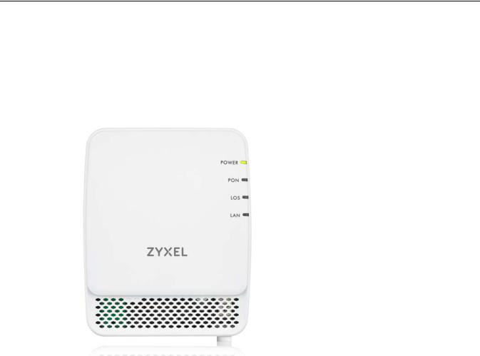
1.4.1 Front Panel
The following graphic displays the front panel of the GPON Device.
Figure 2 Front Panel
1.4.2 LEDs (Lights)
The following graphic displays the labels of the LEDs.
None of the LEDs are on if the GPON Device is not receiving power.
Table 1 LED Descriptions
|
LED |
COLOR |
STATUS |
|
DESCRIPTION |
|
|
|
|
|
|
|
POWER |
Green |
On |
|
The GPON Device is receiving power and is ready for use. |
|
|
|
|
|
|
|
|
|
Off |
|
The GPON Device is not receiving power. |
|
|
|
|
|
|
|
PON |
Green |
On |
|
The GPON Device has successful fiber link. |
|
|
|
|
|
|
|
|
|
Blinking |
|
The GPON Device’s PON port is syncing with OLT (fiber terminal). |
|
|
|
|
|
|
|
|
|
Off |
|
The GPON Device’s PON port is not connected. |
|
|
|
|
|
|
|
LOS |
Red |
On |
|
The GPON Device is not receiving an optical signal. |
|
|
|
|
|
|
|
|
|
Blinking |
|
The GPON Device is receiving a weak optical signal. |
|
|
|
|
|
|
|
|
|
Off |
|
The GPON Device is receiving a normal optical signal. |
|
|
|
|
|
|
|
LAN |
Green |
On |
|
The GPON Device has an Ethernet connection on the Local Area Network |
|
|
|
|
|
(LAN). |
|
|
|
|
|
|
|
|
|
Blinking |
|
The GPON Device is transmitting/receiving data on the Ethernet . |
|
|
|
|
|
|
|
|
|
Off |
|
The GPON Device does not have an Ethernet connection on the LAN. |
|
|
|
|
|
|
|
|
|
|
|
|
|
|
|
|
PMG1005-T20B User’s Guide |
|
7
Chapter 1 Introduction
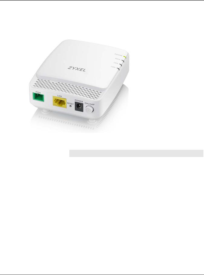
1.4.3 Bottom Panel
The following graphic displays the rear panel of the GPON Device.
Figure 3 Bottom Panel
The following table describes the items on the bottom panel.
Table 2 Rear Panel Ports
LABEL |
DESCRIPTION |
|
|
PON |
Connect a fiber optic cable to the PON port for Internet Access. |
|
|
LAN |
Connect a computer or another Ethernet device to the LAN port for Internet access. |
|
|
RESET |
Press the button to return the GPON Device to the factory defaults. |
|
|
POWER |
Connect the power cable (12V 0.5A) can press the ON/OFF button to start the |
|
device. |
|
|
1.5 The Reset Button
If you forget your password or cannot access the Web Configurator, you will need to use the RESET button at the back of the GPON Device to reload the factory-default configuration file. This means that you will lose all custom configuration and the password will be reset to the default.
1.5.1 Using the Reset Button
1Make sure the POWER LED is on (not blinking).
2To set the GPON Device back to the factory default settings (LAN IP address 192.168.1.1, user name admin and password 1234), press the RESET button for more than three seconds and then release it. The LEDs flash and the GPON Device restores the defaults and restarts.
PMG1005-T20B User’s Guide
8

Chapter 1 Introduction
Note: Press the RESET button for less than one second to restart the GPON Device without changing it back to the factory default settings.
1.6 Wall Mounting
You may need screw anchors if mounting on a concrete or brick wall.
Note: The screws and screw anchors are not included.
Table 3 Wall Mounting Information
Distance between holes |
54 mm |
|
|
M4.2 Screws |
Two |
|
|
Screw anchors (optional) |
Two |
|
|
1Select a position free of obstructions on a wall strong enough to hold the weight of the device.
2Mark two holes on the wall at the appropriate distance apart for the screws.
Be careful to avoid damaging pipes or cables located inside the wall when drilling holes for the screws.
3If using screw anchors, drill two holes for the screw anchors into the wall. Push the anchors into the full depth of the holes, then insert the screws into the anchors. Do not insert the screws all the way in - leave a small gap of about 0.5 cm.
If not using screw anchors, use a screwdriver to insert the screws into the wall. Do not insert the screws all the way in - leave a gap of about 0.5 cm
4Make sure the screws are fastened well enough to hold the weight of the GPON Device with the connection cables.
5Align the holes on the back of the GPON Device with the screws on the wall. Hang the GPON Device on the screws.
PMG1005-T20B User’s Guide
9

Chapter 1 Introduction
Figure 4 Wall Mounting Example
PMG1005-T20B User’s Guide
10
CHAPTER 2
The Web Configurator
2.1 Overview
The Web Configurator is an HTML-based management interface that allows easy GPON Device setup and management via Internet browser. You can use the following browsers:
•Internet Explorer 11.0 and later and later versions.
•Google Chrome 60.0.3112.113 and later versions.
•Mozilla Firefox 55.0.3 and later versions.
In order to use the Web Configurator you need to allow:
•Web browser pop-up windows from your GPON Device. Web pop-up blocking is enabled by default in Windows XP SP (Service Pack) 2.
•JavaScript (enabled by default).
•Java permissions (enabled by default).
2.1.1Accessing the Web Configurator
1Make sure your GPON Device hardware is properly connected (see the Quick Start Guide for details).
2Make sure your computer’s IP address is in the same subnet as the GPON Device. Check your computer’s help to see how to change your IP address.
3Launch your web browser.
4Type the default GPON Device address shown on the cover page of this User’s Guide as the URL.
5A login screen displays. Enter the user name and password shown on the cover page of this User’s Guide and click Login.
PMG1005-T20B User’s Guide
11
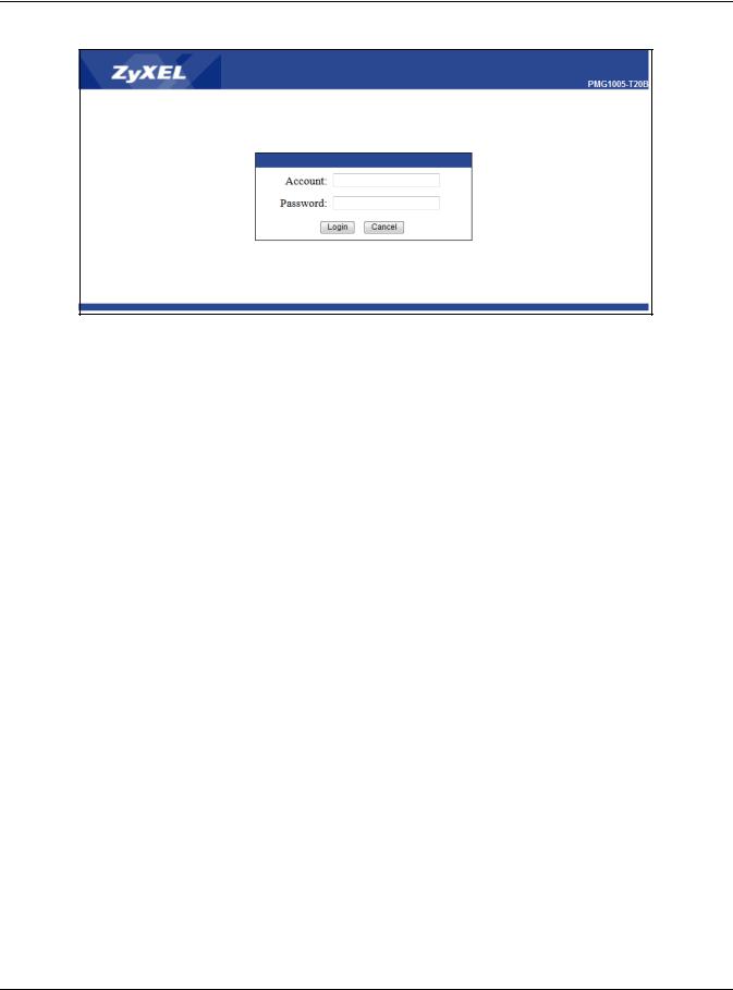
Chapter 2 The Web Configurator
Figure 5 Login Screen
Note: For security reasons, the GPON Device automatically logs you out if you do not use the Web Configurator for an extended period of time. If this happens, log in again.
2.2 Web Configurator Main Screen
The main screen is divided into these parts:
PMG1005-T20B User’s Guide
12
 Loading...