


 Loading...
User’s Guide
NSW Series
NSW100-10P / NSW100-10 / NSW100-28P / NSW100-28 / NSW200-28P
Nebula Cloud-Managed (PoE) Switch
Default Login Details |
|
|
|
Version 1.00 Edition 2, 04/2017 |
||||||||||||||||||||
|
|
|
|
|
|
|
|
|
|
|
|
|
||||||||||||
LAN IP Address |
|
|
http://DHCP-assigned IP or |
|
|
|
|
|
|
|
|
|||||||||||||
|
|
|
|
|
a configured static IP address |
|
|
|
|
|
|
|
|
|||||||||||
|
|
|
|
|
|
|
|
|
|
|
|
|
|
|
|
|
|
|
|
|||||
User name |
|
|
|
|
|
|
|
|
|
admin |
|
|
|
|
|
|
|
|
||||||
|
|
|
|
|
|
|
|
|
|
|
|
|
||||||||||||
Password |
|
|
Assigned by the NCC when |
|
|
|
|
|
|
|
|
|||||||||||||
|
|
|
|
|
the NSW is registered with the |
|
|
|
|
|
|
|
|
|||||||||||
|
|
|
|
|
|
|
|
|
|
|
|
|
NCC. |
|
|
|
|
|
|
|
|
|||
|
|
|
|
|
|
|
|
|
|
|
|
|
or |
|
|
|
|
|
|
|
|
|||
|
|
|
|
|
1234 |
|
|
|
|
|
|
|
|
|
|
|||||||||
|
|
|
|
|
|
|
|
|
|
|
|
|
|
|
|
|
|
|
|
|
|
|
|
|
|
|
|
|
|
|
|
|
|
|
|
|
|
|
|
|
|
|
|
|
|
|
|
|
|
|
|
|
|
|
|
|
|
|
|
|
|
|
|
|
|
|
|
|
|
|
|
|
|
|
|
|
|
|
|
|
|
|
|
|
|
|
|
|
|
|
|
|
|
|
|
|
|
|
|
|
|
|
|
|
|
|
|
|
|
|
|
|
|
|
|
|
|
|
|
|
|
|
|
|
|
|
|
|
|
|
|
|
|
|
|
|
|
|
|
|
|
|
|
|
|
|
|
|
|
|
|
|
|
|
|
|
|
|
|
|
|
|
|
|
|
|
|
|
|
|
|
|
|
|
|
|
|
|
|
|
|
|
|
|
|
|
|
|
|
|
|
|
|
|
|
|
|
|
|
|
|
|
|
|
|
|
|
|
|
|
|
|
|
|
|
|
|
|
|
|
|
|
|
|
|
|
|
|
|
|
|
|
|
|
|
|
|
|
|
|
|
|
|
|
|
|
|
|
|
|
|
|
|
|
|
|
|
|
|
|
|
|
|
|
|
|
|
|
|
|
|
|
|
|
|
|
|
|
|
|
|
|
|
|
|
|
|
|
|
|
|
|
|
|
|
|
|
|
|
|
|
|
|
|
|
|
|
|
|
|
|
|
|
|
|
|
|
|
|
|
|
|
|
|
Copyright © 2017 Zyxel Communications Corporation

IMPORTANT!
READ CAREFULLY BEFORE USE.
KEEP THIS GUIDE FOR FUTURE REFERENCE.
This is a User’s Guide for a system managing a series of products. Not all products support all features. Menushots and graphics in this book may differ slightly from what you see due to differences in release versions or your computer operating system. Every effort has been made to ensure that the information in this manual is accurate.
Related Documentation
•Quick Start Guide
The Quick Start Guide shows how to connect the managed device, such as the Nebula AP, gateway or security gateway.
•Online Help
Click the help link for a description of the fields in the NSW menus.
•More Information
Go to support.zyxel.com to find other information on the NSW.
NSW Series User’s Guide
2

Contents Overview |
|
|
Contents Overview |
User’s Guide ........................................................................................................................................ |
7 |
Getting to Know Your NSW .................................................................................................................... |
8 |
Hardware Installation and Connection ............................................................................................. |
13 |
Hardware Panels .................................................................................................................................. |
17 |
Technical Reference ........................................................................................................................ |
24 |
The Web Configurator ......................................................................................................................... |
25 |
Status ...................................................................................................................................................... |
30 |
Basic Setting .......................................................................................................................................... |
32 |
VLAN ...................................................................................................................................................... |
42 |
Maintenance ........................................................................................................................................ |
49 |
Diagnostic ............................................................................................................................................. |
58 |
Troubleshooting .................................................................................................................................... |
60 |
NSW Series User’s Guide
3

Table of Contents |
|
|
Table of Contents |
Contents Overview ............................................................................................................................. |
3 |
Table of Contents ................................................................................................................................. |
4 |
Part I: User’s Guide............................................................................................ |
7 |
Chapter 1 |
|
Getting to Know Your NSW.................................................................................................................. |
8 |
1.1 Introduction ....................................................................................................................................... |
8 |
1.1.1 Hardware Comparison ........................................................................................................... |
8 |
1.1.2 Management .......................................................................................................................... |
9 |
1.2 Applications ...................................................................................................................................... |
9 |
1.2.1 Backbone Application ........................................................................................................... |
9 |
1.2.2 Bridging Example .................................................................................................................. |
10 |
1.2.3 IEEE 802.1Q VLAN Application Examples ........................................................................... |
11 |
1.3 Ways to Manage the NSW ............................................................................................................ |
11 |
1.4 Good Habits for Managing the NSW ........................................................................................... |
12 |
Chapter 2 |
|
Hardware Installation and Connection ........................................................................................... |
13 |
2.1 Installation Scenarios ...................................................................................................................... |
13 |
2.2 Desktop Installation Procedure .................................................................................................... |
13 |
2.3 Mounting the NSW on a Rack ...................................................................................................... |
14 |
2.3.1 Rack-mounted Installation Requirements .......................................................................... |
14 |
2.3.2 Attaching the Mounting Brackets to the NSW ................................................................... |
14 |
2.3.3 Mounting the NSW on a Rack ............................................................................................. |
15 |
Chapter 3 |
|
Hardware Panels................................................................................................................................ |
17 |
3.1 Front Panel ...................................................................................................................................... |
17 |
3.1.1 Gigabit Ethernet Ports .......................................................................................................... |
17 |
3.1.2 PoE .......................................................................................................................................... |
18 |
3.1.3 Combo Port ........................................................................................................................... |
18 |
3.1.4 Transceiver Slots .................................................................................................................... |
19 |
3.1.5 Console Port .......................................................................................................................... |
20 |
3.2 Rear Panel ....................................................................................................................................... |
21 |
3.2.1 Power Connector ................................................................................................................. |
21 |
3.3 LEDs ................................................................................................................................................ |
22 |
NSW Series User’s Guide |
|
4

|
Table of Contents |
|
Part II: Technical Reference........................................................................... |
24 |
|
Chapter 4 |
|
|
The Web Configurator........................................................................................................................ |
25 |
|
4.1 |
Overview ......................................................................................................................................... |
25 |
4.2 |
System Login ................................................................................................................................... |
25 |
4.3 |
The Status Screen .......................................................................................................................... |
26 |
4.4 |
Saving Your Configuration ............................................................................................................. |
27 |
4.5 |
Switch Lockout ............................................................................................................................... |
28 |
4.6 |
Resetting the NSW ......................................................................................................................... |
28 |
4.7 |
Logging Out of the Web Configurator ....................................................................................... |
28 |
4.8 |
Help ................................................................................................................................................. |
29 |
Chapter 5 |
|
|
Status................................................................................................................................................... |
|
30 |
5.1 |
Status ................................................................................................................................................ |
30 |
Chapter 6 |
|
|
Basic Setting ....................................................................................................................................... |
32 |
|
6.1 |
Overview ......................................................................................................................................... |
32 |
|
6.1.1 What You Can Do ................................................................................................................. |
32 |
6.2 |
System Information ...................................................................................................................... |
32 |
6.3 |
IP Setup for NSW100 Series ............................................................................................................ |
34 |
6.4 |
IP Setup for NSW200-28P ................................................................................................................ |
35 |
|
6.4.1 Management IP Address ..................................................................................................... |
35 |
|
6.4.2 IP Status Details ...................................................................................................................... |
36 |
|
6.4.3 IP Configurations ................................................................................................................... |
37 |
6.5 |
Port Setup ....................................................................................................................................... |
39 |
6.6 |
DNS ................................................................................................................................................... |
41 |
Chapter 7 |
|
|
VLAN.................................................................................................................................................... |
|
42 |
7.1 |
Overview ......................................................................................................................................... |
42 |
|
7.1.1 What You Can Do ................................................................................................................. |
42 |
7.2 |
VLAN Status .................................................................................................................................... |
42 |
|
7.2.1 VLAN Details ......................................................................................................................... |
43 |
7.3 |
VLAN Configuration ...................................................................................................................... |
44 |
7.4 |
Configure a Static VLAN .............................................................................................................. |
44 |
7.5 |
Configure VLAN Port Settings ...................................................................................................... |
46 |
Chapter 8 |
|
|
Maintenance...................................................................................................................................... |
49 |
|
8.1 |
Overview ......................................................................................................................................... |
49 |
|
NSW Series User’s Guide |
|
5

|
Table of Contents |
|
|
8.1.1 What You Can Do ................................................................................................................. |
49 |
8.2 |
The Maintenance Screen ............................................................................................................ |
49 |
|
8.2.1 Erase Running-Configuration .............................................................................................. |
50 |
|
8.2.2 Save Configuration .............................................................................................................. |
51 |
|
8.2.3 Reboot System ...................................................................................................................... |
51 |
8.3 |
Firmware Upgrade ....................................................................................................................... |
52 |
8.4 |
Restore a Configuration File ....................................................................................................... |
53 |
8.5 |
Backup a Configuration File ........................................................................................................ |
54 |
8.6 |
Tech-Support .................................................................................................................................. |
54 |
8.7 |
Technical Reference ...................................................................................................................... |
55 |
|
8.7.1 FTP Command Line ............................................................................................................... |
55 |
|
8.7.2 Filename Conventions ......................................................................................................... |
55 |
|
8.7.3 FTP Command Line Procedure ........................................................................................... |
56 |
|
8.7.4 GUI-based FTP Clients ........................................................................................................... |
57 |
Chapter 9 |
|
|
Diagnostic........................................................................................................................................... |
58 |
|
9.1 |
Overview ......................................................................................................................................... |
58 |
9.2 |
Diagnostic ...................................................................................................................................... |
58 |
Chapter 10 |
|
|
Troubleshooting.................................................................................................................................. |
60 |
|
10.1 Power, Hardware Connections, and LEDs ................................................................................. |
60 |
|
10.2 NSW Access and Login ................................................................................................................ |
61 |
|
10.3 NSW Configuration ....................................................................................................................... |
62 |
|
Appendix A Customer Support ....................................................................................................... |
63 |
|
Appendix B Legal Information ......................................................................................................... |
69 |
|
Index ................................................................................................................................................... |
|
75 |
NSW Series User’s Guide
6

PART I
User’s Guide
7

CHAPTER 1
Getting to Know Your NSW
1.1 Introduction
This chapter introduces the main features and applications of the NSW. The NSW Series consists of the following models:
•NSW100-10P
•NSW100-10
•NSW100-28P
•NSW100-28
•NSW200-28P
1.1.1Hardware Comparison
The following is a hardware comparison table.
Table 1 The NSW Series Comparison Table
MODEL |
NSW100-10P |
NSW100-10 |
NSW100-28P |
NSW100-28 |
NSW200-28P |
||
|
|
|
|
|
|
||
Total Port Number |
10 |
10 |
28 |
28 |
28 |
||
|
|
|
|
|
|
||
10/100/1000Base-T |
- |
Ports 1-8 |
- |
Ports 1-24 |
- |
||
Port |
|||||||
|
|
|
|
|
|||
|
|
|
|
|
|
||
10/100/1000 Mbps |
Ports 1-8 |
- |
Ports 1-24 |
- |
Ports 1-24 |
||
PoE Port |
|||||||
|
|
|
|
|
|||
|
|
|
|
|
|
||
Combo Port |
|
|
|
|
|
||
• |
Gigabit Ports |
|
|
|
|
|
|
|
(Ethernet) |
Ports 9-10 |
Ports 9-10 |
Ports 25-28 |
Ports 25-28 |
- |
|
• |
Transceiver |
|
|
|
|
|
|
|
Slots (100/1000 |
|
|
|
|
|
|
|
Mbps SFP) |
|
|
|
|
|
|
|
|
|
|
|
|
||
Transceiver Slot |
|
|
|
|
|
||
1000 Mbps/10G |
- |
- |
- |
- |
Ports 25-28 |
||
(SFP+/DAC) |
|
|
|
|
|
||
|
|
|
|
|
|
||
Console Port |
Default baud rate |
Default baud rate |
- |
- |
Default baud rate |
||
|
|
115200bps |
115200 bps |
115200 bps |
|||
|
|
|
|
||||
|
|
|
|
|
|
||
PoE Maximum |
180W PoE power |
- |
375W PoE power |
- |
375W PoE power |
||
Power |
budget |
budget |
budget |
||||
|
|
||||||
|
|
|
|
|
|
|
|
See the Quick Start Guide for how to make hardware connections.
NSW Series User’s Guide
8
Chapter 1 Getting to Know Your NSW
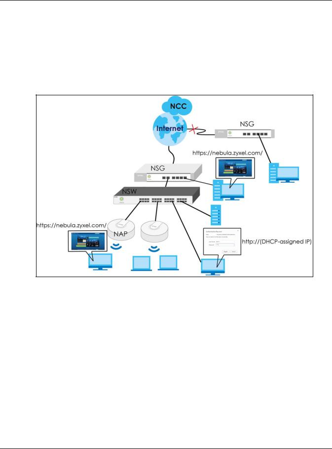
1.1.2 Management
The NSW needs an IP address for it to be managed over the network. The factory default IP address is DHCP Client. To find the DHCP-assigned IP address, you must use the NCC, the ZON utility, or the console port.
The NSW is a Nebula cloud-managed (PoE) switch. It is managed and provisioned by the NCC (Nebula Control Center) when it is connected to the Internet and registered with the NCC.
Figure 1 NCC Management Example
You can check the system settings via the Web Configurator, the ZON (Zyxel One Network) utility and the console port.
1.2 Applications
This section shows a few examples of using the NSW in various network environments.
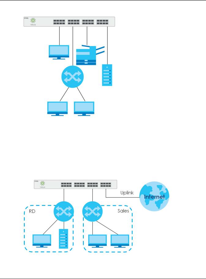
1.2.1 Backbone Application
The NSW is an ideal solution for small networks where rapid growth can be expected in the near future. The NSW can be used standalone for a group of heavy traffic users. You can connect computers and servers directly to the NSW’s port or connect other switches to the NSW.
In this example, all computers can share high-speed applications on the server. To expand the network, simply add more networking devices such as switches, routers, computers, print servers etc.
NSW Series User’s Guide
9
Chapter 1 Getting to Know Your NSW
Figure 2 Backbone Application
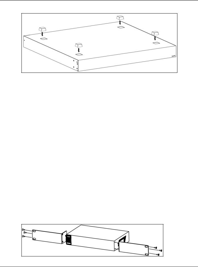
1.2.2 Bridging Example
In this example, the NSW connects different company departments (RD and Sales) to the corporate backbone. It can alleviate bandwidth contention and eliminate server and network bottlenecks. All users that need high bandwidth can connect to high-speed department servers via the NSW. You can provide a super-fast uplink connection by using a Gigabit Ethernet/mini-GBIC port on the NSW.
Moreover, the NSW eases supervision and maintenance by allowing network managers to centralize multiple servers at a single location.
Figure 3 Bridging Application
NSW Series User’s Guide
10
Chapter 1 Getting to Know Your NSW
1.2.3 IEEE 802.1Q VLAN Application Examples
A VLAN (Virtual Local Area Network) allows a physical network to be partitioned into multiple logical networks. Stations on a logical network belong to one group. A station can belong to more than one group. With VLAN, a station cannot directly talk to or hear from stations that are not in the same group(s) unless such traffic first goes through a router.
For more information on VLANs, refer to Chapter 7 on page 42.
1.2.3.1 Tag-based VLAN Example
Ports in the same VLAN group share the same frame broadcast domain thus increase network performance through reduced broadcast traffic. VLAN groups can be modified at any time by adding, moving or changing ports without any re-cabling.
Shared resources such as a server can be used by all ports in the same VLAN as the server. In the following figure only ports that need access to the server need to be part of VLAN 1. Ports can belong to other VLAN groups too.
Figure 4 Shared Server Using VLAN Example
1.3 Ways to Manage the NSW
Use any of the following methods to manage the NSW.
•NCC. With the NCC, you can remotely manage and monitor the NSW through a cloud-based network management system. See the NCC User’s Guide for detailed information about how to access the NCC and manage your NSW via the NCC.
•Web Configurator. This is recommended for everyday management of the NSW using a (supported) web browser. See Chapter 4 on page 25.
•Command Line Interface. You can use commands to see the system settings.
•FTP. Use FTP for firmware upgrades and configuration backup/restore. See Section 8.7.1 on page 55.
NSW Series User’s Guide
11

Chapter 1 Getting to Know Your NSW
1.4 Good Habits for Managing the NSW
Do the following things regularly to make the NSW more secure and to manage the NSW more effectively.
•Change the NSW’s password through the NCC occasionally. Use a password that’s not easy to guess and that consists of different types of characters, such as numbers and letters.
•Write down the password and put it in a safe place.
•Back up the configuration (and make sure you know how to restore it). Restoring an earlier working configuration may be useful if the device becomes unstable or even crashes. If you forget your password, you will have to reset the NSW to its factory default settings. If you backed up an earlier configuration file, you would not have to totally re-configure the NSW. You could simply restore your last configuration.
NSW Series User’s Guide
12

CHAPTER 2
Hardware Installation and
Connection
2.1 Installation Scenarios
This chapter shows you how to install and connect the NSW.
The NSW can be placed on a desktop or rack-mounted on a standard EIA rack. Use the rubber feet in a desktop installation and the brackets in a rack-mounted installation.
Note: For proper ventilation, allow at least 4 inches (10 cm) of clearance at the front and 3.4 inches (8 cm) at the back of the NSW. This is especially important for enclosed rack installations.
2.2 Desktop Installation Procedure
1Make sure the NSW is clean and dry.
2Set the NSW on a smooth, level surface strong enough to support the weight of the NSW and the connected cables. Make sure there is a power outlet nearby.
3Make sure there is enough clearance around the NSW to allow air circulation and the attachment of cables and the power cord.
4Remove the adhesive backing from the rubber feet.
5Attach the rubber feet to each corner on the bottom of the NSW. These rubber feet help protect the NSW from shock or vibration and ensure space between devices when stacking.
Note: Do NOT block the ventilation holes.
NSW Series User’s Guide
13
Chapter 2 Hardware Installation and Connection
Figure 5 Attaching Rubber Feet
2.3 Mounting the NSW on a Rack
The NSW can be mounted on an EIA standard size, 19-inch rack or in a wiring closet with other equipment.
Follow the steps below to mount your NSW on a standard EIA rack using a rack-mounting kit.
2.3.1Rack-mounted Installation Requirements
•Two mounting brackets.
•Eight M3 flat head screws and a #2 Philips screwdriver.
•Four M5 flat head screws and a #2 Philips screwdriver.
Failure to use the proper screws may damage the unit.
2.3.1.1Precautions
•Make sure the rack will safely support the combined weight of all the equipment it contains.
•Make sure the position of the NSW does not make the rack unstable or top-heavy. Take all necessary precautions to anchor the rack securely before installing the unit.
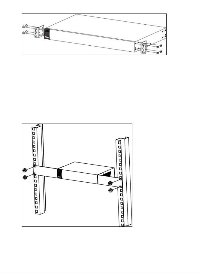
2.3.2Attaching the Mounting Brackets to the NSW
1Position a mounting bracket on one side of the NSW, lining up the four screw holes on the bracket with the screw holes on the side of the NSW.
Figure 6 Attaching the Mounting Brackets (NSW100-10P and NSW100-10)
NSW Series User’s Guide
14
Chapter 2 Hardware Installation and Connection
Figure 7 Attaching the Mounting Brackets (NSW100-28P, NSW100-28 and NSW200-28P)
2Using a #2 Philips screwdriver, install the M3 flat head screws through the mounting bracket holes into the NSW.
3Repeat steps 1 and 2 to install the second mounting bracket on the other side of the NSW.
4You may now mount the NSW on a rack. Proceed to the next section.
2.3.3Mounting the NSW on a Rack
1Position a mounting bracket (that is already attached to the NSW) on one side of the rack, lining up the two screw holes on the bracket with the screw holes on the side of the rack.
Figure 8 Mounting the NSW on a Rack (NSW100-10P and NSW100-10)
NSW Series User’s Guide
15
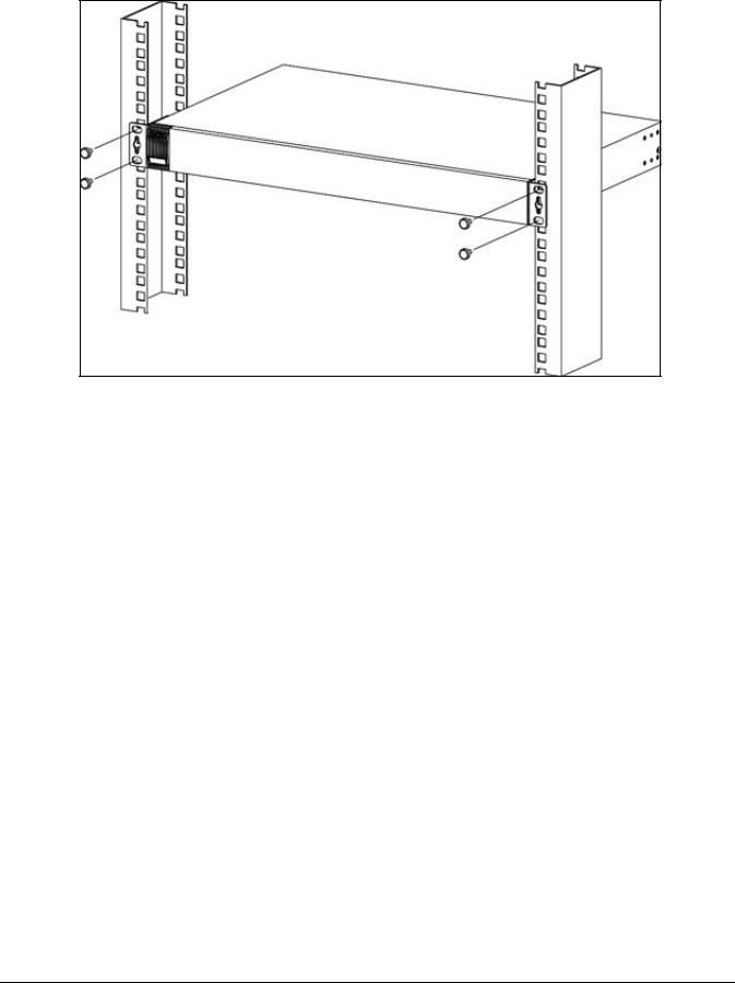
Figure 9 Mounting the NSW on a Rack (NSW100-28P, NSW100-28 and NSW200-28P)
2Using a #2 Philips screwdriver, install the M5 flat head screws through the mounting bracket holes into the rack.
3Repeat steps 1 and 2 to attach the second mounting bracket on the other side of the rack.
Note: Make sure you tighten all the four screws to prevent the NSW from getting slanted.
NSW Series User’s Guide
16

Chapter 3 Hardware Panels
CHAPTER 3
Hardware Panels
This chapter describes the front panel and rear panel of the Switch and shows you how to make the hardware connections.
See Table 1 on page 8, for detailed information about port features of the NSW Series.
3.1 Front Panel
The following figures show the front panels of the NSW.
Figure 10 Front Panel: NSW100-10P
Figure 11 Front Panel: NSW100-10
Figure 12 Front Panel: NSW100-28P
Figure 13 Front Panel: NSW100-28
Figure 14 Front Panel: NSW200-28P
3.1.1 Gigabit Ethernet Ports
See Table 1 on page 8, for detailed information about port features of the NSW Series.
NSW Series User’s Guide
17

Chapter 3 Hardware Panels
The NSW has 1000Base-T auto-negotiating, auto-crossover Ethernet ports. In 10/100/1000 Mbps Gigabit Ethernet, the speed can be 10 Mbps, 100 Mbps or 1000 Mbps. The duplex mode can be half duplex or full duplex.
An auto-negotiating port can detect and adjust to the optimum Ethernet speed (10/100/1000 Mbps) and duplex mode (full duplex or half duplex) of the connected device.
An auto-crossover (auto-MDI/MDI-X) port automatically works with a straight-through or crossover Ethernet cable.
When auto-negotiation is turned on, an Ethernet port negotiates with the peer automatically to determine the connection speed and duplex mode. If the peer Ethernet port does not support autonegotiation or turns off this feature, the NSW determines the connection speed by detecting the signal on the cable and using half duplex mode. When the NSW’s auto-negotiation is turned off, an Ethernet port uses the pre-configured speed and duplex mode when making a connection, thus requiring you to make sure that the settings of the peer Ethernet port are the same in order to connect.
3.1.1.1 Default Ethernet Negotiation Settings
The factory default negotiation settings for the Gigabit ports on the NSW are:
•Speed: Auto
•Duplex: Auto
•Flow control: Off
•Link Aggregation: Disabled
3.1.1.2Auto-crossover
All ports are auto-crossover, that is auto-MDIX ports (Media Dependent Interface Crossover), so you may use either a straight-through Ethernet cable or crossover Ethernet cable for all Gigabit port connections. Auto-crossover ports automatically sense whether they need to function as crossover or straight ports, so crossover cables can connect both computers and switches/hubs.
3.1.2 PoE
The NSW supports both the IEEE 802.3af Power over Ethernet (PoE) and IEEE 802.3at Power over Ethernet (PoE) plus standards. The NSW is a Power Sourcing Equipment (PSE) because it provides a source of power via its Ethernet ports. Each device that receives power through an Ethernet port is a Powered Device (PD).
See Table 1 on page 8 for detailed information about PoE maximum power of each model.
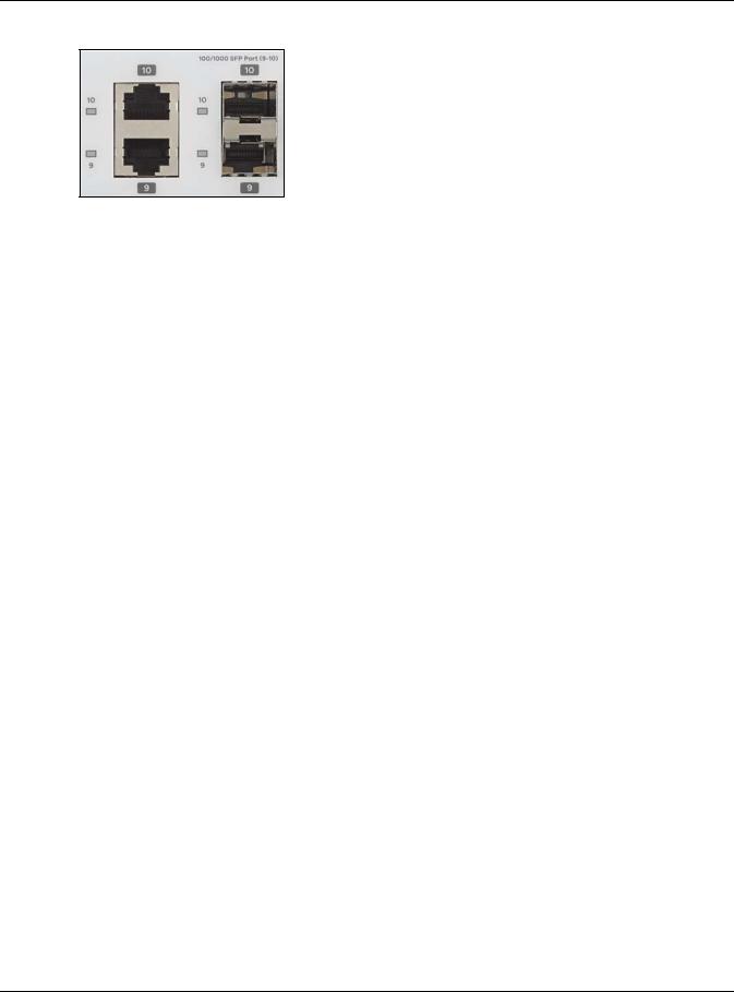
3.1.3 Combo Port
A combo port is for uplink connections. It consists of a Gigabit Ethernet port for Ethernet connection, and a transceiver slot for fiber connection. The fiber connection takes priority if the corresponding Gigabit port is also connected.
•10/100/1000 Mbps Gigabit Ports - Connect these ports to high-bandwidth backbone network Ethernet switches using 1000BASE-T compatible Category 5/5e/6 copper cables.
•Transceiver Slots - Use SFP in these slots for connections to backbone Ethernet switches.
NSW Series User’s Guide
18
Chapter 3 Hardware Panels
Figure 15 Combo Port Example: Gigabit Port and Transceiver Slot
3.1.4 Transceiver Slots
See Section 3.1.3 on page 18, for more information about combo ports.
The transceiver slots are for Small Form-Factor Pluggable (SFP), SFP+ transceivers or DAC cable. The SFP+ (SFP Plus) and the DAC cable are enhanced versions of the SFP and support data rates of up to 10 Gbps. A transceiver is a single unit that houses a transmitter and a receiver. Use a transceiver or a DAC cable to connect a fiber-optic cable to the NSW. The NSW does not come with transceivers nor DAC cables. You must use transceivers or DAC cables that comply with the Small Form-factor Pluggable (SFP) Transceiver MultiSource Agreement (MSA). See the SFF committee’s INF-8074i specification Rev 1.0 for details.
You can change transceivers or the DAC cables while the NSW is operating. You can use different transceivers to connect to Ethernet switches with different types of fiber-optic connectors.
•Type: SFP connection interface
Connection speed: 100/1000 Megabit per second (Mbps)
•Type: SFP+/DAC connection interface
Connection speed: 1 or 10 Gigabit per second (Gbps)
To avoid possible eye injury, do not look into an operating fiber-optic module’s connectors.
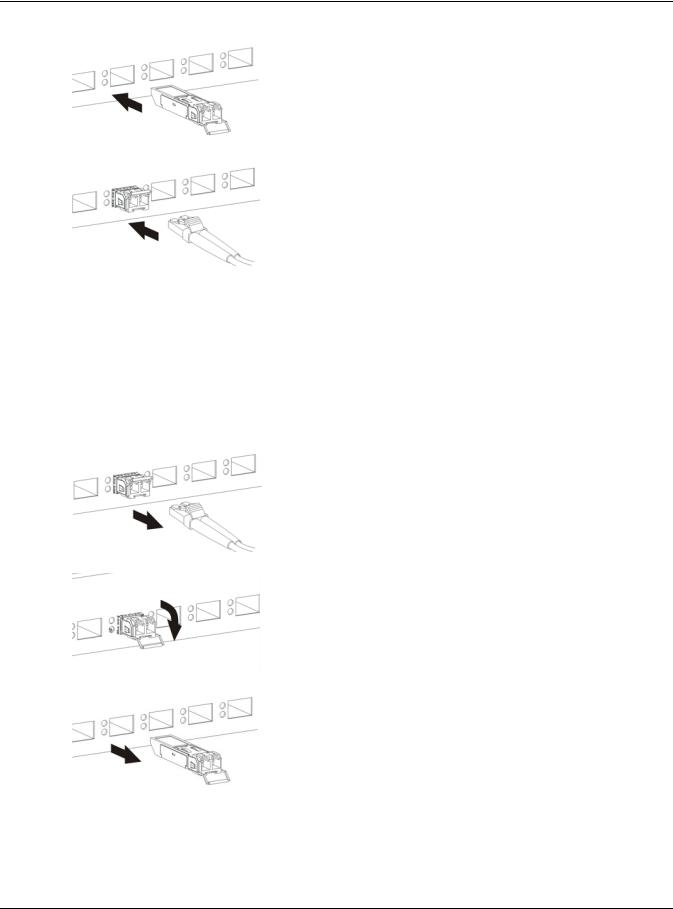
3.1.4.1 Transceiver Installation
Use the following steps to install a mini-GBIC transceiver (SFP module).
1Insert the transceiver into the slot with the exposed section of PCB board facing down.
2Press the transceiver firmly until it clicks into place.
3The NSW automatically detects the installed transceiver. Check the LEDs to verify that it is functioning properly.
4Close the transceiver’s latch (latch styles vary).
5Connect the fiber optic cables to the transceiver.
NSW Series User’s Guide
19
Chapter 3 Hardware Panels
Figure 16 Transceiver Installation Example
Figure 17 Connecting the Fiber Optic Cables
3.1.4.2 Transceiver Removal
Use the following steps to remove a mini-GBIC transceiver (SFP module).
1Remove the fiber optic cables from the transceiver.
2Open the transceiver’s latch (latch styles vary).
3Pull the transceiver out of the slot.
Figure 18 Removing the Fiber Optic Cables
Figure 19 Opening the Transceiver’s Latch Example
Figure 20 Transceiver Removal Example
3.1.5Console Port
To see system settings, such as system information, VLAN status, etc., you can use a computer with terminal emulation software configured to the following parameters:
NSW Series User’s Guide
20
Chapter 3 Hardware Panels
•VT100
•Terminal emulation
•115200 bps (NSW200-28P) or 9600 bps (NSW100-10P)
•No parity, 8 data bits, 1 stop bit
•No flow control
Connect the male 9-pin end of the console cable to the console port of the NSW. Connect the female end to a serial port (COM1, COM2 or other COM port) of your computer.
3.2 Rear Panel
The following figures show the rear panels of the NSW.
Figure 21 Rear Panel: NSW100-10P
Figure 22 Rear Panel: NSW100-10
Figure 23 Rear Panel: NSW100-28P
Figure 24 Rear Panel: NSW100-28
Figure 25 Rear Panel: NSW200-28P
3.2.1 Power Connector
Note: Make sure you are using the correct power source as shown on the panel.
To connect power to the NSW, insert the female end of the power cord to the AC power receptacle on the rear panel. Connect the other end of the supplied power cord to a power outlet. Make sure that no objects obstruct the airflow of the fans (located on the side of the unit).
See Chapter 10 on page 60 for information on the NSW’s power supply requirements.
NSW Series User’s Guide
21

Chapter 3 Hardware Panels
3.3 LEDs
After you connect the power to the NSW, view the LEDs to ensure proper functioning of the NSW and as an aid in troubleshooting.
Note: Please refer to Nebula Device Startup LED Guide, for more information about the system and locator LEDs when they light up at the same time.
The following table is for NSW100 Series.
Table 2 LED Descriptions for NSW100 Series
LED |
COLOR |
STATUS |
DESCRIPTION |
|
|
|
|
|
|
PWR |
Green |
On |
The system is turned on. |
|
|
|
|
|
|
|
|
Off |
The system is off or has failed. |
|
|
|
|
|
|
SYS |
Green |
On |
The system is on and functioning properly. The NSW can connect to the |
|
|
|
|
Nebula Control Center. |
|
|
|
|
|
|
|
|
Blinking |
The system is rebooting and performing self-diagnostic tests. |
|
|
|
|
If the system LED is blinking green with the alarm LED blinking red, it means the |
|
|
|
|
NSW cannot connect to the Nebula Control Center. |
|
|
|
|
|
|
|
|
Off |
The power is off or the system is not ready/malfunctioning. |
|
|
|
|
|
|
ALM |
Red |
On |
The system is having a hardware failure, such as high device temperature, |
|
|
|
|
wrong voltage, or abnormal fan speed. |
|
|
|
|
|
|
|
|
Blinking |
If the alarm LED is blinking red with the system LED blinking green, it means the |
|
|
|
|
NSW cannot connect to the Nebula Control Center. |
|
|
|
|
|
|
|
|
Off |
The system is functioning normally. |
|
|
|
|
|
|
Locator |
Blue |
Blinking |
Shows the actual location of the NSW between several devices in a rack. The |
|
|
|
|
default timer is 30 minutes when you are configuring the NSW. |
|
|
|
|
|
|
|
|
Off |
The locator is not functioning or malfunctioning. |
|
|
|
|
|
|
10/100/1000Base-T Ports |
|
|
||
|
|
|
|
|
1-8 (NSW100- |
Green |
On |
The link to a 10 Mbps or a 1000 Mbps Ethernet network is up. |
|
10P/NSW100-10) |
|
|
|
|
|
Blinking |
The system is transmitting/receiving to/from a 10 Mbps or a 1000 Mbps |
||
|
|
|||
1-24 (NSW100- |
|
|
Ethernet network. |
|
28P/NSW100-28) |
|
|
|
|
Amber |
On |
The link to a 100 Mbps Ethernet network is up. |
||
|
||||
LNK/ACT |
|
|
|
|
|
Blinking |
The system is transmitting/receiving to/from a 100 Mbps Ethernet network. |
||
|
|
|
|
|
|
|
Off |
The Ethernet link is down. |
|
|
|
|
|
|
PoE 10/100/1000Base-T Ports |
|
|
||
|
|
|
|
|
1-8 (NSW100- |
Green |
On |
Power supplied to all PoE Ethernet ports meets the IEEE 802.3at standard. |
|
10P) |
|
|
|
|
Amber |
On |
Power supplied to all PoE Ethernet ports meets the IEEE 802.3af standard. |
||
|
||||
1-24 (NSW100- |
|
|
|
|
|
Off |
The PoE is off or the Ethernet link is down. |
||
28P) |
|
|||
|
|
|
||
PoE |
|
|
|
|
|
|
|
|
|
100/1000 Mbps SFP Slots |
|
|
||
|
|
|
|
|
NSW Series User’s Guide
22

|
|
|
Chapter 3 Hardware Panels |
|
|
|
|
|
|
Table 2 LED Descriptions for NSW100 Series (continued) |
||||
LED |
COLOR |
STATUS |
|
DESCRIPTION |
|
|
|
|
|
9-10 (NSW100- |
Green |
On |
|
The port has a successful 1000 Mbps connection. |
10P/NSW100- |
|
|
|
|
|
Blinking |
|
The port is transmitting or receiving data at 1000 Mbps. |
|
10)) |
|
|
||
|
|
|
|
|
25-28 (NSW100- |
Amber |
On |
|
The port has a successful 100 Mbps connection. |
|
|
|
|
|
|
Blinking |
|
The port is transmitting or receiving data at 100 Mbps. |
|
28P/NSW100-28) |
|
|
||
|
|
|
|
|
LNK/ACT |
|
Off |
|
This link is disconnected. |
|
|
|
|
|
|
|
|
|
|
The following table is for NSW200-28P.
Table 3 LED Descriptions for NSW200-28P
LED |
COLOR |
STATUS |
DESCRIPTION |
|
|
|
|
PWR |
Green |
On |
The system is turned on. |
|
|
|
|
|
|
Off |
The system is off or has failed. |
|
|
|
|
SYS |
Green |
On |
The system is on and functioning properly. The NSW can connect to the |
|
|
|
Nebula Control Center. |
|
|
|
|
|
|
Blinking |
The system is rebooting and performing self-diagnostic tests. |
|
|
|
|
|
|
Off |
The power is off or the system is not ready/malfunctioning. |
|
|
|
|
FAN |
Green |
On |
The fan is functioning properly. |
|
|
|
|
|
Amber |
On |
The fan is not functioning at a proper speed or malfunctioning. |
|
|
|
|
PoE MAX |
Green |
On |
PoE power usage is over 80 percent of the power supplied budget, but |
|
|
|
below 95 percent of the power supplied budget. |
|
|
|
|
|
Amber |
On |
PoE power usage is more than 95 percent of the power supplied budget. |
|
|
|
|
|
|
Off |
PoE power usage is below 80 percent of the power supplied budget. |
|
|
|
|
Locator |
Blue |
Blinking |
Shows the actual location of the NSW between several devices in a rack. The |
|
|
|
default timer is 30 minutes when you are configuring the NSW. |
|
|
|
|
|
|
Off |
The locator is not functioning or malfunctioning. |
|
|
|
|
10/100/1000Base-T Ports |
|
|
|
|
|
|
|
1-24 LNK/ACT |
Green |
On |
The link to a 10 Mbps or a 1000 Mbps Ethernet network is up. |
(Left) |
|
|
|
|
Blinking |
The system is transmitting/receiving to/from a 10 Mbps or a 1000 Mbps |
|
|
|
||
|
|
|
Ethernet network. |
|
|
|
|
|
Amber |
On |
The link to a 100 Mbps Ethernet network is up. |
|
|
|
|
|
|
Blinking |
The system is transmitting/receiving to/from a 100 Mbps Ethernet network. |
|
|
|
|
|
|
Off |
The Ethernet link is down. |
|
|
|
|
PoE 10/100/1000Base-T Ports |
|
|
|
|
|
|
|
1-24 PoE (Right) |
Green |
On |
Power supplied to all PoE Ethernet ports meets the IEEE 802.3at standard. |
|
|
|
|
|
Amber |
On |
Power supplied to all PoE Ethernet ports meets the IEEE 802.3af standard. |
|
|
|
|
|
|
Off |
The PoE is off or the Ethernet link is down. |
|
|
|
|
1000 Mbps/10G SFP+ Slots |
|
|
|
|
|
|
|
25-28 LNK/ACT |
Green |
On |
The port has a successful 1000 Mbps connection. |
|
|
|
|
|
|
Blinking |
The port is transmitting or receiving data at 1000 Mbps. |
|
|
|
|
|
Blue |
On |
The port has a successful 10 Gbps connection. |
|
|
|
|
|
|
Blinking |
The port is transmitting or receiving data at 10 Gbps. |
|
|
|
|
|
|
Off |
This link is disconnected. |
|
|
|
|
NSW Series User’s Guide
23

PART II
Technical Reference
24
Loading...