

NBG5715
Simultaneous Dual-Band Wireless N Media Router
Default Login Details
IP Address http://192.168.1.1
Password 1234
Firmware Version 1.0
Edition 1, 3/2011
www.zyxel.com
www.zyxel.com
Copyright © 2011
ZyXEL Communications Corporation


About This User's Guide
About This User's Guide
Intended Audience
This manual is intended for people who want to configure the NBG5715 using the Web Configurator.
You should have at least a basic knowledge of TCP/IP networking concepts and topology.
Tips for Reading User’s Guides On-Screen
When reading a ZyXEL User’s Guide On-Screen, keep the following in mind:
• If you don’t already have the latest version of Adobe Reader, you can download it from http://
www.adobe.com.
• Use the PDF’s bookmarks to quickly navigate to the areas that interest you. Adobe Reader’s
bookmarks pane opens by default in all ZyXEL User’s Guide PDFs.
• If you know the page number or know vaguely which page-range you want to view, you can
enter a number in the toolbar in Reader, then press [ENTER] to jump directly to that page.
• Type [CTRL]+[F] to open the Adobe Reader search utility and enter a word or phrase. This can
help you quickly pinpoint the information you require. You can also enter text directly into the
toolbar in Reader.
• To quickly move around within a page, press the [SPACE] bar. This turns your cursor into a
“hand” with which you can grab the page and move it around freely on your screen.
• Embedded hyperlinks are actually cross-references to related text. Click them to jump to the
corresponding section of the User’s Guide PDF.
Related Documentation
•Quick Start Guide
The Quick Start Guide is designed to help you get your NBG5715 up and running right away. It
contains information on setting up your network and configuring for Internet access.
•Support Disc
Refer to the included CD for support documents.
Documentation Feedback
Send your comments, questions or suggestions to: techwriters@zyxel.com.tw
Thank you!
The Technical Writing Team, ZyXEL Communications Corp.,
6 Innovation Road II, Science-Based Industrial Park, Hsinchu, 30099, Taiwan.
NBG5715 User’s Guide
3
About This User's Guide
Need More Help?
More help is available at www.zyxel.com.
• Download Library
Search for the latest product updates and documentation from this link. Read the Tech Doc
Overview to find out how to efficiently use the User Guide, Quick Start Guide and Command Line
Interface Reference Guide in order to better understand how to use your product.
•Knowledge Base
If you have a specific question about your product, the answer may be here. This is a collection
of answers to previously asked questions about ZyXEL products.
•Forum
This contains discussions on ZyXEL products. Learn from others who use ZyXEL products and
share your experiences as well.
Customer Support
Should problems arise that cannot be solved by the methods listed above, you should contact your
vendor. If you cannot contact your vendor, then contact a ZyXEL office for the region in which you
bought the device.
See http://www.zyxel.com/web/contact_us.php for contact information. Please have the following
information ready when you contact an office.
• Product model and serial number.
• Warrant y Information.
• Date that you received your device.
4
NBG5715 User’s Guide

Document Conventions
Document Conventions
Warnings and Notes
These are how warnings and notes are shown in this User’s Guide.
Warnings tell you about things that could harm you or your device.
Note: Notes tell you other important information (for example, other things you may
need to configure or helpful tips) or recommendations.
Syntax Conventions
• The NBG5715 may be referred to as the “NBG5715”, the “device”, the “product” or the “system”
in this User’s Guide.
• Product labels, screen names, field labels and field choices are all in bold font.
• A key stroke is denoted by square brackets and uppercase text, for example, [ENTER] means the
“enter” or “return” key on your keyboard.
• “Enter” means for you to type one or more characters and then press the [ENTER] key. “Select”
or “choose” means for you to use one of the predefined choices.
• A right angle bracket ( > ) within a screen name denotes a mouse click. For example,
Maintenance > Log > Log Setting means you first click Maintenance in the navigation panel,
then the Log sub menu and finally the Log Setting tab to get to that screen.
• Units of measurement may denote the “metric” value or the “scientific” value. For example, “k”
for kilo may denote “1000” or “1024”, “M” for mega may denote “1000000” or “1048576” and so
on.
• “e.g.,” is a shorthand for “for instance”, and “i.e.,” means “that is” or “in other words”.
NBG5715 User’s Guide
5
Document Conventions
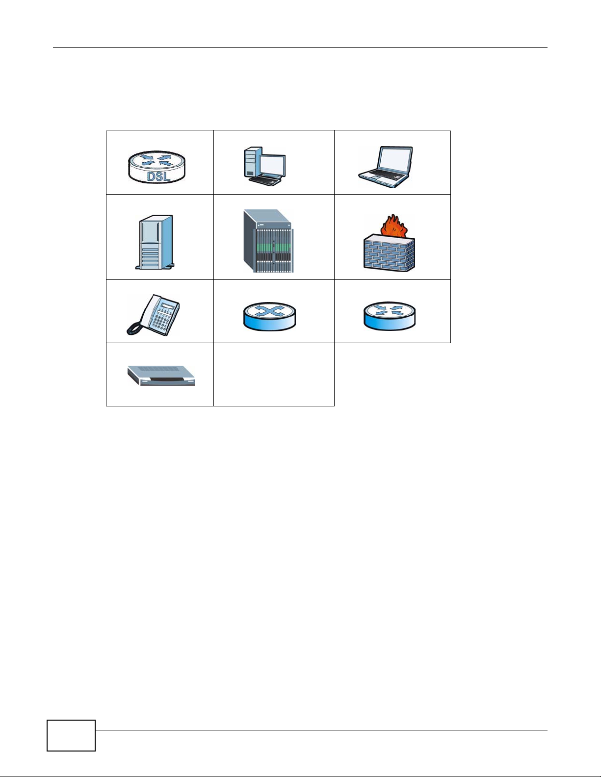
Icons Used in Figures
Figures in this User’s Guide may use the following generic icons. The NBG5715 icon is not an exact
representation of your device.
NBG5715 Computer Notebook computer
Server DSLAM Firewall
Telephone Switch Router
Modem
6
NBG5715 User’s Guide

Safety Warnings
Safety Warnings
• Do NOT use this product near water, for example, in a wet basement or near a swimming pool.
• Do NOT expose your device to dampness, dust or corrosive liquids .
• Do NOT store things on the device.
• Do NOT install, use, or service this device during a thunderstorm. There is a remote risk of electric shock
from lightning.
• Connect ONLY suitable accessories to the device.
• Do NOT open the device or unit. Opening or removing covers can expose you to dangerous high voltage
points or other risks. ONLY qualified service personnel should service or disassemble this device. Please
contact your vendor for further information.
• Make sure to connect the cables to the correct ports.
• Place connecting cables carefully so that no one will step on them or stumble over them.
• Always disconnect all cables from this device before servicing or disassembling.
• Use ONLY an appropriate power adaptor or cord for your device.
• Connect the power adaptor or cord to the right supply voltage (for example, 110V AC in North America or
230V AC in Europe).
• Do NOT allow anything to rest on the power adaptor or cord and do NOT place the pro duct where an yone can
walk on the power adaptor or cord.
• Do NOT use the devi ce if the power adaptor or cord is damaged as it might cause electrocution.
• If the power adaptor or cord is damaged, remove it from the power outlet.
• Do NOT attempt to repair the power adaptor or cord. Contact your local vendor to order a new one.
• Do no t use the device outside, and make sure all the connections are indoors. There i s a remote risk of
electric shock from lightning.
• Do NOT obstruct the devi ce ventilation slots, as insufficient airflow may harm your device.
• Antenna Warning! This device meets ETSI and FCC certification requirements when using the inc luded
antenna(s). Only use the included antenna(s).
• If you wall mount your device, make sure that no electrical lines, gas or water pipes will be damaged.
• This product is for indoor use only (utilisat ion i ntérieure exclusivement).
Your product is mark ed with this symbol, wh ich is known as the WEEE mark. WEEE stan ds for
Waste Electronics and Electrical Equipment. It means that used electrical and electronic
products should not be mixed with general waste. Used electrical and electronic equipment
should be treated separately.
NBG5715 User’s Guide
7

Safety Warnings
8
NBG5715 User’s Guide

Contents Overview
Contents Overview
User’s Guide ...........................................................................................................................19
Introduction ................................................................................................................................21
The WPS Button ........................................................................................................................25
ZyXEL NetUSB Share Center Utility ..........................................................................................26
Introducing the Web Configurator ..............................................................................................33
Monitor and Summary ..... ...........................................................................................................37
NBG5715 Modes ................................ .... ... ... ... ... .... ... .................................................................43
Easy Mode .................................................................................................................................44
Router Mode ..............................................................................................................................55
Tutorials .....................................................................................................................................61
Technical Reference ..............................................................................................................69
WAN ....................................................... ...................................................... ..............................71
Wireless LAN ..... ... ... .... ... ... ... .............................................. ... ... ... .... ... ... ....................................79
LAN ............................................................................................................................................95
DHCP Server .............................................................................................................................99
NAT ..........................................................................................................................................103
Dynamic DNS ........................................................................................................................... 113
Static Route .............................................................................................................................. 115
Firewall ...................................... ................................ ................................... ............................119
IPSec VPN ......................................... .... ... ............................................. ... ... .... ... ... ..................124
Bandwidth Management .... ... .... ... ... ... .... ... ... ... ... ................................................. ... ... .... ........... 147
Remote Management ...............................................................................................................152
Universal Plug-and-Play (UPnP) ..............................................................................................155
Maintenance .................................... ....... ...... ...... ....... ...... ....... ...... ....... ...... ....... ... ...... ...............163
Troubleshooting .......................................................................................................................171
NBG5715 User’s Guide
9

Contents Overview
10
NBG5715 User’s Guide

Table of Contents
Table of Contents
About This User's Guide..........................................................................................................3
Document Conventions ...........................................................................................................5
Safety Warnings........................................................................................................................7
Contents Overview...................................................................................................................9
Table of Contents ...................................................................................................................11
Part I: User’s Guide ................................................................................19
Chapter 1
Introduction.............................................................................................................................21
1.1 Overview ................................... ... .............................................. ... ... ... ... .... ... .......................21
1.2 Applications ............................................ ... ... .... ... ... ... .............................................. .............22
1.3 Ways to Manage the NBG5715 .......................................... ... .... ... ... ... ... .... ... .......................22
1.4 Good Habits for Managing the NBG5715 ............................................................................22
1.5 LEDs .. .... ... ... ... ... .............................................. ... ... ... .... .......................................................23
Chapter 2
The WPS Button......................................................................................................................25
2.1 Overview ................................... ... .............................................. ... ... ... ... .... ... .......................25
Chapter 3
ZyXEL NetUSB Share Center Utility......................................................................................26
3.1 Overview ................................... ... .............................................. ... ... ... ... .... ... .......................26
3.1.1 Quick Setup ............................................ ... ... ... .... ... ............................................. ... ....26
3.1.2 Installing ZyXEL NetUSB Share Center Utility ............................................................26
3.2 The ZyXEL NetUSB Share Center Utility .............................................................................27
3.2.1 The Menus ................. ... ... ... .............................................. ... ... ... ... .... ... ... ... .... ... ..........28
3.2.2 The Share Center Configuration Window ...................................................................29
3.2.3 The Auto-Connect Printer List Window ......................................................................29
3.3 Manually Connecting to USB Devices .................................................................................30
3.4 Automatically Connecting to a USB Printer ................................... ... ... ... .... ... ... ... .... ... ... ... ... .31
Chapter 4
Introducing the Web Configurator ........................................................................................33
4.1 Overview ................................... ... .............................................. ... ... ... ... .... ... .......................33
NBG5715 User’s Guide
11

Table of Contents
4.2 Accessing the Web Configurator ..........................................................................................33
4.2.1 Login Screen ............................. ... ............................................. ... .... ... ... ... .... .............33
4.2.2 Weather Edit ....................... .... ... ............................................. ... ... .... ... ... ... .... .............34
4.2.3 Time/Date Edit .............................. ..............................................................................35
4.3 Resetting the NBG5715 .......................................................................................................35
4.3.1 How to Use the RESET Button ...................................................................................35
Chapter 5
Monitor and Summary............................................................................................................37
5.1 Overview ................................... ... .............................................. ... ... ... ... .... ... .......................37
5.2 What You Can Do in this Chapter ........................................................................................37
5.3 The Log Screen ....................................................................................................................38
5.3.1 View Log ....................... ... ... .... ... ... ............................................. ... .... ... ... ....................38
5.4 DHCP Table ......................................................................................................................38
5.5 Packet Statistics ................................................................................................................40
5.6 VPN Monitor .... ... .... ... ... ........................................................................................................41
5.7 WLAN_2.4G/5G Station Status ........................................................................................41
Chapter 6
NBG5715 Modes .....................................................................................................................43
6.1 Overview ................................... ... .............................................. ... ... ... ... .... ... .......................43
6.1.1 Web Configurator Modes ............................................................................................43
Chapter 7
Easy Mode...............................................................................................................................44
7.1 Overview ................................... ... .............................................. ... ... ... ... .... ... .......................44
7.2 What You Can Do in this Chapter ........................................................................................45
7.3 Navigation Panel ....................... ... .... ... ... ... ...........................................................................45
7.4 Network Map ................ ... .... ... ... ... .... ... .................................................................................46
7.5 Control Panel ............ ... ... .............................................. ... ... ... .... ... ... ... ... .... ... .......................47
7.5.1 Game Engine ............. ............................................. ... ... .... ... ... ... .................................48
7.5.2 Power Saving ............................ ... ... ............................................. .... ... ... ... .... ... ..........48
7.5.3 Content Filter ................................................ ... .... ... ............................................. .......49
7.5.4 Bandwidth MGMT ......................... ... ...........................................................................50
7.5.5 Firewall ...................................................... ... ... .... ... ....................................................51
7.5.6 Wireless Security ....................... ... ... ... .... ... ... ... ...........................................................51
7.5.7 WPS ............................. ............................................. ... .... ... .......................................52
7.6 Status Screen in Easy Mode ................................................................................................53
Chapter 8
Router Mode............................................................................................................................55
8.1 Overview ................................... ... .............................................. ... ... ... ... .... ... .......................55
8.2 Router Mode Status Screen .................................................................................................56
12
NBG5715 User’s Guide

Table of Contents
8.2.1 Navigation Panel .................................... ....................................................................58
Chapter 9
Tutorials...................................................................................................................................61
9.1 Overview ................................... ... .............................................. ... ... ... ... .... ... .......................61
9.2 Set Up a Wireless Network with WPS ..................................................................................61
9.2.1 Push Button Configuration (PBC) ........................ ... ... ... .... ... ... ... ... .... ... ... ... .................61
9.2.2 PIN Configuration ............... .... ... ... ............................................. ... .... ... ... ... .... ... ... ... ... .63
9.3 Configure Wireless Security without WPS ...........................................................................64
9.3.1 Configure Your Notebook ...........................................................................................65
Part II: Technical Reference...................................................................69
Chapter 10
WAN .........................................................................................................................................71
10.1 Overview ............................................................................................................................71
10.2 What Yo u Can Do in this Chapter ............................... ... ... ... .... ... ... ... ... .... ... ... ... .... ... ... .......71
10.3 What You Need To Know ...................................................................................................71
10.3.1 Configuring Your Internet Connection .......................................................................72
10.3.2 Multicast ...................................................................................................................73
10.4 The Broadband Screen ......................................................................................................73
10.4.1 Ethernet Encapsulation ............................................................................................73
10.4.2 PPPoE Encapsulation ..............................................................................................75
10.5 The Advanced Screen .................................... ... ... ... .... ... ... ... .... ... ... ... ... .... ... ... ....................77
Chapter 11
Wireless LAN...........................................................................................................................79
11.1 Overview ............................................................................................................................79
11.1.1 What You Can Do in this Chapter .. ... .... ... ... ... .... ... ... ... ..............................................79
11.1.2 What You Should Know ............................................................................................80
11.2 The General Wireless LAN Screen ...................................................................................82
11.3 Wireless Security Modes ...................................... ... .... ... ... ... .... ... .......................................84
11.3.1 No Security ...............................................................................................................84
11.3.2 WEP Encryption ........................................................................................................85
11.3.3 WPA-PSK/WPA2-PSK ....................................................................................... .......86
11.3.4 WPA/WPA2 ...............................................................................................................87
11.4 The MAC Filter Screen .......................................................................................................88
11.5 The Wireless LAN Advanced Screen .................................................................................90
11.6 The QoS Screen .................................................................................................................90
11.7 The WPS Screen ................................................................................................................91
11.8 The WPS Station Screen ....................................................................................................92
NBG5715 User’s Guide
13

Table of Contents
11.9 The Scheduling Screen ......................................................................................................93
Chapter 12
LAN ..........................................................................................................................................95
12.1 Overview ............................................................................................................................95
12.2 What Yo u Can Do in this Chapter ............................... ... ... ... .... ... ... ... ... .... ... ... ... .... ... ... .......95
12.3 What You Need To Know ...................................................................................................96
12.3.1 IP Pool Setup ............................................................................................................96
12.3.2 LAN TCP/IP ..............................................................................................................96
12.4 The LAN IP Screen ............................................................................................................97
12.5 The IP Alias Screen ...........................................................................................................97
Chapter 13
DHCP Server ...........................................................................................................................99
13.1 Overview ............................................................................................................................99
13.1.1 What You Can Do in this Chapter .............................................................................99
13.1.2 What You Need To Know ............ .......................................... .................................... 99
13.2 The DHCP Server General Screen ................... ... ... .... ... ... ... .... ... ... ... ... .... ... ... ... .... ... ... ... .... 99
13.3 The DHCP Server Advanced Screen .............................................................................100
13.4 The Client List Screen ... ...................................................................................................101
Chapter 14
NAT.........................................................................................................................................103
14.1 Overview .......................................................................................................................103
14.1.1 What You Can Do in this Chapter ...........................................................................103
14.1.2 What You Need To Know ............ .......................................... .................................. 104
14.2 The NAT General Screen ............................................ ................................................ ... ..105
14.3 The Port Forwarding Screen ..........................................................................................106
14.3.1 Port Forwarding Edit Screen .................................................................................108
14.4 The NAT Advance Screen .......................... ......................................................................109
14.5 Technical Reference ...... ....... ... ....... ...... ...... ....... ...... ....... ...... ....... ... ...... ....... ...... ....... ........110
14.5.1 NATPort Forwarding: Services and Port Numbers ......................................... ... ... .. 110
14.5.2 NAT Port Forwarding Example ............................................................................... 110
14.5.3 Trigger Port Forwarding ..........................................................................................110
14.5.4 Trigger Port Forwarding Example ........................................................................... 111
14.5.5 Two Points To Remember About Trigger Ports ...................................................... 111
Chapter 15
Dynamic DNS ........................................................................................................................113
15.1 Overview ......................................................................................................................... 113
15.1.1 What You Need To Know ............ .......................................... ..................................113
15.2 The Dynamic DNS Screen ............................. ... ................................................. ... ... ... .. 114
14
NBG5715 User’s Guide

Table of Contents
Chapter 16
Static Route........................................................................................................................... 115
16.1 Overview ....................................................................................................................... 115
16.2 The Static Route Screen .................................................................................................115
16.2.1 Add/Edit Static Route .............................................................................................116
Chapter 17
Firewall .................................................................................................................................. 119
17.1 Overview ........................................................................................................................ 119
17.1.1 What You Can Do in this Chapter ...........................................................................119
17.1.2 What You Need To Know ............ .......................................... ..................................119
17.2 The Firewall General Screen ........... ... ............................................................................121
17.3 The Firewall Services Screen ........ ... ... ... ... .... ... ................................................ .... ... ... ... ..121
Chapter 18
IPSec VPN..............................................................................................................................124
18.1 Overview ..........................................................................................................................124
18.2 What Yo u Can Do in this Chapter ............................... ... ... ... .... ... ... ... ... .... ... ... ... .... ... ... ..... 124
18.3 What You Need To Know .................................................................................................125
18.3.1 IKE SA (IKE Phase 1) Overview ................. ....................... ...................... ...............125
18.3.2 IPSec SA (IKE Phase 2) Overview .........................................................................126
18.4 The General Screen .........................................................................................................126
18.5 Edit VPN Rule ..................................................................................................................128
18.5.1 IKEKey Setup .........................................................................................................129
18.5.2 Manual Key Setup ..................................................................................................134
18.5.3 Configuring Manual Key ........................................................................................136
18.6 The SA Monitor Screen ....................................................................................................139
18.7 Technical Reference ...... ....... ... ....... ...... ...... ....... ...... ....... ...... ....... ... ...... ....... ...... ....... ........139
18.7.1 IPSec Architecture ...................... .................................................... ........................ 140
18.7.2 Encapsulation .........................................................................................................141
18.7.3 IKE Phases ............................................................................................................142
18.7.4 Negotiation Mode ...................................................................................................142
18.7.5 IPSec and NAT .......................................................................................................143
18.7.6 VPN, NAT, and NAT Traversal ................................................................................143
18.7.7 ID Type and Content ................................................ ....................... ...................... .. 144
18.7.8 Pre-Shared Key ......................................................................................................145
18.7.9 Diffie-Hellman (DH) Key Groups .............................................................................146
Chapter 19
Bandwidth Management.......................................................................................................147
19.1 Overview .........................................................................................................................147
19.2 What Yo u Can Do this Chapt er .................. .... ... ... ... .... ... ................................................ ..147
19.3 What You Need To Know .................................................................................................147
NBG5715 User’s Guide
15

Table of Contents
19.4 General Screen ...............................................................................................................148
19.5 Advance Screen ..............................................................................................................148
19.5.1 Rule Configuration: User Defined Service Rule Configuration ............................151
Chapter 20
Remote Management............................................................................................................152
20.1 Overview ..........................................................................................................................152
20.2 What Yo u Can Do in this Chapter ............................... ... ... ... .... ... ... ... ... .... ... ... ... .... ... ... ..... 152
20.3 What You Need to Know ..................................................................................................152
20.3.1 Remote Management and NAT ..............................................................................152
20.3.2 System Timeout .....................................................................................................153
20.4 WWW Screen ................................................................................................................153
20.5 Telnet Screen ................................................................................................................154
Chapter 21
Universal Plug-and-Play (UPnP)..........................................................................................155
21.1 Overview .........................................................................................................................155
21.2 What You Need to Know ..................................................................................................155
21.2.1 NAT Traversal .........................................................................................................155
21.2.2 Cautions with UPnP ................................................................................................155
21.3 UPnP Screen ......... ... ... .... ... ... ... ......................................................................................156
21.4 Technical Reference ...... ....... ... ....... ...... ...... ....... ...... ....... ...... ....... ... ...... ....... ...... ....... ........156
21.4.1 Using UPnP in Windows XP Example ....................................................................156
21.4.2 Web Configurator Easy Access ......................................... ..................................... 159
Chapter 22
Maintenance..........................................................................................................................163
22.1 Overview ..........................................................................................................................163
22.2 What Yo u Can Do in this Chapter ............................... ... ... ... .... ... ... ... ... .... ... ... ... .... ... ... ..... 163
22.3 General Screen ................................................................................................................163
22.4 Password Screen .............................................................................................................164
22.5 Time Setting Screen .........................................................................................................165
22.6 Firmware Upgrade Screen ................................................................ ... .... ... ... ... .... ... ... ..... 166
22.7 Backup/Restore Screen ...................................................................................................167
22.8 The Language Screen ......................................................................................................169
Chapter 23
Troubleshooting....................................................................................................................171
23.1 Overview ..........................................................................................................................171
23.2 Power, Hardware Connections, and LEDs ............................... ........................................171
23.3 NBG5715 Access and Login ............................................................................................172
23.4 Internet Access ................................................................................................................174
23.5 Resetting the NBG5715 to Its Factory Defaults ...............................................................175
16
NBG5715 User’s Guide

Table of Contents
23.6 Wireless Router Troubleshooting .....................................................................................175
23.7 USB Device Problems ......................................................................................................176
23.8 ZyXEL NetUSB Share Center Utility Problems ................................................................177
Appendix A Product Specifications......................................................................................179
23.9 Wall-mounting Instructions ...............................................................................................181
Appendix B Pop-up Windows, JavaScript and Java Permissions.......................................183
Appendix C IP Addresses and Subnetting...........................................................................195
Appendix D Setting Up Your Computer’s IP Address..........................................................205
Appendix E Wireless LANs..................................................................................................233
Appendix F Common Services............................................................................................247
Appendix G Open Software Announcements......................................................................251
Appendix H Legal Information .............................................................................................281
Index ......................................................................................................................................287
NBG5715 User’s Guide
17

Table of Contents
18
NBG5715 User’s Guide

PART I
User’s Guide
19

20
1.1 Overview
This chapter introduces the main features and applications of the NBG5715.
The NBG5715 extends the range of your existing wired network without additional wiring, providing
easy network access to mobile users. You can set up a wireless network with other IEEE 802.11a/b/
g/n compatible devices. The NBG5715 is able to function both 2.4G and 5G network at the same
time.
A range of services such as a firewall and content filtering are also available for secure Internet
computing. You can use media bandwidth management to efficiently manage traffic on your
network. Bandwidth management features allow you to prioritize time-sensitive or highly important
applications such as Voice over the Internet (VoIP).
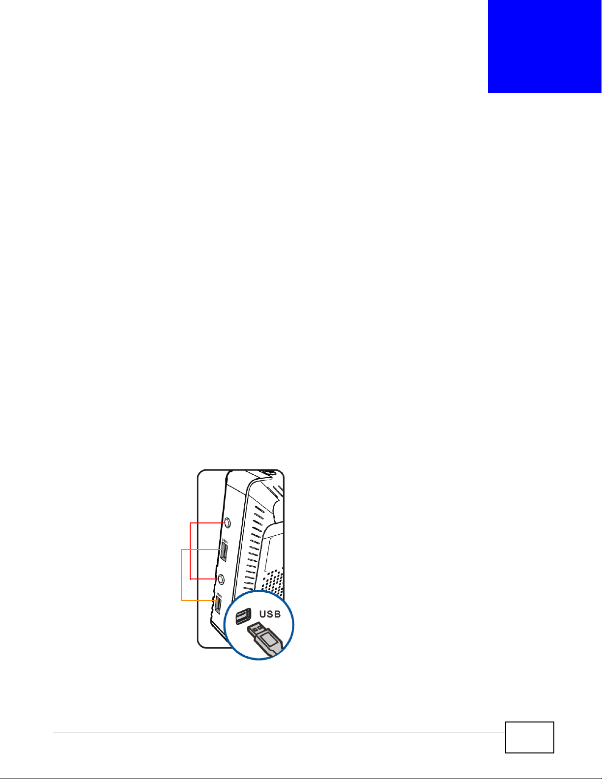
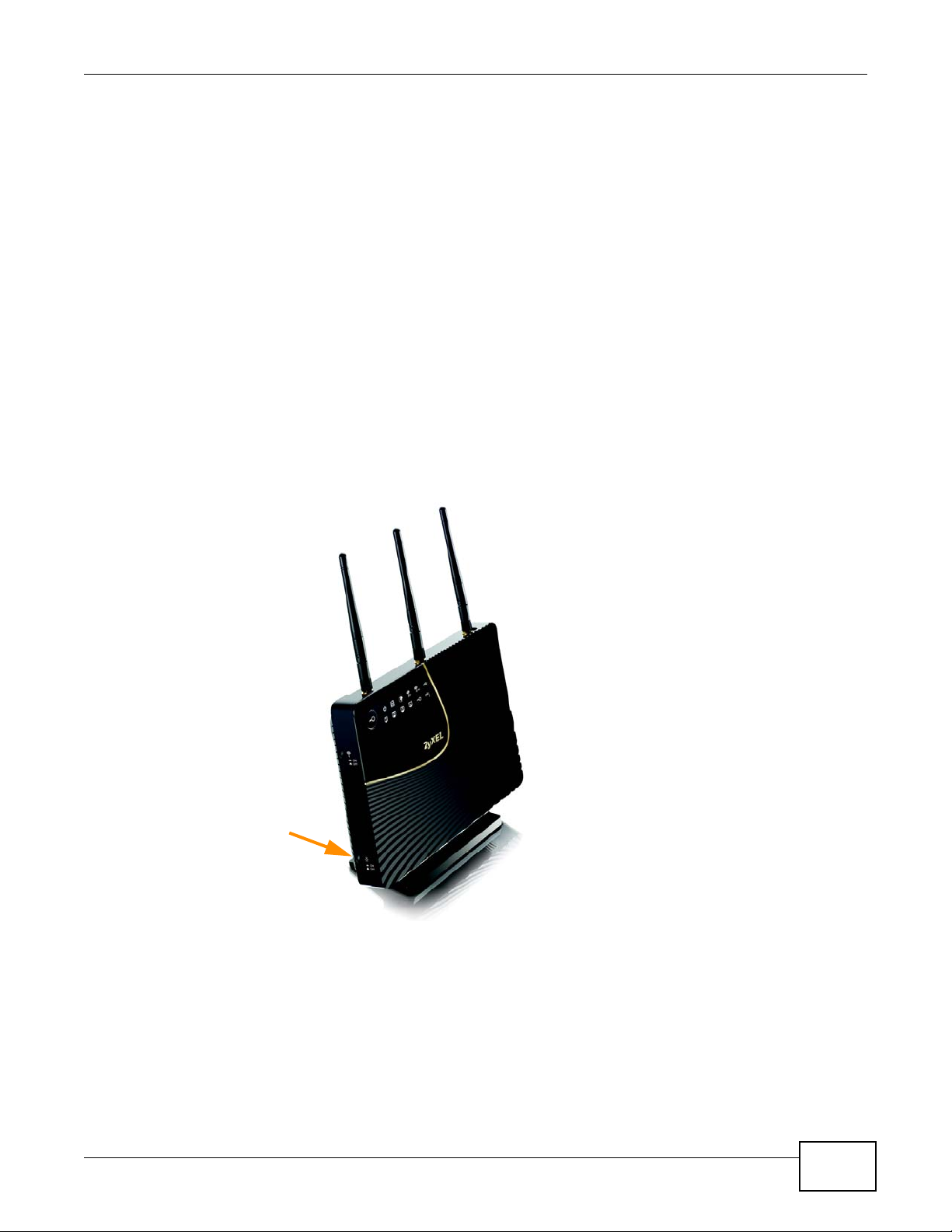
There are two USB 2.0 ports on the side panel of your NBG5715. You can connect USB (version 2.0
or lower) memory sticks, USB hard drives, or USB devices for file sharing. The NBG5715
automatically detects the USB devices.
CHAPTER 1
Introduction
T wo USB eject buttons are located above the USB ports. Push the eject button of the corresponding
USB port for 2 seconds. Make sure the USB LED is off before removing your USB device. This will
remove your USB device safely, preventing file or data loss if it is being transmitted through the
USB device.
Figure 1 USB Ports and Eject Buttons
Eject buttons
USB ports
NBG5715 User’s Guide 21

Chapter 1 Introduction
Note: For the USB function, it is strongly recommended to use version 2.0 or lower USB
storage devices (such as memory sticks, USB hard drives) and/or USB devices
(such as USB printers). Other USB products are not guaranteed to function properly
with the NBG5715.
Note: Be sure to install the ZyXEL NetUSB
functionality) from the included disc, or download the latest version from the
zyxel.com website. See Chapter 3 on page 26 for more information.
1.2 Applications
Your can create the following networks using the NBG5715:
• Wired. You can connect network devices via the Ethernet ports of the NBG5715 so that they can
communicate with each other and access the Internet.
• Wireless. Wireless clients can connect to the NBG5715 to access network resources.
• WAN. Connect to a broadband modem/router for Internet access.
• WPS. Create an instant network connection with another WPS-compatible device, sharing your
network connection with it.
• NetUSB. The NBG5715 allows you to connect a USB device (such as printer, scanner, or portable
hard disk) directly to the USB port and then share that device over the Internet. You can also
connect a USB to the NBG5715, which can then share up to 3 additional USB devices with the
rest of your personal home network.
TM
Share Center Utility (for NetUSB
1.3 Ways to Manage the NBG5715
Use any of the following methods to manage the NBG5715.
• WPS (Wi-Fi Protected Setup). You can use the WPS button or the WPS section of the Web
Configurator to set up a wireless network with your NBG5715.
• Web Configurator. This is recommended for everyday management of the NBG5715 using a
(supported) web browser.
1.4 Good Habits for Managing the NBG5715
Do the following things regularly to make the NBG5715 more secure and to manage the NBG5715
more effectively.
• Change the password. Use a password that’s not easy to guess and that consists of different
types of characters, such as numbers and letters.
• Write down the password and put it in a safe place.
22
NBG5715 User’s Guide
• Back up the configuration (and make sure you know how to restore it). Restoring an earlier
working configuration may be useful if the device becomes unstable or even crashes. If you
forget your password, you will have to reset the NBG5715 to its factory default settings. If you
backed up an earlier configuration file, you would not have to totally re-configure the NBG5715.
You could simply restore your last configuration.
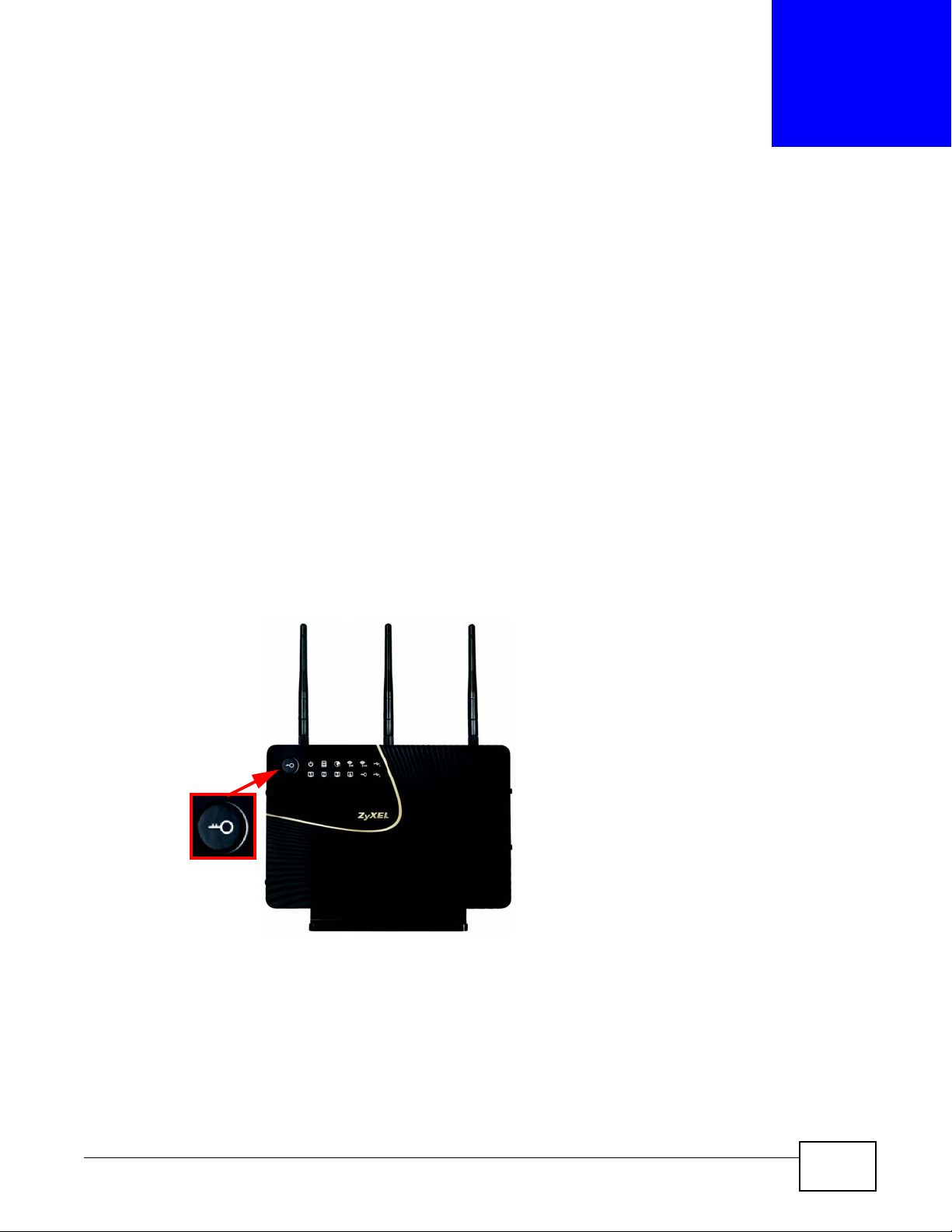
1.5 LEDs
Look at the LED lights on the front panel to determine the status of the NBG5715. Use the LED
button at the side panel of the device to turn the LED lights on or off. If you have already pushed
the LED button to the ON position but none of the LEDS are on, make sure the NBG5715 is
receiving power and the power is turned on.
Note: The Power LED will be on even if you push the LED button to the OFF position.
Figure 2 LED Button
Chapter 1 Introduction
This is for you to determine whether the NBG5715 is powered on.
LED button
NBG5715 User’s Guide
23
Chapter 1 Introduction
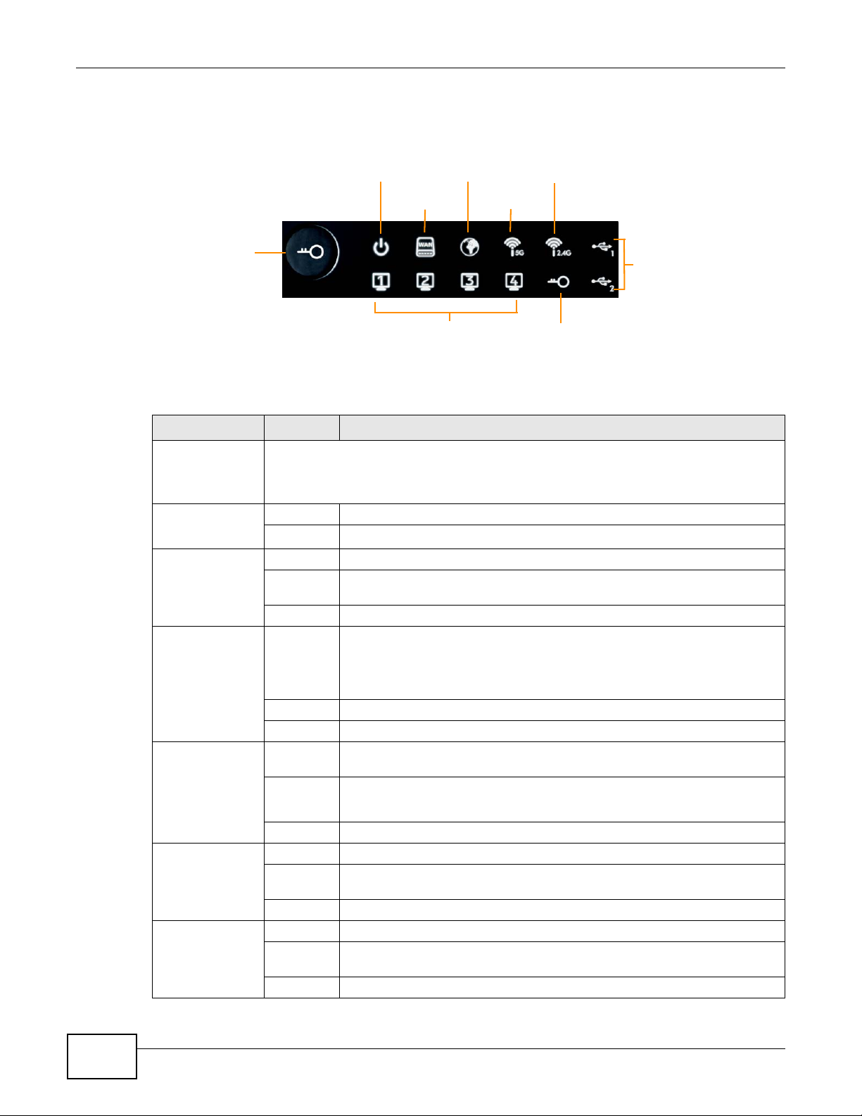
Figure 3 Front Panel
Power
WAN
Internet
WLAN 5G
WLAN 2.4G
WPS
Button
LAN 1-4
WPS
USB 1-2
The following table describes the LEDs and the WPS button.
Table 1 Front panel LEDs and WPS button
LED STATUS DESCRIPTION
WPS Button Press this button for 1 second to set up a wireless connection via WiFi Protected Setup
with another WPS-enabled client. You must press the WPS button on the client side within
120 seconds for a successful connection. See Chapter 2 on page 25 and Chapter 9 on
page 61
Power On The NBG5715 is receiving power and functioning properly.
Off The NBG5715 is not receiving power.
WAN On The NBG5715’s WAN connection is ready.
Blinking The NBG5715 is sending/receiving data through the WAN with a 1000Mbps
Off The WAN connection is not ready, or has failed.
Internet On The NBG5715 has an IP connection but no traffic.
for more information on WPS.
transmission rate.
24
Your device has a WAN IP address (either static or assigned by a DHCP
server), PPP negotiation was successfully completed (if used) and the
connection is up.
Blinking The NBG5715 is sending or receiving IP traffic.
Off The NBG5715 does not have an IP connection.
WLAN 2.4/5G On The NBG5715 is ready, but is not sending/receiving data through the 5G
wireless LAN.
Blinking The NBG5715 is sending/receiving data through the 5G wireless LAN.
The NBG5715 is negotiating a WPS connection with a wireless client.
Off The wireless LAN is not ready or has failed.
LAN 1-4 On The NBG5715’s LAN connection is ready.
Blinking The NBG5715 is sending/receiving data through the LAN with a 1000Mbps
transmission rate.
Off The LAN connection is not ready, or has failed.
USB 1-2 On The NBG5715 has a USB device installed.
Blinking The NBG5715 is transmitting and/or receiving data from routers through an
installed USB device.
Off There is no USB device connected to the NBG5715.
NBG5715 User’s Guide
2.1 Overview
Your NBG5715 supports WiFi Protected Setup (WPS), which is an easy way to set up a secure
wireless network. WPS is an industry standard specification, defined by the WiFi Alliance.
WPS allows you to quickly set up a wireless network with strong security, without having to
configure security settings manually. Each WPS connection works between two devices. Both
devices must support WPS (check each device’s documentation to make sure).
Depending on the devices you have, you can either press a button (on the device itself, or in its
configuration utility) or enter a PIN (a unique Personal Identification Number that allows one device
to authenticate the other) in each of the two devices. When WPS is activated on a device, it has two
minutes to find another device that also has WPS activated. Then, the two devices connect and set
up a secure network by themselves.
CHAPTER 2
The WPS Button
For more information on using WPS, see Chapter 9 on page 61.
Figure 4 The WPS Button
NBG5715 User’s Guide 25

ZyXEL NetUSB Share Center Utility
3.1 Overview
The ZyXEL NetUSB Share Center Utility allows you to work with the USB devices that are connected
directly to the NBG5715 as if they are connected directly to your computer. This allows you to easily
share USB-based devices such as printers, scanners, portable hard disks, MP3 players, faxes, and
digital cameras (to name a few) with all the other people in your home or office as long as they are
connected to the NBG5715 and have the ZyXEL NetUSB Share Center Utility installed.
Note: Be sure to install the ZyXEL NetUSB Share Center Utility (for NetUSB functionality)
from the included disc, or download the latest version from the zyxel.com website’ s
Download Library.
3.1.1 Quick Setup
CHAPTER 3
This section shows you how to get started using the ZyXEL NetUSB Share Center Utility.
1 Install the ZyXEL NetUSB
2 Connect a USB device to the USB port on the NBG5715.
Note: If you are connecting multiple devices to the NBG5715, first connect a USB hub to
the NBG5715 then connect your other USB devices to it.
3 Run the ZyXEL NetUSB Share Center Utility to display a list of all connected USB devices, then use
it to connect your computer to them.
Share Center Utility on each computer connected to the NBG5715.
3.1.2 Installing ZyXEL NetUSB Share Center Utility
Before you can access USB devices connected to the NBG5715, you must first install the ZyXEL
NetUSB
these devices.
Note: In order to properly use the utility with your NBG5715, ensure that the NBG5715
To install the ZyXEL NetUSB Share Center Utility:
Share Center Utility on any computer on your LAN to which you want to allow access to
firmware is version v1.00(BWQ.0) or higher. See Chapter 22 on page 166 for
information on updating your device’s firmware.
1 Insert the disc that came with your NBG5715 into your computer’s disc drive.
2 Run the Setup program by double-clicking it and then follow the on-screen instructions for
installing it on your computer.
NBG5715 User’s Guide 26
Chapter 3 ZyXEL NetUSB Share Center Utility
Note: The following operating syst ems are supported: Windows XP/Vista/7 (32 and 64-bit
versions).
3 To open the ZyXEL NetUSB Share Center Utility, double -click its system tray icon.
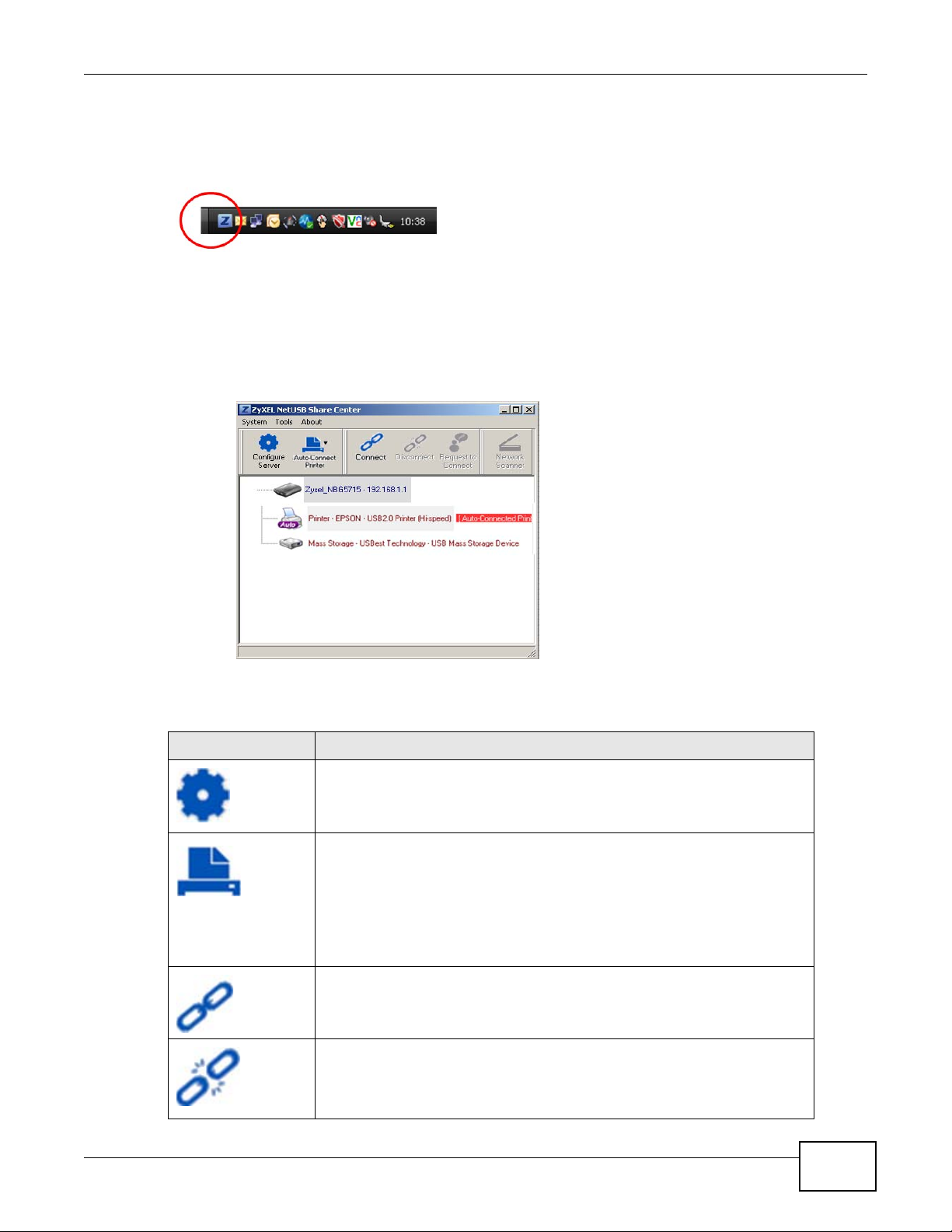
3.2 The ZyXEL NetUSB Share Center Utility
This section describes the ZyXEL NetUSB Share Center Utility main window.
Figure 5 ZyXEL NetUSB Share Center Utility Main Window
The following table describes the icons in this window.
Table 2 ZyXEL NetUSB Share Center Utility Main Window Icons
ICON DESCRIPTION
Configure Server
Click to open the NBG5715’s built-in Web Configurator, which you can use to
set up the NBG5715 (see Chapter 4 on page 33 for details).
Auto-Connect Printer
Click this if you want to automatically connect to the printer each time your
start your computer.
Note: You must first install the appropriate print driver on each computer for
which you intend to use this feature. See the documentation that came
with your printer for instructions on how to do this.
Connect
Select a USB device and then click this button to connect to it. Your computer
can connect to as many USB devices as are connected to the NBG5715.
Disconnect
Select a device to which your computer is connected and then click this
button to disconnect from it.
NBG5715 User’s Guide
27
Chapter 3 ZyXEL NetUSB Share Center Utility
Table 2 ZyXEL NetUSB Share Center Utility Main Window Icons (continued)
ICON DESCRIPTION
Request to Connect
Some USB devices may not allow automatic connections over the network. If
so, select the device in question and click this button to issue a request to
connect to it.
Network Scanner
Click this to open the scanner options on your computer for working with a
scanner connected to the network.
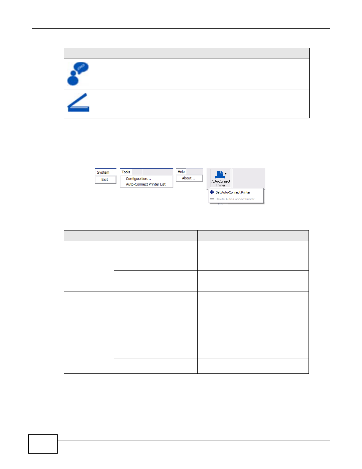
3.2.1 The Menus
This section describes the utility’s menus.
Figure 6 ZyXEL NetUSB Share Center Utility Menus
The following table describes the menus in this screen.
Table 3 ZyXEL NetUSB Share Center Utility Main Screen Menus
MENU ITEM DESCRIPTION
System Exit This closes the ZyXEL NetUSB Share Center
Tools Configuration This opens the ZyXEL NetUSB Share Center
Auto-Connect Printer List This opens the list window that displays all
Help About This opens the about window, which
Auto-Connect
Printer
Set Auto-Connect Printer This sets the selected printer to ‘auto-
Utility.
Utility configuration window.
of the printing devices connected to the
NBG5715.
provides information of the utility software
and driver versions.
connect’ , meaning your computer will always
connect to the printer over the network.
Note: You first must install the appropriate
drivers for the printer that you intend
to use.
Delete Auto-Connect Printer This removes the auto-connect option from
the selected printer.
28
NBG5715 User’s Guide
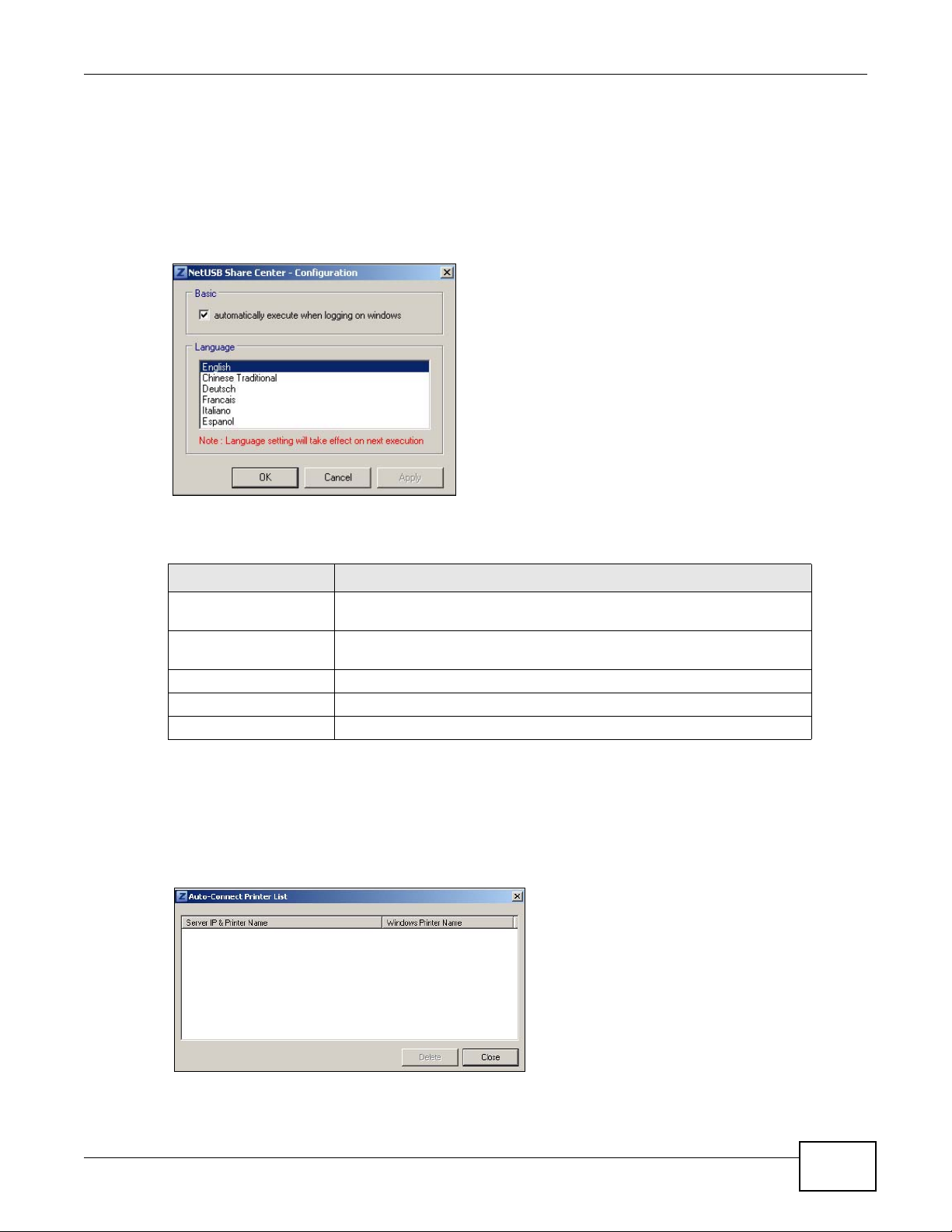
3.2.2 The Share Center Configuration Window
This section describes the utility’s configuration window, which allows y ou to set certain options for
the utility. These options do not apply to the USB devices connected to the NBG5715.
You can open it by clicking the Tools > Configuration menu command.
Figure 7 ZyXEL NetUSB Share Center Utility Configuration Window
Chapter 3 ZyXEL NetUSB Share Center Utility
The following table describes the labels in this window.
Table 4 ZyXEL NetUSB Share Center Utility Configuration Window
LABEL DESCRIPTION
Basic Select this to run the utility automatically when you log into or start up
Windows.
Language Select a language for the ZyXEL NetUSB Share Center Utility. You must
OK Click this to save your changes and close the window.
Cancel Click this cancel to close the window without saving.
Apply Click this to save your changes without closing the window.
restart the utility for the change to take effect.
3.2.3 The Auto-Connect Printer List Window
This section describes the utility’s auto-connect printer list window. You can open it by clicking the
Tools > Auto-Connect Printer List menu command.
Figure 8 ZyXEL NetUSB Share Center Utility Auto-Connect Printer List Window
NBG5715 User’s Guide
29
Chapter 3 ZyXEL NetUSB Share Center Utility
The following table describes the labels in this screen.
Table 5 ZyXEL NetUSB Share Center Utility Auto-Connect Printer List Window
LABEL DESCRIPTION
Server IP & Printer
Name
Windows Printer Name Displays a corresponding list of Windows printer names connected to this
Delete Select an printer from the list and click this to remove it.
Close Click this to close the window.
Displays a list of print server IPs and printer names connected to this
NBG5715.
devices listed in the other list.
3.3 Manually Connecting to USB Devices
This example shows you how to connect to a USB device over your NBG5715 network. Makes sure
that you have first installed the ZyXEL NetUSB Share Center Utility on the computer to which you
want to connect the USB devices.
Note: If you do this with a USB printer but do not yet have the print driver installed you
will be prompted to install one by the Windows New Hardware Wizard.
1 Connect a USB device to the NBG5715.
2 In the ZyXEL NetUSB Share Center Utility, select the device and click Connect.
30
NBG5715 User’s Guide

Chapter 3 ZyXEL NetUSB Share Center Utility
3 The device mounts on your system.
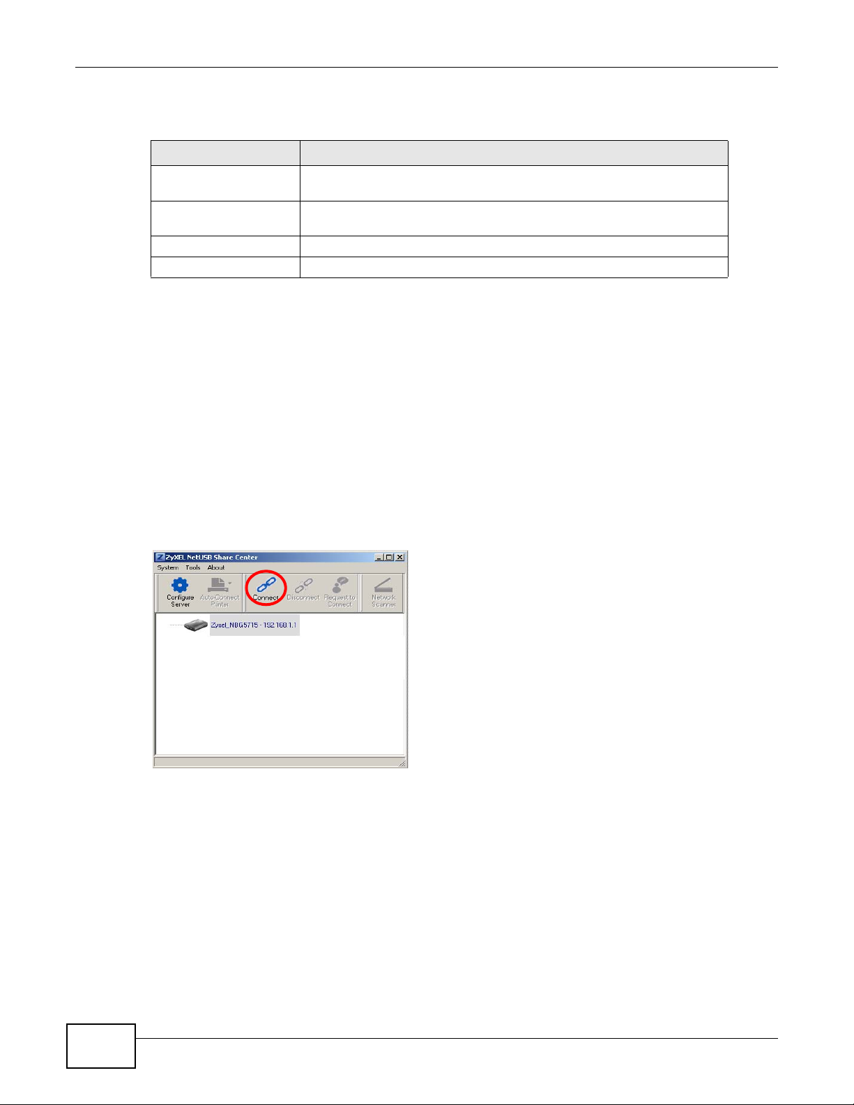
3.4 Automatically Connecting to a USB Printer
This example shows you how to set your computer to automatically connect to a shared USB printer
over your NBG5715 network each time you log into your computer. Makes sure that you have first
installed the ZyXEL NetUSB Share Center Utility.
1 Connect a USB printer to the NBG5715.
2 Open the ZyXEL NetUSB Sharing Center Utility on the computer that you want to use to connect
to the printer.
Click the Connect button. You may be prompted to install a printer driver or to configure other
settings.
3 Finally, click the Auto-Connect Printer menu and select Set Auto-Connect Printer from the
menu.
NBG5715 User’s Guide
31

Chapter 3 ZyXEL NetUSB Share Center Utility
32
NBG5715 User’s Guide

4.1 Overview
This chapter describes how to access the NBG5715 Web Configurator and provides an overview of
its screens.
The Web Configurator is an HTML-based management interface that allows easy setup and
management of the NBG5715 via Internet browser. Use Internet Explorer 6.0 and later versions,
Mozilla Firefox 3 and later versions, or Safari 2.0 and later versions. The recommended screen
resolution is 1024 by 768 pixels.
In order to use the Web Configurator you need to allow:
• Web browser pop-up windows from your device. Web pop-up blocking is enabled by default in
Windows XP SP (Service Pack) 2.
• JavaScript (enabled by default).
• Java permissions (enabled by default).
CHAPTER 4
Introducing the Web Configurator
Refer to the Troubleshooting chapter (Chapter 23 on page 171) to see how to make sure these
functions are allowed in Internet Explorer.
4.2 Accessing the Web Configurator
1 Make sure your NBG5715 hardware is properly connected and prepare your computer or computer
network to connect to the NBG5715 (refer to the Quick Start Guide).
2 Launch your web browser.
3 Type "http://192.168.1.1" as the website address.
Your computer must be in the same subnet in order to access this website address.
4.2.1 Login Screen
Note: If this is the first time you are acc essing the Web Configurator, you may be
redirected to the Wizard. Refer to Chapter 4 on page 33 for the Connection Wizard
screens.
NBG5715 User’s Guide 33

Chapter 4 Introducing the Web Configurator
The Web Configurator initially displays the following login screen.
Figure 9 Login screen
The following table describes the labels in this screen.
Table 6 Login screen
LABEL DESCRIPTION
Language Select the language you want to use to configure the Web Configurator. Click
Password Type "1234" (default) as the password.
4.2.2 Weather Edit
You can change the temperature unit and select the location for which you want to know the
weather.
Click the icon to change the Weather display.
Figure 10 Change Weather
Login.
This shows the current weather, either in celsius or fahrenheit, of the city you
specify in Section 4.2.2 on page 34.
This shows the time (hh:mm:ss) and date (yyyy:mm:dd) of the timezone you
select in Section 4.2.3 on page 35 or Section 22.5 on page 165. The time is in
24-hour format, for example 15:00 is 3:00 PM.
34
NBG5715 User’s Guide

The following table describes the labels in this screen.
Table 7 Change Weather
LABEL DESCRIPTION
o
C or oF Choose which temperature unit you want the NBG5715 to display.
Change Location Select the location for which you want to know the weather. If the city you want
Finish Click this to apply the settings and refresh the date and time display.
4.2.3 Time/Date Edit
One timezone can cover more than one country. You can choose a particular country in which the
NBG5715 is located and have the NBG5715 display and use the current time and date for its logs.
Click the icon to change the Weather display.
Figure 11 Change Password Screen
Chapter 4 Introducing the Web Configurator
is not listed, choose one that is closest to it.
The following table describes the labels in this screen.
Table 8 Change Password Screen
LABEL DESCRIPTION
Change time zone Select the specific country whose current time and date you want the NBG5715
to display.
Finish Click this to apply the settings and refresh the weather display.
Note: You can also edit the timezone in Section 22.5 on page 165.
4.3 Resetting the NBG5715
If you forget your password or IP address, or you cannot access the W eb Configurator, you will need
to use the RESET button at the back of the NBG5715 to reload the factory-default configuration
file. This means that you will lose all configurations that you had previously saved, the password
will be reset to “1234” and the IP address will be reset to “192.168.1.1”.
4.3.1 How to Use the RESET Button
1 Make sure the power LED is on.
2 Press the RESET button for longer than 1 second to restart/reboot the NBG5715.
3 Press the RESET button for longer than 5 seconds to set the NBG5715 back to its factory-default
configurations.
NBG5715 User’s Guide
35

Chapter 4 Introducing the Web Configurator
36
NBG5715 User’s Guide

5.1 Overview
This chapter discusses read-only information related to the device state of the NBG5715.
To access the Monitor screens, go to Expert Mode after login, then click .
CHAPTER 5
Monitor and Summary
You can also click the Details links in the Summary table of the Status screen to view the
bandwidth consumed, packets sent/received as well as the status of clients connected to the
NBG5715.
5.2 What You Can Do in this Chapter
•Use the Log screens to see the logs for the activity on the NBG5715 (Section 5.3 on page 38).
•Use the DHCP Table screen to view information related to your DHCP status (Section 5.4 on
page 38).
•use the Packet Statistics screen to view port status, packet specific statistics, the "system up
time" and so on (Section 5.5 on page 40).
•Use the VPN Monitor screen to view the active VPN connections (Section 5.6 on page 41).
•Use the WLAN_2.4G/5G Station Status screen to view the 2.4G wireless stations that are
currently associated to the NBG5715 (Section 5.7 on page 41).
NBG5715 User’s Guide 37

Chapter 5 Monitor and Summary
5.3 The Log Screen
The Web Configurator allows you to look at all of the NBG5715’s logs in one location.
5.3.1 View Log
Use the View Log screen to see the logged messages for the NBG5715. The log wraps around and
deletes the old entries after it fills. Select what logs you want to see from the Display drop list. The
log choices depend on your settings in the Log Settings screen. Click Refresh to renew the log
screen. Click Clear to delete all the logs.
Figure 12 View Log
You can configure which logs to display in the View Log screen. Go to the Log Settings screen
and select the logs you wish to display . Click Apply to sa ve your settings. Click Refresh to start the
screen afresh.
Figure 13 Log Settings
5.4 DHCP Table
DHCP (Dynamic Host Configuration Protocol, RFC 2131 and RFC 2132) allows individual clients to
obtain TCP/IP configuration at start-up from a server. You can configure the NBG5715’s LAN as a
DHCP server or disable it. When configured as a server, the NBG5715 provides the TCP/IP
configuration for the clients. If DHCP service is disabled, you must have another DHCP server on
that network, or else the computer must be manually configured.
38
Click Monitor > DHCP Table or the DHCP Table (Details...) hyperlink in the Status screen.
Read-only information here relates to your DHCP status. The DHCP table shows current DHCP client
NBG5715 User’s Guide

Chapter 5 Monitor and Summary
information (including MAC Address, IP Address, and Expiration time) of all network clients
using the NBG5715’s DHCP server.
Figure 14 Summary: DHCP Table
The following table describes the labels in this screen.
Table 9 Summary: DHCP Table
LABEL DESCRIPTION
# This is the index num ber of the host computer.
Status This field displays whether the connection to the host computer is up (a yellow bulb)
Host Name This field displays the computer host name.
IP Address This field displays the IP address relative to the # field listed above.
MAC Address This field shows the MAC address of the computer with the name in the Host Name
Reserve Select this if you want to reserve the IP address for this specific MAC address.
Apply Click Apply to save your changes back to the NBG5715.
Reset Click Cancel to reload the previous configuration for this screen.
or down (a gray bulb).
field.
Every Ethernet device has a unique MAC (Media Access Control) address which
uniquely identifies a device. The MAC address is assigned at the factory and consists
of six pairs of hexadecimal characters, for example, 00:A0:C5:00:00:02.
NBG5715 User’s Guide
39

Chapter 5 Monitor and Summary
5.5 Packet Statistics
Click Monitor > Packet Statistics or the Packet Statistics (Details...) hyperlink in the Status
screen. Read-only information here includes port status, packet specific statistics and the "system
up time". The Poll Interval(s) field is configurable and is used for refreshing the screen.
Figure 15 Summary: Packet Statistics
The following table describes the labels in this screen.
Table 10 Summary: Packet Statistics
LABEL DESCRIPTION
Port This is the NBG5715’s port type.
Status For the LAN ports, this displays the port speed and duplex setting or Down
when the line is disconnected.
For the WAN port, it displays the port speed and duplex setting if you’re using
Ethernet encapsulation and Idle (line (ppp) idle), Dial (starting to trigger a
call) and Drop (dropping a call) if you're using PPPoE or PPTP encapsulation.
This field displays Down when the line is disconnected.
For the WLAN, it displays the maximum transmission rate when the WLAN is
enabled and Down when the WLAN is disabled.
TxPkts This is the number of transmitted packets on this port.
RxPkts This is the number of received packets on this port.
Collisions This is the number of collisions on this port.
Tx B/s This displays the transmission speed in bytes per second on this port.
Rx B/s This displays the reception speed in bytes per second on this port.
Up Time This is the total time the NBG5715 has been for each session.
System Up Time This is the total time the NBG5715 has been on.
Poll Interval(s) Enter the time interval in seconds for refreshing statistics in this field.
Set Interval Click this button to apply the new poll interval you entered in the Poll
Interval(s) field.
Stop Click Stop to stop refreshing statistics.
40
NBG5715 User’s Guide

5.6 VPN Monitor
Click Monitor > VPN Monitor or the VPN Monitor (Details...) hyperlink in the Status screen.
This screen displays read-only information about the active VPN connections. Click the Refresh
button to update the screen. A Security Association (SA) is the group of security settings related to
a specific VPN tunnel.
Figure 16 Summary: Security Associations
The following table describes the labels in this screen.
Table 11 Summary: Security Associations
LABEL DESCRIPTION
Status This field displays whether the VPN connection is up (a yellow bulb) or
Connection Name This field displays the identification name for this VPN policy.
Remote Gateway This is the static WAN IP address or URL of the remote IPSec router.
Local Address This is the IP address of computer(s) on your local network behind your
Remote Address This is the IP address of computer(s) on the remote network behind the
Refresh Click this button to update the screen’s statistics immediately.
Chapter 5 Monitor and Summary
down (a gray bulb).
NBG5715.
remote IPSec router.
5.7 WLAN_2.4G/5G Station Status
Click Monitor > WLAN_2.4G/5G Station Status or the WLAN 2.4G/5G WLAN Station Status
(Details...) hyperlink in the Status screen. View the wireless stations that are currently associated
to the NBG5715 in the Association List. Association means that a wireless client (for example,
your network or computer with a wireless network card) has connected successfully to the AP (or
wireless router) using the same SSID, channel and security settings.
Figure 17 Summary: Wireless Association List
NBG5715 User’s Guide
41

Chapter 5 Monitor and Summary
The following table describes the labels in this screen.
Table 12 Summary: Wireless Association List
LABEL DESCRIPTION
# This is the index number of an associated wireless station.
MAC Address This field displays the MAC address of an associated wireless station.
Association Time This field displays the time a wireless station first associated with the
NBG5715’s WLAN network.
42
NBG5715 User’s Guide

6.1 Overview
This chapter introduces the different modes available on your NBG5715. First, the term “mode”
refers to two things in this User’s Guide.
• Web Configurator mode. This refers to the Web Configurator interface you want to use for
editing NBG5715 features.
• Router mode: This is the device mode of the NBG5715. Use this mode to connect the local
network to another network, like the Internet. Go to Section 8.2 on page 56 to view the Status
screen in this mode.
6.1.1 Web Configurator Modes
This refers to the configuration interface of the Web Configurator, which has two modes:
CHAPTER 6
NBG5715 Modes
• Easy: The W eb Configurator shows this mode by default. R efer to Chapter 7 on page 44 for more
information on the screens in this mode. This interface may be sufficient for users who just want
to use the device.
• Expert: Advanced users can change to this mode to customize all the functions of the NBG5715.
Click Expert Mode after logging into the Web Configurator. The User’s Guide Chapter 4 on page
33 discusses the screens in this mode.
NBG5715 User’s Guide 43

7.1 Overview
The Web Configurator is set to Easy Mode by default. You can configure several key features of the
NBG5715 in this mode. This mode is useful to users who are not fully familiar with some features
that are usually intended for network administrators.
When you log in to the Web Configurator, the following screen opens.
Figure 18 Easy Mode: Network Map
CHAPTER 7
Easy Mode
Navigation Panel
Network Map
Control Panel
Go to
Status
Screen
NBG5715 User’s Guide 44

Click Status to open the following screen.
Figure 19 Easy Mode: Status Scree n
Navigation Panel
Go to
Network
Map
Screen
Status Screen
Control Panel
Chapter 7 Easy Mode
7.2 What You Can Do in this Chapter
You can do the following in this mode:
•Use this Navigation Panel to opt out of the Easy mode (Section 7.3 on page 45).
•Use the Network Map screen to check if your NBG5715 can ping the gateway and whether it is
connected to the Internet (Section 7.4 on page 46).
•Use the Control Panel to configure and enable NBG5715 features, including wireless security,
wireless scheduling and bandwidth management and so on (Section 7.5 on page 47).
•Use the Status Screen to view read-only information about the NBG5715, including the WAN IP,
MAC Address of the NBG5715 and the firmware version (Section 7.6 on page 53).
7.3 Navigation Panel
Use this navigation panel to opt out of the Easy mode.
Figure 20 Control Panel
NBG5715 User’s Guide
45

Chapter 7 Easy Mode
The following table describes the labels in this screen.
Table 13 Control Panel
ITEM DESCRIPTION
Home Click this to go to the Login page.
Expert Mode Click this to change to Expert mode and customize features of the
Logout Click this to end the Web Configurator session.
7.4 Network Map
Note: The Network MAP is viewable by Windows XP (need to install patch), Windows
Vista and Windows 7 users only. For Windows XP (Service Pack 2) users, you can
see the network devices connected to the NBG5715 by downloading the LLTD (Link
Layer Topology Discovery) patch from the Microsoft Website.
Note: Don’t worry if the Network Map does not display in your web browser. This feature
may not be supported by your system. You can still configure the Control Panel
(Section 7.5 on page 47) in the Easy Mode and the NBG5715 features that you
want to use in the Expert Mode.
NBG5715.
When you log into the Network Configurator, the Network Map is shown as follows.
Figure 21 Network Map
The line connecting the NBG5715 to the gateway becomes green when the NBG5715 is able to ping
the gateway. It become s red when the ping initiating from the NBG5715 does not get a response
from the gateway. The same rule applies to the line connecting the gateway to the Internet.
You can also view the devices (represented by icons indicating the kind of network device)
connected to the NBG5715, including those connecting wirelessly. Right-click on the NBG5715 icon
to refresh the network map and go to the Wizard. Right click on the other icons to view information
about the device.
46
NBG5715 User’s Guide

7.5 Control Panel
The features configurable in Easy Mode are shown in the Control Panel.
Figure 22 Control Panel
Switch ON to enable the feature. Otherwise, switch OFF. If the feature is turned on, the green light
flashes. If it is turned off, the red light flashes.
Additionally, click the feature to open a screen where you can edit its settings.
The following table describes the labels in this screen.
Table 14 Control Panel
ITEM DESCRIPTION
Game Engine Switch ON to maximize bandwidth for gaming traffic in your network.
Power Saving Click this to schedule the wireless feature of the NBG5715.
Chapter 7 Easy Mode
Otherwise, switch OFF.
Refer to Section 7.5.1 on page 48 to see this screen.
Disabling the wireless function helps lower the energy consumption of the
NBG5715.
Switch ON to apply wireless scheduling. Otherwise, switch OFF.
Refer to Section 7.5.2 on page 48 to see this screen.
Content Filter Click this to restrict access to certain websites, based on keywords
Bandwidth MGMT Click this to edit bandwidth management for predefined applications.
Firewall Switch ON to ensure that your network is protected from Denial of Service
Wireless Security Click this to configure the wireless security, such as SSID, security mode
contained in URLs, to which you do not want users in your network to
open.
Switch ON to apply website filtering. Otherwise , switch OFF.
Refer to Section 7.5.3 on page 49 to see this screen.
Switch ON to have the NBG5715 management bandwidth for uplink and
downlink traffic according to an application or service. Otherwise, switch
OFF.
Refer to Section 7.5.4 on page 50 to see this screen.
(DoS) attacks. Otherwise, switch OFF.
Refer to Section 7.5.5 on page 51 to see this screen.
and WPS key on your NBG5715.
Refer to Section 7.5.6 on page 51 to see this screen.
NBG5715 User’s Guide
47

Chapter 7 Easy Mode
7.5.1 Game Engine
When this feature is enabled, the NBG5715 maximizes the bandwidth for gaming traffic that
it forwards out through an interface.
Figure 23 Game Engine
Note: When this is switched on, the Game Console tab in the Bandwid th Mgmt screen is
automatically positioned on top.
Turn this off if your network is not using gaming.
Click OK to close this screen.
7.5.2 Power Saving
Use this screen to set the day of the week and time of the day when your wireless LAN is turned on
and off. Wireless LAN scheduling is disabled by default.
Disabling the wireless capability lowers the energy consumption of the of the NBG5715.
Figure 24 Power Saving
48
NBG5715 User’s Guide

Chapter 7 Easy Mode
The following table describes the labels in this screen.
Table 15 Power Saving
LABEL DESCRIPTION
Wireless Radio Choose whether you want to apply the power saving schedule to 2.4G hz or 5G
WLAN Status Select On or Off to specify whether the Wireless LAN is turned on or off
Day Select Everyday or the specific days to turn the Wireless LAN on or off.
Except for the
following times
(24-Hour Format)
Apply Click Apply to save your changes back to the NBG5715.
Reset Click Reset to begin configuring this screen afresh.
hz wireless radio.
(depending on what you selected in the WLAN Status field). This field works in
conjunction with the Day and For the following times fields.
If you select Everyday you can not select any specific days. This field works in
conjunction with the For the following times field.
Select a begin time using the first set of hour and minute (min) drop down
boxes and select an end time using the second set of hour and minute (min)
drop down boxes. If you have chosen On earlier for the WLAN Status the
Wireless LAN will turn on between the two times you enter in these fields. If you
have chosen Off earlier for the WLAN Status the Wireless LAN will turn off
between the two times you enter in these fields.
In this time format, midnight is 00:00 and progres ses up to 24:00. Fo r example,
6:00 PM is 18:00.
7.5.3 Content Filter
Use this screen to restrict access to certain websites, based on keywords contained in URLs, to
which you do not want users in your network to open.
Figure 25 Content Filter
NBG5715 User’s Guide
49

Chapter 7 Easy Mode
The following table describes the labels in this screen.
Table 16 Content Filter
LABEL DESCRIPTION
Add Click Add after you have typed a keyword.
Repeat this procedure to add other keywords. Up to 64 keywords are allowed.
Note: The NBG5715 does not recognize wildcard characters as keywords.
When you try to access a web page containing a keyword, you will get a
message telling you that the content filter is blocking this request.
Delete Highlight a keyword in the text box and click Delete to remove it. The keyword
disappears from the text box after you click Apply.
Apply Click Apply to save your changes.
Cancel Click Cancel to close this screen without saving any changes.
7.5.4 Bandwidth MGMT
Use this screen to set bandwidth allocation to pre-defined services and applications for bandwidth
allocation.
The NBG5715 uses bandwidth management for incoming and outgoing traffic. Rank the services
and applications by dragging them accordingly from High to Low and click Apply. Click Cancel to
close the screen.
Figure 26 Bandwidth MGNT
Use your mouse
to drag the items
according to how
you want to
prioritize them.
Left-click and
slide up or down.
50
NBG5715 User’s Guide

7.5.5 Firewall
Enable this feature to protect the network from Denial of Service (DoS) attacks. The NBG5715
blocks repetitive pings from the WAN that can otherwise cause systems to slow down or hang.
Figure 27 Firewall
Click OK to close this screen.
7.5.6 Wireless Security
Use this screen to configure security for your the Wireless LAN. You can enter the SSID and select
the wireless security mode in the following screen.
Note: You can enable the Wireless function of your NBG5715 by first turning on the
switch in the side panel.
Chapter 7 Easy Mode
Figure 28 Wireless Security
The following table describes the general wireless LAN labels in this screen.
Table 17 Wireless Security
LABEL DESCRIPTION
Wireless Radio Choose whether you want to apply the wireless security to 2.4G hz or 5G hz
wireless radio.
Wireless
Network Name
(SSID)
(Service Set IDentity) The SSID identifies the Service Set with which a wireless
station is associated. Wireless stations associating to the access point (AP) must
have the same SSID. Enter a descriptive name (up to 32 keyboard characters) for
the wireless LAN.
NBG5715 User’s Guide
51

Chapter 7 Easy Mode
Table 17 Wireless Security (continued)
LABEL DESCRIPTION
Security mode Select WPA-PSK or WPA2-PSK to add security on this wireless network. The
Wireless
password
Verify
password
Apply Click Apply to save your changes back to the NBG5715.
Cancel Click Cancel to close this screen.
WPS Click this to configure the WPS screen.
wireless clients which want to associate to this network must have same wireless
security settings as this devic e. After you select to use a securit y , additional options
appears in this screen.
Select No Security to allow any client to connect to this network without
authentication.
This field appears when you choose wither WPA-PSK or WPA2-PSK as the
security mode.
Type a pre-shared key from 8 to 63 case-sensitive keyboard characters.
Type the password again to confirm.
You can transfer the wireless settings configured here (Wireless Security screen)
to another wireless device that supports WPS.
7.5.7 WPS
Use this screen to add a wireless station to the network using WPS. Click WPS in the Wireless
Security to open the following screen.
Figure 29 Wireless Security: WPS
52
NBG5715 User’s Guide

Chapter 7 Easy Mode
The following table describes the labels in this screen.
Table 18 Wireless Security: WPS
LABEL DESCRIPTION
Wireless Security Click this to go back to the Wireless Security screen.
WPS Create a secure wireless network simply by pressing a button.
The NBG5715 scans for a WPS-enabled device within the range and performs
wireless security information synchronization.
Note: After you click the WPS button on this screen, you have to press a similar
button in the wireless station utility within 2 minutes. To add the second
wireless station, you have to press these buttons on both device and the
wireless station again after the first 2 minutes.
Register Create a secure wireless network simply by entering a wireless client's PIN
(Personal Identification Number) in the NBG5715’s interface and pushing this
button.
Type the same PIN number generated in the wireless station’s utility. Then click
Register to associate to each other and perform the wireless security
information synchronization.
Exit Click Exit to close this screen.
7.6 Status Screen in Easy Mode
In the Network Map screen, click Status to view read-only information about the NBG5715.
Figure 30 Status Screen in Easy Mode
The following table describes the labels in this screen.
Table 19 Status Screen in Easy Mode
ITEM DESCRIPTION
Name This is the name of the NBG5715 in the network. You can change this in
the Maintenance > General screen in Section 22.3 on page 163.
Time This is the current system date and time.
The date is in YYYY:MM:DD (Year-Month-Day) format. The time is in
HH:MM:SS (Hour:Minutes:Seconds) format.
WAN IP This is the IP address of the WAN port.
MAC Address This is the MAC address of the NBG5715.
NBG5715 User’s Guide
53

Chapter 7 Easy Mode
Table 19 Status Screen in Easy Mode (continued)
ITEM DESCRIPTION
Firmware Version This shows the firmware version of the NBG5715.
Wireless_2.4G/5G
Network Name (SSID)
Security This shows the wireless security used by the NBG5715.
The firmware version format shows the trunk version, model code and
release number.
This shows the SSID of the wireless network. You can configure this in the
Wireless Security screen (Section 7.5.6 on page 51 ; Section 11.2 on page
82).
54
NBG5715 User’s Guide

8.1 Overview
The NBG5715 operates as a router. Routers are used to connect the local network to another
network (for example, the Internet). In the figure below, the NBG5715 connects the local network
(LAN1 ~ LAN4) to the Internet.
Figure 31 NBG5715 Network
CHAPTER 8
Router Mode
Modem
Note: The Status screen is shown after changing to the Expert mode of the Web
Configurator. It varies depending on the device mode of your NBG5715.
NBG5715 User’s Guide 55

Chapter 8 Router Mode
8.2 Router Mode Status Screen
Click to open the status screen.
Figure 32 Status: Router Mode
The following table describes the icons shown in the Status screen.
Table 20 Status: Router Mode
ICON DESCRIPTION
Click this icon to logout of the web configurator.
Click this icon to view copyright and a link for related product information.
Click this icon to go to Easy Mode. See Chapter 7 on page 44.
Select a number of seconds or None from the drop-down list box to refresh all screen
statistics automatically at the end of every time interval or to not refresh the screen
statistics.
Click this button to refresh the status screen statistics.
Click this icon to see the Status page. The information in this screen depends on the
device mode you select.
Click this icon to see the Monitor navigation menu.
56
NBG5715 User’s Guide

Chapter 8 Router Mode
Table 20 Status: Router Mode (continued)
ICON DESCRIPTION
Click this icon to see the Configuration navigation menu.
Click this icon to see the Maintenance navigation menu.
The following table describes the labels shown in the Status screen.
Table 21 Status Screen: Router Mode
LABEL DESCRIPTION
Device Information
Host Name This is the System Name you enter in the Maintenance > General screen. It is
for identification purposes.
Model Number This is the model name of your device.
MAC Address This shows the WAN Ethernet adapter MAC Address of your device.
Firmware Version This is the firmware version and the date created.
WAN Information
- IP Address This shows the WAN port’s IP address.
- IP Subnet Mask This shows the WAN port’s subnet mask.
- Default Gateway This shows the WAN port’s gateway IP address.
LAN Information
- IP Address This shows the LAN port’s IP address.
- IP Subnet Mask This shows the LAN port’s subnet mask.
- DHCP This shows the LAN port’s DHCP role - Server or Disable.
WLAN_2.4G Information
- SSID This shows a descriptive name used to identify the NBG5715 in the wireless LAN.
- Channel This shows the channel number which the NBG5715 is currently using over the
- Security This shows the level of wireless security the NBG5715 is using.
WLAN_5G Information
- SSID This shows a descriptive name used to identify the NBG5715 in the wireless LAN.
- Channel This shows the channel number which the NBG5715 is currently using over the
- Security This shows the level of wireless security the NBG5715 is using.
- Firewall This shows whether the firewall is enabled or not.
System Status
Item This column shows the type of data the NBG5715 is recording.
Data This column shows the actual data recorded by the NBG5715.
System Up Time This is the total time the NBG5715 has been on.
Current Date/Time This field displays your NBG5715’s present date and time.
System Resource
- CPU Usage This displays what percentage of the NBG5715’s processing ability is currently
wireless LAN.
wireless LAN.
used. When this percentage is close to 100%, the NBG5715 is running at full load,
and the throughput is not going to improve anymore. If you want some applications
to have more throughput, you should turn off other applications (for example,
using bandwidth management.)
NBG5715 User’s Guide
57

Chapter 8 Router Mode
Table 21 Status Screen: Router Mode (continued)
LABEL DESCRIPTION
- Memory Usage This shows what percentage of the heap memory the NBG5715 is using.
Interface Status
Interface This displays the NBG5715 port types. The port types are: WAN, LAN and WLAN.
Status For the LAN and WAN ports, this fiel d displays Down (line is down) or Up (line is up
or connected).
For the WLAN, it displays Up when the WLAN is enabled or Down when the WLAN
is disabled.
Rate For the LAN ports, this displays the port speed and duplex setting or N/A when the
line is disconnected.
For the WAN port, it displays the port speed and duplex setting if you’re using
Ethernet encapsulation. This field displays N/A when the line is disconnected.
For the WLAN 2.4G/5G, it displays the maximum transmission rate when the WLAN
2.4G/5G is enabled and N/A when the WLAN is disabled.
Summary
Packet Statistics Click Details... to go to the Monitor > Packet Statistics screen (Section 5.5 on
WLAN_2.4G Station
Status
WLAN_5G Station Status Click Details... to go to the Monitor > WLAN_5G Station Status screen (Section
IPSec VPN Status Click Details... to go to the Monitor > VPN Monitor screen (Section 5.4 on page
page 40). Use this screen to view port status an d p acket specific statistics.
Click Details... to go to the Monitor > WLAN_2.4G Station Status screen
(Section 5.7 on page 41). Use this screen to view the wireless stations that are
currently associated to the NBG5715.
5.7 on page 41). Use this screen to view the wireless stations that are currently
associated to the NBG5715.
38). Use this screen to view the active VPN connections.
8.2.1 Navigation Panel
Use the sub-menus on the navigation panel to configure NBG5715 features.
Figure 33 Navigation Panel: Router Mode
58
NBG5715 User’s Guide

Chapter 8 Router Mode
The following table describes the sub-menus.
Table 22 Navigation Panel: Router Mode
LINK TAB FUNCTION
Status This screen shows the NBG5715’s general device, system and
MONITOR
Log Use this screen to view the list of activities recorded by your
DHCP Table Use this screen to view current DHCP client information.
Packet Statistics Use this screen to view port status and packet specific statistics.
VPN Monitor Use this screen to view the active VPN connections.
WLAN_2.4G
Station Status
WLAN_5G
Station Status
CONFIGURATION
Network
WAN Broadband This screen allows you to configure ISP parameters, WAN IP
Advanced Use this screen to configure other advanced properties.
Wireless LAN
2.4G
Wireless LAN 5GGeneral Use this screen to enable the 5G wireless LAN network, configure
LAN IP Use this screen to configure LAN IP address and subnet mask.
General Use this screen to enable the 2.4G wireless LAN network,
MAC Filter Use the MAC filter screen to configure the NBG5715 to block
Advanced This screen allows you to configure advanced wireless settings.
QoS Use this screen to configure Wi-Fi Multimedia Quality of Service
WPS Use this screen to configure WPS.
WPS Station Use this screen to add a wireless station using WPS.
Scheduling Use this screen to sche dule the times the Wireless LAN is enabled.
IP Alias Use this screen to have the NBG5715 apply IP alias to create LAN
interface status information. Use this screen to access the wizard,
and summary statistics tables.
NBG5715.
Use this screen to view the 2.4G wireless stations that are
currently associated to the NBG5715.
Use this screen to view the 5G wireless stations that are currently
associated to the NBG5715.
address assignment, DNS servers and the WAN MAC address.
configure its SSID, channel, and the wireless security level.
access to devices or block the devices from accessing the
NBG5715.
(WMM QoS). WMM QoS allows you to prioritize wireless traffic
according to the delivery requirements of individual services.
its SSID, channel, and the wireless security level.
access to devices or block the devices from accessing the
NBG5715.
(WMM QoS). WMM QoS allows you to prioritize wireless traffic
according to the delivery requirements of individual services.
subnets.
NBG5715 User’s Guide
59

Chapter 8 Router Mode
Table 22 Navigation Panel: Router Mode (continued)
LINK TAB FUNCTION
DHCP Server General Use this screen to enable the NBG5715’s DHCP server.
NAT General Use this screen to enable NAT.
Dynamic
DNS
Static Route Static Route Use this screen to configure IP static routes.
Security
Firewall General Use this screen to activate/deactivate the firewall.
IPSec VPN General Use this screen to display and manage the NBG5715’s VPN rules
Management
Bandwidth
MGMT
Remote
MGMT
UPnP UPnP Use this screen to enable UPnP on the NBG5715.
MAINTENANCE
General General Use this screen to view and change administrative settings such
Password Password
Time Time Setting Use this screen to change your NBG5715’s time and date.
Firmware
Upgrade
Backup/
Restore
Language Language This screen allows you to select the language you prefer.
Advanced Use this screen to assign IP addresses to specific individual
computers based on their MAC addresses and to have DNS
servers assigned by the DHCP server.
Client List Use this screen to view information related to your DHCP status.
Port
Forwaring
NAT
Advanced
Dynamic DNS Use this screen to set up dynamic DNS.
Services This screen shows a summary of the firewall rules, and allows you
SA Monitor Use this screen to display and manage active VPN connections.
General Use this screen to enable bandwidth management.
Advance Use this screen to set the upstream bandwidth and edit a
WWW Use this screen to configure through which interface(s) and from
Telnet Use this screen to configure through which interface(s) and from
Setup
Firmware
Upgrade
Backup/
Restore
Use this screen to configure forward incoming service requests to
the server(s) on your local network.
Use this screen to change your NBG5715’s port triggering
settings.
to edit/add a firewall rule.
(tunnels).
bandwidth management rule.
which IP address(es) users can use HTTP to manage the
NBG5715.
which IP address(es) users can use Telnet to manage the
NBG5715.
as system and domain names.
Use this screen to change the password of your NBG5715.
Use this screen to upload firmware to your NBG5715.
Use this screen to backup and restore the configuration or reset
the factory defaults to your NBG5715.
60
NBG5715 User’s Guide

CHAPTER 9
9.1 Overview
This chapter provides tutorials for setting up your NBG5715.
• Set Up a Wireless Network with WPS
• Configure Wireless Security without WPS
9.2 Set Up a Wireless Network with WPS
This section gives you an example of how to set up wireless network using WPS. This example uses
the NBG5715 as the AP and NWD210N as the wireless client which connects to a notebook.
Wireless LAN 2.4G is used as the wireless mode in this example.
Tutorials
Note: The wireless client must be a WPS-aware device (for example, a WPS USB adapter
or PCI card).
There are two WPS methods for creating a secure connection. This tutorial shows you how to do
both.
• Push Button Configuration (PBC) - create a secure wireless network simply by pressing a
button. See Section 9.2.1 on page 61.This is the easier method.
• PIN Configuration - create a secure wireless network simply by entering a wireless client's PIN
(Personal Identification Number) in the NBG5715’s interface. See Section 9.2.2 on page 63 . This
is the more secure method, since one device can authenticate the other.
9.2.1 Push Button Configuration (PBC)
1 Make sure that your NBG5715 is turned on. The wireless LAN is enabled by default. Check if WLAN
2.4G LED is on. If not, you can enable wireless LAN by pressing the WLAN On/Off button on the
device’s side panel or in the Network > Wireless LAN 2.4G screen. Make sure that the device is
placed within range of your computer.
2 Make sure that you have installed the wireless client (this example uses the NWD210N) driver and
utility in your notebook.
3 In the wireless client utility , find the WPS settings. Enable WPS and press the WPS button (Start or
WPS button).
NBG5715 User’s Guide 61

Chapter 9 Tutorials
4 Log into NBG5715’s Web Configurator and press the Push Button in the Configuration >
Network > Wireless LAN 2.4G > WPS Station screen.
Note: Y our NBG5715 has a WPS button located on its front panel, as well as a WPS button
Note: It doesn’t matter which button is pressed first. You must press the second button
The NBG5715 sends the proper configuration settings to the wireless client. This may take up to
two minutes. Then the wireless client is able to communicate with the NBG5715 securely.
in its configuration utility. Both buttons have exactly the same function; you can
use one or the other.
within two minutes of pressing the first one.
The following figure shows you an example to set up wireless network and security by pressing a
button on both NBG5715 and wireless client (the NWD210N in this example).
Figure 34 Example WPS Process: PBC Method
Wireless Client
WITHIN 2 MINUTES
SECURITY INFO
Access Point
62
COMMUNICATION
NBG5715 User’s Guide

9.2.2 PIN Configuration
When you use the PIN configuration method, you need to use both NBG5715’s configuration
interface and the client’s utilities.
1 Launch your wireless client’s configuration utility. Go to the WPS settings and select the PIN method
to get a PIN number.
2 Enter the PIN number to the PIN field in the Configuration > Network > Wireless LAN 2.4G >
WPS Station screen on the NBG5715.
3 Click Start buttons (or button next to the PIN field) on both the wireless client utility screen and the
NBG5715’s WPS Station screen within two minutes.
The NBG5715 authenticates the wireless client and sends the proper configuration settings to the
wireless client. This may take up to two minutes. Then the wireless client is able to communicate
with the NBG5715 securely.
The following figure shows you the example to set up wireless network and security on NBG5715
and wireless client (ex. NWD210N in this example) by using PIN method.
Chapter 9 Tutorials
Figure 35 Example WPS Process: PIN Method
Wireless Client
WITHIN 2 MINUTES
Access Point
NBG5715 User’s Guide
63

Chapter 9 Tutorials
9.3 Configure Wireless Security without WPS
This example shows you how to configure wireless security settings with the following parameters
on your NBG5715.
Wireless LAN Mode 2.4G
SSID SSID_Example3
Channel 6
Security WPA-PSK
(Pre-Shared Key: ThisismyWPA-PSKpre-sharedkey)
Follow the steps below to configure the wireless settings on your NBG5715.
The instructions require that your hardware is connected (see the Quick Start Guide) and you are
logged into the Web Configurator through your LAN connection (see Section 4.2 on page 33).
1 Open the Configuration > Wireless LAN 2.4G > General screen in the AP’s Web Configurator.
2 Confirm that the status of wireless LAN is enabled.
3 Enter SSID_Example3 as the SSID and select Channel-06 as the channel.
4 Set security mode to WPA-PSK and enter ThisismyWPA-PSKpre-sharedkey in the Pre-Shared
Key field. Click Apply.
64
NBG5715 User’s Guide

Chapter 9 Tutorials
5 Open the Status screen. Verify your WLAN 2.4G wireless and wireless security settings under
Device Information and check if the WLAN 2.4G connection is up under Interface Status.
9.3.1 Configure Your Notebook
Note: We use the ZyXEL M-302 wireless adapter utility screens as an example for the
wireless client. The screens may vary for different models.
1 The NBG5715 supports IEEE 802.11b, IEEE 802.11g and IEEE 802.11n wireless clients. Make sure
that your notebook or computer’s wireless adapter supports one of these standards.
2 Wireless adapters come with software sometimes called a “utility” that you install on your
computer. See your wireless adapter’s User’s Guide for information on how to do that.
3 After you’ve installed the utility, open it. If you cannot see your utility’s icon on your screen, go to
Start > Programs and click on your utility in the list of programs that appears. The utility displays
a list of APs within range, as shown in the example screen below.
NBG5715 User’s Guide
65

Chapter 9 Tutorials
4 Select SSID_Example3 and click Connect.
5 Select WPA-PSK and type the security key in the following screen. Click Next.
6 The Confirm Save window appears. Check your settings and click Save to continue.
66
NBG5715 User’s Guide

Chapter 9 Tutorials
7 Check the status of your wireless connection in the screen below. If your wireless connection is
weak or you have no connection, see the Troubleshooting section of this User’s Guide.
If your connection is successful, open your Internet browser and enter http://www .zyxel.com or the
URL of any other web site in the address bar. If you are able to access the web site, your wireless
connection is successfully configured.
NBG5715 User’s Guide
67

Chapter 9 Tutorials
68
NBG5715 User’s Guide

PART II
Technical Reference
69

70

10.1 Overview
This chapter discusses the NBG5715’s WAN screens. Use these screens to configure your NBG5715
for Internet access.
A WAN (Wide Area Network) connection is an outside connection to another network or the
Internet. It connects your private networks such as a LAN (Local Area Network) and other
networks, so that a computer in one location can communicate with computers in other locations.
Figure 36 LAN and WAN
CHAPTER 10
WAN
10.2 What You Can Do in this Chapter
•Use the Broadband screen to enter your ISP information and set how the computer acquires its
IP, DNS and WAN MAC addresses (Section 10.4 on page 73).
•Use the Advanced screen to enable multicasting (Section 10.5 on page 77).
10.3 What You Need To Know
The information in this section can help you configure the screens for your WAN connection, as well
as enable/disable some advanced features of your NBG5715.
NBG5715 User’s Guide 71

Chapter 10 WAN
10.3.1 Configuring Your Internet Connection
Encapsulation Method
Encapsulation is used to include data from an upper layer protocol into a lower layer protocol. To set
up a WAN connection to the Internet, you need to use the same encapsulation method used by your
ISP (Internet Service Provider). If your ISP offers a dial-up Internet connection using PPPoE (PPP
over Ethernet) or PPTP (Point-to-Point Tunneling Protocol), they should also provide a username
and password (and service name) for user authentication.
WAN IP Address
The WAN IP address is an IP address for the NBG5715, which makes it accessible from an outside
network. It is used by the NBG5715 to communicate with other devices in other networks. It can be
static (fixed) or dynamically assigned by the ISP each time the NBG5715 tries to access the
Internet.
If your ISP assigns you a static WAN IP address, they should also assign you the subnet mask and
DNS server IP address(es) (and a gateway IP address if you use the Ethernet or ENET ENCAP
encapsulation method).
DNS Server Address Assignment
Use Domain Name System (DNS) to map a domain name to its corresponding IP address and vice
versa, for instance, the IP address of www.zyxel.com is 204.217.0.2. The DNS server is extremely
important because without it, you must know the IP address of a computer before you can access
it.
The NBG5715 can get the DNS server addresses in the following ways.
1 The ISP tells you the DNS server addresses, usually in the form of an information sheet, when you
sign up. If your ISP gives you DNS server addresses, manually enter them in the DNS server fields.
2 If your ISP dynamically assigns the DNS server IP addresses (along with the NBG5715’s WAN IP
address), set the DNS server fields to get the DNS server address from the ISP.
WAN MAC Address
The MAC address screen allows users to configure the WAN port's MAC address by either using the
factory default or cloning the MAC address from a computer on your LAN. Choose Factory Default
to select the factory assigned default MAC Address.
Otherwise, click Clone the computer's MAC address - IP Address and enter the IP address of
the computer on the LAN whose MAC you are cloning. Once it is successfully configured, the
address will be copied to configuration file. It is recommended that you clone the MAC address prior
to hooking up the WAN Port.
72
NBG5715 User’s Guide

10.3.2 Multicast
Traditionally, IP packets are transmitted in one of either two ways - Unicast (1 sender - 1 recipien t)
or Broadcast (1 sender - everybody on the network). Multicast delivers IP packets to a group of
hosts on the network - not everybody and not just 1.
Figure 37 Multicast Example
Chapter 10 WAN
In the multicast example above, systems A and D comprise one multicast group. In multicasting,
the server only needs to send one data stream and this is delivered to systems A and D.
IGMP (Internet Group Multicast Protocol) is a network-laye r protocol used to establish membership
in a multicast group - it is not used to carry user data. The NBG5715 supports both IGMP version 1
(IGMP-v1) and IGMP version 2 (IGMP-v2).
At start up, the NBG5715 queries all directly connected networks to gather group membership.
After that, the NBG5715 periodically updates this information. IP multicasting can be enabled/
disabled on the NBG5715 LAN and/or WAN interfaces in the Web Configurator (LAN; WAN). Select
None to disable IP multicasting on these interfaces.
10.4 The Broadband Screen
Use this screen to change your NBG5715’s Internet access settings. Click Configuration >
Network > WAN to open the Broadband screen. The screen differs according to the
encapsulation you choose.
10.4.1 Ethernet Encapsulation
NBG5715 User’s Guide
73

Chapter 10 WAN
This screen displays when you select ENET ENCAP (Ethernet encapsulation).
Figure 38 Network > WAN > Broadband: ENET ENCAP
The following table describes the labels in this screen.
Table 23 Network > WAN > Broadband: ENET ENCAP
LABEL DESCRIPTION
ISP Parameters for Internet Access
Encapsulation Choose the ENET ENCAP (Ethernet encapsulation) option when the WAN port is
used as a regular Ethernet.
Obtain an IP
Address
Automatically
Static IP Address Select this option If the ISP assigned a fixed IP address.
IP Address Enter your WAN IP address in this field if you selected Static IP Address.
Subnet Mask Enter the Subnet Mask in this field.
Gateway IP
Address
First DNS Server
Second DNS
Server
Select this option If your ISP did not assign you a fixed IP address. This is the
default selection.
Enter a Gateway IP Address (if your ISP gave you one) in this field.
Select Obtained From ISP if your ISP dynamically assigns DNS server
information (and the NBG5715's WAN IP address ). The field to the right displays
the (read-only) DNS server IP address that the ISP assigns.
Select User-Defined if you ha ve the I P address of a DNS se rver. Enter the DNS
server's IP address in the field to the right. If you chose User-Defined, but
leave the IP address set to 0.0.0.0, User-Defined changes to None after you
click Apply. If you set a second choice to User-Defined, and enter the same IP
address, the second User-Defined changes to None after you click Apply.
Select None if you do not want to configure DNS servers. If you do not
configure a DNS server, you must know the IP address of a computer in order to
access it.
74
NBG5715 User’s Guide

Table 23 Network > WAN > Broadband: ENET ENCAP (continued)
LABEL DESCRIPTION
Apply Click Apply to save your changes back to the NBG5715.
Cancel Click Cancel to begin configuring this screen afresh.
10.4.2 PPPoE Encapsulation
The NBG5715 supports PPPoE (Point-to-Point Protocol over Ethernet). PPPoE is an IETF standard
(RFC 2516) specifying how a personal computer (PC) interacts with a broadband modem (DSL,
cable, wireless, etc.) connection. The PPP over Ethernet option is for a dial-up connection using
PPPoE.
For the service provider, PPPoE offers an access and authentication method that works with existing
access control systems (for example Radius).
One of the benefits of PPPoE is the ability to let you access one of multiple network services, a
function known as dynamic service selection. This enables the service provider to easily create and
offer new IP services for individuals.
Operationally, PPPoE saves significant effort for both you and the ISP or carrier, as it requires no
specific configuration of the broadband modem at the customer site.
Chapter 10 WAN
By implementing PPPoE directly on the NBG5715 (rather than individual computers), the computers
on the LAN do not need PPPoE software installed, since the NBG5715 does that part of the task.
Furthermore, with NAT, all of the LANs’ computers will have access.
This screen displays when you select PPPoE encapsulation.
Figure 39 Network > WAN > Broadband: PPPoE
NBG5715 User’s Guide
75

Chapter 10 WAN
The following table describes the labels in this screen.
Table 24 Network > WAN > Broadband: PPPoE
LABEL DESCRIPTION
ISP Parameters for Internet Access
Encapsulation Select PPPoE if you connect to your Internet via dial-up.
PPP Information
PPP Username Type the user name given to you by your ISP.
PPP Password Type the password associated with the user name above.
PPP Auto
Connect
IDLE Timeout This value specifies the time in minutes that elapses before the router
PPPoE Service
Name
WAN IP Address Assignment
Get
automatically
from ISP
Use Fixed IP
Address
My WAN IP
Address
DNS Server
First DNS Server
Second DNS
Server
Apply Click Apply to save your changes back to the NBG5715.
Cancel Click Cancel to begin configuring this screen afresh.
Select this option if you do not want the connection to time out.
automatically disconnects from the PPPoE server.
Enter the name of your PPPoE service here.
Select this option If your ISP did not assign you a fixed IP address. This is the
default selection.
Select this option If the ISP assigned a fixed IP address.
Enter your WAN IP address in this field if you selected Use Fixed IP Address.
Select From ISP if your ISP dynamically assigns DNS server information (and the
NBG5715's WAN IP address). The field to the right displays the (read-only) DNS
server IP address that the ISP assigns.
Select User-Defined if you have the IP address of a DNS server. Enter the DNS
server's IP address in the field to the right. If you chose User-Defined, but leave
the IP address set to 0.0.0.0, User-Defined changes to None after you click
Apply. If you set a second choice to User-Defined, and enter the same IP
address, the second User-Defined changes to None after you click Apply.
Select None if you do not want to configure DNS servers. If you do not configure
a DNS server, you must know the IP address of a computer in order to access it.
76
NBG5715 User’s Guide

10.5 The Advanced Screen
To change your NBG5715’s advanced WAN settings, click Network > WAN > Advanced. The
screen appears as shown. You can use this screen to enable multicast.
Figure 40 Network > WAN > Advanced
Table 25 Network > WAN > Advance
LABEL DESCRIPTION
Multicast Setup
Apply Click Apply to save your changes back to the NBG5715.
Cancel Click Cancel to begin configuring this screen afresh.
Select IGMPv1/v2 to enable multicasting. This applies to traffic routed
from the WAN to the LAN.
Select None to disable this feature. This may cause incoming traffic to be
dropped or sent to all connected network devices.
Chapter 10 WAN
NBG5715 User’s Guide
77

Chapter 10 WAN
78
NBG5715 User’s Guide

11.1 Overview
This chapter discusses how to configure the wireless network settings in your NBG5715. The
NBG5715 is able to function both 2.4G and 5G network at the same time. You can have different
wireless settings for 2.4G and 5G. Click Configuration > Network > Wireless LAN 2.4G or
Wireless LAN 5G to configure to do so.
See the appendices for more detailed information about wireless networks.
The following figure provides an example of a wireless network.
Figure 41 Example of a Wireless Network
CHAPTER 11
Wireless LAN
The wireless network is the part in the blue circle. In this wireless network, devices A and B are
called wireless clients. The wireless clients use the access point (AP) to interact with other devices
(such as the printer) or with the Internet. Your NBG5715 is the AP.
11.1.1 What You Can Do in this Chapter
•Use the General screen to enable or disable wireless LAN, configure SSID, operating channel,
and wireless security (Section 11.2 on page 82).
•Use the MAC Filter screen to allow or deny wireless stations based on their MAC addresses from
connecting to the NBG5715 (Section 11.4 on page 88).
NBG5715 User’s Guide 79

Chapter 11 Wireless LAN
•Use the Advanced screen to allow intra-BSS networking and set the R TS/CTS Threshold (Section
11.5 on page 90).
•Use the QoS screen to ensure Quality of Service (QoS) in your wireless network (Section 11.6 on
page 90).
•Use the WPS screen to quickly set up a wireless network with strong security, without having to
configure security settings manually (Section 11.7 on page 91).
•Use the WPS Station screen to add a wireless station using WPS (Section 11.8 on page 92).
•Use the Scheduling screen to set the times your wireless LAN is turned on and off (Section 11.9
on page 93).
11.1.2 What You Should Know
Every wireless network must follow these basic guidelines.
• Every wireless client in the same wireless network must use the same SSID.
The SSID is the name of the wireless network. It stands for Service Set IDentity.
• If two wireless networks overlap, they should use different channels.
Like radio stations or television channels, each wireless network uses a specific channel, or
frequency, to send and receive information.
• Every wireless client in the same wireless network must use security compatible with the AP.
Security stops unauthorized devices from using the wireless network. It can also protect the
information that is sent in the wireless network.
Wireless Security Overview
The following sections introduce different types of wireless security you can set up in the wireless
network.
SSID
Normally , the AP acts like a beacon and regu larly broadcasts the SSID in the area. Y ou can hide the
SSID instead, in which case the AP does not broadcast the SSID. In addition, you should change
the default SSID to something that is difficult to guess.
This type of security is fairly weak, however, because there are ways for unauthorized devices to
get the SSID. In addition, unauthorized devices can still see the information that is sent in the
wireless network.
MAC Address Filter
Every wireless client has a unique identification number, called a MAC address.1 A MAC address is
usually written using twelve hexadecimal characters
00:A0:C5:00:00:02. To get the MAC address for each wireless client, see the appropriate User’s
Guide or other documentation.
2
; for example, 00A0C5000002 or
80
1. Some wireless devices, such as scanners, can detect wireless networks but cannot use wireless networks. These kinds
of wireless devices might not have MAC addresses.
2. Hexadecimal characters are 0, 1, 2, 3, 4, 5, 6, 7, 8, 9, A, B, C, D, E, and F.
NBG5715 User’s Guide

Chapter 11 Wireless LAN
You can use the MAC address filter to tell the AP which wireless clients are allowed or not allowed to
use the wireless network. If a wireless client is allowed to use the wireless network, it still has to
have the correct settings (SSID, channel, and security). If a wireless client is not allowed to use the
wireless network, it does not matter if it has the correct settings.
This type of security does not protect the information that is sent in the wireless network.
Furthermore, there are ways for unauthorized devices to get the MAC address of an authorized
wireless client. Then, they can use that MAC address to use the wireless network.
User Authentication
You can make every user log in to the wireless network before they can use it. This is called user
authentication. However, every wireless client in the wireless network has to support IEEE 802.1x
to do this.
For wireless networks, there are two typical places to store the user names and passwords for each
user.
• In the AP: this feature is called a local user database or a local database.
• In a RADIUS server: this is a server used in businesses more than in homes.
If your AP does not provide a local user database and if you do not have a RADIUS server, you
cannot set up user names and passwords for your users.
Unauthorized devices can still see the information that is sent in the wireless network, even if they
cannot use the wireless network. Furthermore, there are ways for unauthorized wireless users to
get a valid user name and password. Then, they can use that user name and password to use the
wireless network.
Local user databases also have an additional limitation that is explained in the next section.
Encryption
Wireless networks can use encryption to protect the information that is sent in the wireless
network. Encryption is like a secret code. If you do not know the secret code, you cannot
understand the message.
The types of encryption you can choose depend on the type of user authentication. (See page 81
for information about this.)
Table 26 Types of Encryption for Each Type of Authentication
NO AUTHENTICATION RADIUS SERVER
Weakest No Security WPA
Static WEP
WPA-PSK
Strongest WPA2-PSK WPA2
For example, if the wireless network has a RADIUS server, you can choose WPA or WPA2. If users
do not log in to the wireless network, you can choose no encryption, Static WEP, WPA-PSK, or
WPA2-PSK.
NBG5715 User’s Guide
81

Chapter 11 Wireless LAN
Usually, you should set up the strongest encryption that every wireless client in the wireless
network supports. For example, suppose the AP does not have a local user database, and you do
not have a RADIUS server. Therefore, there is no user authentication. Suppose the wireless network
has two wireless clients. Device A only supports WEP, and device B supports WEP and WPA.
Therefore, you should set up Static WEP in the wireless network.
Note: It is recommended that wireless networks use WPA-PSK, WPA, or stronger
encryption. IEEE 802.1x and WEP encryption are better than none at all, but it is
still possible for unauthorized devices to figure out the original information pretty
quickly.
Note: It is not possible to use WPA-PSK, WPA or stronger encryption with a local user
database. In this case, it is better to set up stronger encryption with no
authentication than to set up weaker encryption with the local user database.
When you select WPA2 or WPA2-PSK in your NBG5715, you can also select an option (WPA
Compatible) to support WPA as well. In this case, if some wireless clients support WPA and some
support WPA2, you should set up WPA2-PSK or WPA2 (depending on the type of wireless network
login) and select the WPA Compatible option in the NBG5715.
Many types of encryption use a key to protect the information in the wireless network. The longer
the key, the stronger the encryption. Every wireless client in the wireless network must have the
same key.
WPS
WiFi Protected Setup (WPS) is an industry standard specification, defined by the WiFi Alliance. WPS
allows you to quickly set up a wireless network with strong security, without having to configure
security settings manually. Depending on the devices in your network, you can either press a
button (on the device itself, or in its configuration utility) or enter a PIN (Personal Identification
Number) in the devices. Then, they connect and set up a secure network by themselves. See how
to set up a secure wireless network using WPS in the Section 9.2 on page 61.
WDS
Wireless Distribution System or WDS security is used between bridged APs. It is independent of the
security between the wired networks and their respective APs. If you do not enable WDS security,
traffic between APs is not encrypted. When WDS security is enabled, both APs must use the same
pre-shared key.
11.2 The General Wireless LAN Screen
Use this screen to configure the SSIDs of the wireless LAN.
Note: If you are configuring the NBG5715 from a computer connected to the wireless LAN
and you change the NBG5715’s SSID, channel or security settings, you will lose
your wireless connection when you press Apply to confirm. You must then change
the wireless settings of your computer to match the NBG5715’s new settings.
82
NBG5715 User’s Guide

Click Network > Wireless LAN 2.4G/5G to open the General screen.
Figure 42 Network > Wireless LAN 2.4G/5G > General
The following table describes the general wireless LAN labels in this screen.
Chapter 11 Wireless LAN
Table 27 Network > Wireless LAN 2.4G/5G > General
LABEL DESCRIPTION
Wireless LAN Select Enable to activate the 2.4G and/or 5G wireless LAN. Select Disable to turn
Name(SSID) The SSID (Service Set IDentity) identifies the Service Set with which a wireless
Hide SSID Select this check box to hide the SSID in the outgoing beacon frame so a station
Channel
Selection
Auto Channel
Selection
Operating
Channel
Channel Width Select the wireless channel width used by NBG5715.
it off.
client is associated. Enter a descriptive name (up to 32 printable characters found
on a typical English language keyboard) for the wireless LAN.
cannot obtain the SSID through scanning using a site survey tool.
Set the operating frequency/channel depending on your particular region.
Select a channel from the drop-down list box. The options vary depending on the
frequency band and the country you are in.
Refer to the Connection Wizard chapter for more information on channels. This
option is only available if Auto Channe l Se lection is disabled.
Select this check box for the NBG5715 to automatically choose the channel with
the least interference. Deselect this check box if you wish to manually select the
channel using the Channel Section field.
This displays the channel the NBG5715 is currently using.
A standard 20 MHz channel offers transfer speeds of up to 216.7 Mbps whereas a
40MHz channel uses two standard channels and offers speeds of up to 450 Mbps.
Because not all devices support 40 MHz channels, select Auto 20/40MHz to allow
the NBG5715 to adjust the channel bandwidth automatically.
NBG5715 User’s Guide
Select 20 MHz to lessen radio interference with other wireless devices in your
neighborhood.
83

Chapter 11 Wireless LAN
Table 27 Network > Wireless LAN 2.4G/5G > General (continued)
LABEL DESCRIPTION
Wireless Mode If you are in the Wireless LAN 2.4G > General screen, you can select from the
following:
• 802.11b: allows either IEEE 802.11b or IEEE 802.11g compliant WLAN devices
to associate with the NBG5715. In this mode, all wireless devices can only
transmit at the data rates supported by IEEE 802.11b.
• 802.11g: allows IEEE 802.11g compliant WLAN devices to associate with the
Device. IEEE 802.11b compliant WLAN devices can associate with the NBG5715
only when they use the short preamble type.
• 802.11bg: allows either IEEE 802.11b or IEEE 802.11g compliant WLAN
devices to associate with the NBG57 15. Th e NBG 5715 adj usts t he transmission
rate automatically according to the wirele ss standard supported by the wireless
devices.
• 802.11n: allows IEEE 802.11n compliant WLAN devices to associate with the
NBG5715. This can increase transmission rates, although IEEE 802.11b or IEEE
802.11g clients will not be able to connect to the NBG5715. I
• 802.11gn: allows either IEEE 802.11g or IEEE 802.11n compliant WLAN
devices to associate with the NBG5715. The transmission rate of your
NBG5715 might be reduced.
• 802.11 bgn: allows IEEE802.11b, IEEE802.11g and IEEE802.11n compliant
WLAN devices to associate with the NBG5715. The transmission rate of your
NBG5715 might be reduced.
If you are in the Wireless LAN 5G > General screen, you can select from the
following:
• 802.11a: allows only IEEE 802.11a compliant WLAN devices to associate with
the NBG5715.
• 802.11an: allows both IEEE802.11n and IEEE802.11a compliant WLAN devices
to associate with the NBG5715. The transmission rate of your NBG5715 might
be reduced.
Security Mode Select Static WEP, WPA-PSK, WPA, WPA2-PSK or WPA2 to add security on this
wireless network. The wireless clients which want to associate to this network must
have same wireless security settings as this device. After you select to use a
security , addi tional options appears in this sc reen. See Sect ion 11.3 on page 84 for
detailed information on different security modes. Or you can select No Security to
allow any client to associate this network without authentication.
Note: If the WPS function is enabled (default), only No Security, WPA-PSK and
WPA2-PSK are available in this field.
Apply Click Apply to save your changes back to the NBG5715.
Cancel Click Cancel to reload the previous configuration for this screen.
See the rest of this chapter for information on the other labels in this screen.
11.3 Wireless Security Modes
11.3.1 No Security
84
Select No Security to allow wireless clients to communicate with the access points without any
data encryption.
NBG5715 User’s Guide

Chapter 11 Wireless LAN
Note: If you do not enable any wireless security on your NBG5715, your network is
accessible to any wireless networking device that is within range.
Figure 43 Network > Wireless LAN 2.4G/5G > Security: No Security
The following table describes the labels in this screen.
Table 28 Network > Wireless LAN > Security: No Security
LABEL DESCRIPTION
Security Mode Choose No Security from the drop-down list box.
Apply Click Apply to save your changes back to the NBG5715.
Cancel Click Cancel to reload the previous configuration for this screen.
11.3.2 WEP Encryption
WEP encryption scrambles the data transmitted between the wireless stations and the access points
to keep network communications private. It encrypts unicast and multicast communications in a
network. Both the wireless stations and the access points must use the same WEP key.
Your NBG5715 allows you to configure up to four 64-bit or 128-bit WEP keys but only one key can
be enabled at any one time.
Select Static WEP from the Security Mode list.
Figure 44 Network > Wireless LAN 2.4G/5G > Security: Static WEP
NBG5715 User’s Guide
85

Chapter 11 Wireless LAN
The following table describes the wireless LAN security labels in this screen.
Table 29 Network > Wireless LAN 2.4G/5G > Security: Static WEP
LABEL DESCRIPTION
Security Mode Select Static WEP to enable data encryption.
PassPhrase Enter a Passphrase (up to 26 printable characters) and click Generate.
WEP Encryption Select 64-bits or 128-bits.
Authentication
Method
ASCII Select this option in order to enter ASCII characters as WEP key.
Hex Select this option in order to enter hexadecimal characters as a WEP key.
Key 1 to Key 4 The WEP keys are used to encrypt data. Both the NBG5715 and the wireless
Apply Click Apply to save your changes back to the NBG5715.
Cancel Click Cancel to reload the previous configuration for this screen.
A passphrase functions like a password. In WEP security mode, it is further
converted by the NBG5715 into a complicated string that is referred to as the
“key”. This key is requested from all devices wishing to connect to a wireless
network.
This dictates the length of the security key that the network is going to use.
Select Auto or Shared Key from the drop-down list box.
This field specifies whether the wireless clients have to provide the WEP key to
login to the wireless client. Keep this setting at Auto unless you want to force a
key verification before communication between the wireless client and the
NBG5715 occurs.
Select Shared Key to force the clients to provide the WEP key prior to
communication.
The preceding "0x", that identifies a hexadecimal key, is entered automatically.
stations must use the same WEP key for data transmission.
If you chose 64-bit WEP, then enter any 5 ASCII characters or 10 hexadecimal
characters ("0-9", "A-F").
If you chose 128-bit WEP, then enter 13 ASCII characters or 26 hexadecimal
characters ("0-9", "A-F").
You must configure at least one key, only one key can be activated at any one
time. The default key is key 1.
11.3.3 WPA-PSK/WPA2-PSK
Select WPA-PSK or WPA2-PSK from the Security Mode list.
Figure 45 Network > Wireless LAN > Security: WPA-PSK/WPA2-PSK
86
NBG5715 User’s Guide

The following table describes the labels in this screen.
Table 30 Network > Wireless LAN > Security: WPA-PSK/WPA2-PSK
LABEL DESCRIPTION
Security Mode Select WPA-PSK or WPA2-PSK to enable data encryption.
WPA Compatible This field appears when you choose WPA2-PSK as the Security Mode.
Pre-Shared Key WPA-PSK/WPA2-PSK uses a simple common password for authentication.
Group Key
Update Timer
Apply Click Apply to save your changes back to the NBG5715.
Cancel Click Cancel to reload the previous configuration for this screen.
11.3.4 WPA/WPA2
Chapter 11 Wireless LAN
Check this field to allow wireless devices using WPA-PSK security mode to
connect to your NBG5715.
Type a pre-shared key from 8 to 63 case-sensitive keyboard characters.
The Group Key Update Timer is the rate at which the AP sends a new group
key out to all clients.
The default is 3600 seconds (60 minutes).
Select WPA or WPA2 from the Security Mode list.
Figure 46 Network > Wireless LAN 2.4G/5G > General: WPA/WPA2
The following table describes the labels in this screen.
Table 31 Network > Wireless LAN > General: WPA/WPA2
LABEL DESCRIPTION
Security Mode Select WPA or WPA2 to enable data encryption.
WPA Compatible This check box is available only when you select WPA2-PSK or WPA2 in the
Security Mode field.
NBG5715 User’s Guide
Select the check box to have both WPA2 and WPA wireless clients be able to
communicate with the NBG5715 even when the NBG5715 is using WPA2-PSK
or WPA2.
87

Chapter 11 Wireless LAN
Table 31 Network > Wireless LAN > General: WPA/WPA2 (continued)
LABEL DESCRIPTION
Group Key Update
Timer
PMK Cache Period This field is available only when you select WPA2.
Pre-Authentication This field is available only when you select WPA2.
Authentication Server
IP Address Enter the IP address of the external authentication server in dotted decimal
Port Number Enter the port number of the external authentication server.
Shared Secret Enter a password (up to 127 alphanumeric characters) as the key to be shared
The Group Key Update Timer is the rate at which the AP (if using WPA-
PSK/WPA2-PSK key management) or RADIUS server (if using WPA/WPA2
key management) sends a new group key out to all clients. The re-keying
process is the WPA/WPA2 equivalent of automatically changing the WEP key for
an AP and all stations in a WLAN on a periodic basis. Setting of the Group Key
Update Timer is also supported in WPA-PSK/WPA2-PSK mode.
Specify how often wireless clients have to resend usernames and passwords in
order to stay connected. Enter a time interval between 10 and 999999
minutes.
Note: If wireless client authentication is done using a RADIUS server, the
reauthentication timer on the RADIUS server has priority.
Pre-authentication enables fast roaming by allowing the wireless client (already
connecting to an AP) to perform IEEE 802.1x authentication with another AP
before connecting to it. Select Enable to turn on preauthentication in WAP2.
Otherwise, select Disable.
notation.
You need not change this value unless your network administrator instructs you
to do so with additional information.
between the external authentication server and the NBG5715.
The key must be the same on the external authentication server and your
NBG5715. The key is not sent over the network.
Session Timeout The NBG5715 automatically disconnects a wireless clie nt from the wirele ss and
wired networks after a period of inactivity. The wireless client needs to send the
username and password again before it can use the wireless and wired
networks again. Some wireless clients may prompt users for a username and
password; other clients may use saved login credentials. In either case, there
is usually a short delay while the wireless client logs in to the wireless network
again.
Enter the time in seconds from 0 to 999999.
Apply Click Apply to save your changes back to the NBG5715.
Reset Click Reset to reload the previous configuration for this screen.
11.4 The MAC Filter Screen
The MAC filter screen allows you to configure the NBG5715 to give exclusive access to devices
(Allow) or exclude devices from accessing the NBG5715 (Deny). Every Ethernet device has a
unique MAC (Media Access Control) address. The MAC address is assigned at the factory and
consists of six pairs of hexadecimal characters, for example, 00:A0:C5:00:00:02. You need to know
the MAC address of the devices to configure this screen.
88
NBG5715 User’s Guide

Chapter 11 Wireless LAN
To change your NBG5715’s MAC filter settings, click Network > Wireless LAN 2.4G/5G > MAC
Filter. The screen appears as shown.
Figure 47 Network > Wireless LAN 2.4G/5G > MAC Filter
The following table describes the labels in this menu.
Table 32 Network > Wireless LAN 2.4G/5G > MAC Filter
LABEL DESCRIPTION
MAC Address
Filter
Filter Action Define the filter action for the list of MAC addresses in the MAC Filter Summary table.
MAC Filter Summary
Set This is the in dex number of the MAC address.
MAC Address Enter the MAC address of the wireless station that are allowed or denied access to
Apply Click Apply to save your changes back to the NBG5715.
Cancel Click Cancel to reload the previous configuration for this screen.
Select to turn on (Enable) or off (Disable) MAC address filtering.
This field is configurable only when you select Enable in the MAC Address Filter
field.
Select Allow to permit access to the NBG5715, MAC addresses not listed will be
denied access to the NBG5715.
Select Deny to block access to the NBG5715, MAC addresses not listed will be
allowed to access the NBG5715.
the NBG5715.
NBG5715 User’s Guide
89

Chapter 11 Wireless LAN
11.5 The Wireless LAN Advanced Screen
Use this screen to allow wireless advanced features, such as the output power, RTS/CTS Threshold
and high-throughput physical mode settings.
Click Network > Wireless LAN 2.4G/5G > Advanced. The screen appears as shown.
Figure 48 Network > Wireless LAN 2.4G/5G > Advanced
The following table describes the labels in this screen.
Table 33 Network > Wireless LAN 2.4G/5G > Advanced
LABEL DESCRIPTION
RTS/CTS
Threshold
Fragmentation
Threshold
Intra-BSS Traffic A Basic Service S et (BSS) exists when all communications between wireless
advance tx
power
Apply Click Apply to save your changes back to the NBG5715.
Cancel Click Cancel to reload the previous configuration for this screen.
Data with its frame size larger than this value will perform the RTS (Request To
Send)/CTS (Clear To Send) handshake.
The threshold (number of bytes) for the fragmentation boundary for directed
messages. It is the maximum data fragment size that can be sent.
clients or between a wireless client and a wired network client go through one
access point (AP).
Intra-BSS traffic is traffic between wireless clients in the BSS. When Intra-BSS is
enabled, wireless clients can access the wired network and communicate with
each other. When Intra-BSS is disabled, wireless clients can still access the wired
network but cannot communicate with each other.
Set the output power of the NBG5715 in this field. If there is a high density of APs
in an area, decrease the output power of the NBG5715 to reduce interference with
other APs. Select one of the following 100%, 90%, 75%, 50%, 25% or 10%.
See the product specifications for more information on your NBG5715’s output
power.
11.6 The QoS Screen
90
The QoS (Quality of Service) screen allows you to automatically give a service (such as VoIP and
video) a priority level.
NBG5715 User’s Guide

Chapter 11 Wireless LAN
Click Network > Wireless LAN 2.4G/5G > QoS. The following screen appears.
Figure 49 Network > Wireless LAN 2.4G/5G > QoS
The following table describes the labels in this screen.
Table 34 Network > Wireless LAN 2.4G/5G > QoS
LABEL DESCRIPTION
Enable WMM QoS Check this to have the NBG5715 automatically give a service a priority level
according to the ToS value in the IP header of packets it sends. WMM QoS
(Wifi MultiMedia Quality of Service) gives high priority to voice and video,
which makes them run more smoothly.
Apply Click Apply to save your changes to the NBG5715.
Cancel Click Cancel to reload the previous configuration for this screen.
11.7 The WPS Screen
Use this screen to enable/disable WPS, view or generate a new PIN number and check current WPS
status. To open this screen, click Network > Wireless LAN 2.4G/5G > WPS tab.
Note: With WPS, wireless clients can only connect to the wireless network using the first
SSID on the NBG5715.
Figure 50 Network > Wireless LAN 2.4G/5G > WPS
NBG5715 User’s Guide
91

Chapter 11 Wireless LAN
The following table describes the labels in this screen.
Table 35 Network > Wireless LAN 2.4G/5G > WPS
LABEL DESCRIPTION
WPS Setup
WPS Select Enable to activate the WPS feature. Select Disable to turn it off.
PIN Number This displays a PIN number last time system generated. Click Generate to
WPS Status
Status This displays Configured when the NBG5715 has connected to a wireless
Release
Configuration
802.11 Mode This is the 802.11 mode used. Only compliant WLAN devices can associate with
SSID This is the name of the wireless network (the NBG5715’s first SSID).
Security This is the type of wireless security employed by the network.
Apply Click Apply to save your changes back to the NBG5715.
Cancel Click Cancel to reload the previous configuration for this screen.
generate a new PIN number.
network using WPS or when Enable WPS is selected and wireless or wireless
security settings have been changed. The current wireless and wireless security
settings also appear in the screen.
This displays Unconfigured if WPS is disabled and there are no wireless or
wireless security changes on the NBG5715 or you click Release_Configuration
to remove the configured wireless and wireless security settings.
This button is only available when the WPS status displays Configured.
Click this button to remov e al l configured wireless and wireless security settings
for WPS connections on the NBG5715.
the NBG5715.
11.8 The WPS Station Screen
Use this screen when you want to add a wireless station using WPS. To open this screen, click
Network > Wireless LAN 2.4G/5G > WPS Station tab.
Note: After you click Push Button on this screen, you have to press a similar button in
the wireless station utility within 2 minutes. To add the second wireless station, you
have to press these buttons on both device and the wireless station again after the
first 2 minutes.
Figure 51 Network > Wireless LAN 2.4G/5G > WPS Station
92
NBG5715 User’s Guide

The following table describes the labels in this screen.
Table 36 Network > Wireless LAN 2.4G/5G > WPS Station
LABEL DESCRIPTION
Push Button Use this button when you use the PBC (Push Button Configuration) method to
Or input station’s
PIN number
configure wireless stations’s wireless settings. See Section 9.2.1 on page 61.
Click this to start WPS-aware wireless station scanning and the wireless security
information synchronization.
Use this button when you use the PIN Configuration method to configure
wireless station’s wireless settings. See Section 9.2.2 on page 63.
Type the same PIN number generated in the wireless station’s utility. Then click
Start to associate to each other and perform the wireless security information
synchronization.
11.9 The Scheduling Screen
Use this screen to set the times your wireless LAN is turned on and off. Wireless LAN scheduling is
disabled by default. The wireless LAN can be scheduled to turn on or off on certain days and at
certain times. To open this screen, click Network > Wireless LAN 2.4G/5G > Scheduling tab.
Chapter 11 Wireless LAN
Figure 52 Network > Wireless LAN 2.4G/5G > Scheduling
The following table describes the labels in this screen.
Table 37 Network > Wireless LAN 2.4G/5G > Scheduling
LABEL DESCRIPTION
Wireless LAN
Scheduling
Scheduling
WLAN Status Select On or Off to specify whether the Wireless LAN is turned on or off. This
Select Enable to activate the scheduling feature. Select Disable to turn it off.
field works in conjunction with the Day and For the following times fields.
NBG5715 User’s Guide
93

Chapter 11 Wireless LAN
Table 37 Network > Wireless LAN 2.4G/5G > Scheduling (continued)
LABEL DESCRIPTION
Day Select Everyday or the specific days to turn the Wireless LAN on or off. If you
Except for the
following times
(24-Hour Format)
Apply Click Apply to save your changes back to the NBG5715.
Cancel Click Cancel to reload the previous configuration for this screen.
select Everyday you can not select any specific days. This field works in
conjunction with the For the following times field.
Select a begin time using the first set of hour and minute (min) drop down
boxes and select an end time using the second set of hour and minute (min)
drop down boxes. If you have chosen On earlier for the WLAN Status the
Wireless LAN will turn on between the two times you enter in these fields. If you
have chosen Off earlier for the WLAN Status the Wireless LAN will turn off
between the two times you enter in these fields.
94
NBG5715 User’s Guide

12.1 Overview
This chapter describes how to configure LAN settings.
A Local Area Network (LAN) is a shared communication system to which many computers are
attached. A LAN is a computer network limited to the immediate area, usually the same building or
floor of a building. The LAN screens can help you configure a LAN DHCP server, manage IP
addresses, and partition your physical network into logical networks.
Figure 53 LAN Example
CHAPTER 12
LAN
The LAN screens can help you manage IP addresses.
12.2 What You Can Do in this Chapter
•Use the IP screen to change the IP address for your NBG5715 (Section 12.4 on page 97).
•Use the IP Alias screen to have the NBG5715 apply IP alias to create LAN subnets (Section 12.5
on page 97).
NBG5715 User’s Guide 95

Chapter 12 LAN
12.3 What You Need To Know
The actual physical connection determines whether the NBG5715 ports are LAN or WAN ports.
There are two separate IP networks, one inside the LAN network and the other outside the WAN
network as shown next.
Figure 54 LAN and WAN IP Addresses
The LAN parameters of the NBG5715 are preset in the factory with the following values:
• IP address of 192.168.1.1 with subnet mask of 255.255.255.0 (24 bits)
• DHCP server enabled with 32 client IP addresses starting from 192.168.1.33.
These parameters should work for the majority of installations. If your ISP gives you explicit DNS
server address(es), read the embedded Web Configurator help regarding what fields need to be
configured.
12.3.1 IP Pool Setup
The NBG5715 is pre-configured with a pool of 32 IP addresses starting from 192.168.1.33 to
192.168.1.64. This configuration leaves 31 IP addresses (excluding the NBG5715 itself) in the
lower range (192.168.1.2 to 192.168.1.32) for other server computers, for instance, servers for
mail, FTP, TFTP, web, etc., that you may have.
12.3.2 LAN TCP/IP
The NBG5715 has built-in DHCP server capability that assigns IP addresses and DNS servers to
systems that support DHCP client capability.
96
NBG5715 User’s Guide

12.4 The LAN IP Screen
Use this screen to change the IP address for your NBG5715. Click Network > LAN > IP.
Figure 55 Network > LAN > IP
The following table describes the labels in this screen.
Table 38 Network > LAN > IP
LABEL DESCRIPTION
IP Address Type the IP address of your NBG5715 in dotted decimal notation.
IP Subnet Mask The subnet mask specifies the network number portion of an IP address. Your
NBG5715 will automatically calculate the subnet mask based on the IP address
that you assign. Unless you are implementing subnetting, use the subnet mask
computed by the NBG5715.
Apply Click Apply to save your changes back to the NBG5715.
Cancel Click Cancel to begin configuring this screen afresh.
Chapter 12 LAN
12.5 The IP Alias Screen
IP alias allows you to partition a physical network into different logical networks over the same
Ethernet interface. The NBG5715 supports three logical LAN interfaces via its single physical
Ethernet interface with the NBG5715 itself as the gateway for each LAN network.
To change your NBG5715’s IP alias settings, click Network > LAN > IP Alias. The screen appears
as shown.
Figure 56 Network > LAN > IP Alias
NBG5715 User’s Guide
97

Chapter 12 LAN
The following table describes the labels in this screen.
Table 39 Network > LAN > IP Alias
LABEL DESCRIPTION
IP Alias 1, 2 Select the check box to configure another LAN network for the NBG5715.
IP Address Type the IP alias address of your NBG5715 in dotted decimal notation.
IP Subnet Mask The subnet mask specifies the network number portion of an IP address. Your
NBG5715 will automatically calculate the subnet mask based on the IP address
that you assign. Unless you are implementing subnetting, use the subnet mask
computed by the NBG5715.
Apply Click Apply to save your changes back to the NBG5715.
Cancel Click Cancel to begin configuring this screen afresh.
98
NBG5715 User’s Guide

CHAPTER 13
13.1 Overview
DHCP (Dynamic Host Configuration Protocol, RFC 2131 and RFC 2132) allows individual clients to
obtain TCP/IP configuration at start-up from a server. You can configure the NBG5715’s LAN as a
DHCP server or disable it. When configured as a server, the NBG5715 provides the TCP/IP
configuration for the clients. If DHCP service is disabled, you must have another DHCP server on
your LAN, or else the computer must be manually configured.
13.1.1 What You Can Do in this Chapter
•Use the General screen to enable the DHCP server (Section 13.2 on page 99).
•Use the Advanced screen to assign IP addresses on the LAN to specific individual computers
based on their MAC Addresses (Section 13.3 on page 100).
•Use the Client List screen to view the current DHCP client information (Section 13.4 on page
101).
DHCP Server
13.1.2 What You Need To Know
The following terms and concepts may help as you read through this chapter.
MAC Addresses
Every Ethernet device has a unique MAC (Media Access Control) address. The MAC address is
assigned at the factory and consists of six pairs of hexadecimal characters, for example,
00:A0:C5:00:00:02. Find out the MAC addresses of your network devices if you intend to add them
to the DHCP Client List screen.
13.2 The DHCP Server General Screen
Use this screen to enable the DHCP server. Click Network > DHCP Server. The following screen
displays.
Figure 57 Network > DHCP Server > General
NBG5715 User’s Guide 99

Chapter 13 DHCP Server
The following table describes the labels in this screen.
Table 40 Network > DHCP Server > General
LABEL DESCRIPTION
DHCP Server Select Enable to activate DHCP for LAN.
IP Pool Starting
Address
Pool Size This field specifies the size, or count of the IP address pool for LAN.
Apply Click Apply to save your changes back to the NBG5715.
Cancel Click Cancel to begin configuring this screen afresh.
DHCP (Dynamic Host Configuration Protocol, RFC 2131 and RFC 2132)
allows individual clients (computers) to obtain TCP/IP configuration at
startup from a server. Enable the DHCP server unless your ISP instructs you
to do otherwise. Select Disable to stop the NBG5715 acting as a DHCP
server. When configured as a server, the NBG5715 provides TCP/IP
configuration for the clients. If not, DHCP service is disabled and you must
have another DHCP server on your LAN, or else the computers must be
manually configured. When set as a server, fill in the following four fields.
This field specifies the first of the contiguous addresses in the IP address
pool for LAN.
13.3 The DHCP Server Advanced Screen
This screen allows you to assign IP addresses on the LAN to specific individual computers based on
their MAC addresses. You can also use this screen to configure the DNS server information that the
NBG5715 sends to the DHCP clients.
T o ch ange your NBG5715’ s static DHCP settings, click Network > DHCP Server > Advanced. The
following screen displays.
Figure 58 Network > DHCP Server > Advanced
100
NBG5715 User’s Guide
 Loading...