

Default Login Details
User’s Guide
NSG Series
NSG50 / NSG100 / NSG200 / NSG300
Nebula Cloud-Management Security Gateway
LAN IP Address https://(IP assigned by NCC)
or
https://192.168.1.1
User Name admin
Password Assigned by NCC
or
1234
Version 1.25 Edition 1, 12/2018
Copyright © 2018 Zyxel Communications Corporation
IMPORTANT!
READ CAREFULLY BEFORE USE.
KEEP THIS GUIDE FOR FUTURE REFERENCE.
This is a User’s Guide for a series of products. Not all products support all firmware features. Screenshots
and graphics in this book may differ slightly from your product due to differences in your product
firmware or your computer operating system. Every effort has been made to ensure that the information
in this manual is accurate.
Related Documentation
•Quick Start Guide
The Quick Start Guide shows how to connect the NSG and access the Web Configurator.
• Web Configurator Online Help
Click the help icon in any screen for help in configuring that screen and supplementary information.
• Nebula Control Center (NCC) User’s Guide
Go to support.zyxel.com to get this User’s Guide on how to manage and provision the NSG using the
NCC.More Information
Go to support.zyxel.com to find other information on the NSG
.
NSG Series User’s Guide
2

Table of Contents
Table of Contents
Table of Contents.................................................................................................................................3
Chapter 1
Introduction ..........................................................................................................................................5
1.1 Overview ........................................................................................................................................... 5
1.2 Management .................................................................................................................................... 5
1.3 Ways to Manages the NSG ............................................................................................................. 7
1.4 Good Habits for Managing the NSG .............................................................................................. 7
Chapter 2
Hardware Panels..................................................................................................................................8
2.1 Front Panels ....................................................................................................................................... 8
2.1.1 LEDs (Lights) ............................................................................................................................. 9
2.2 Rear Panels ........................................................................................................................................ 9
Chapter 3
The Web Configurator........................................................................................................................11
3.0.1 Web Configurator Access .................................................................................................... 11
3.0.2 Web Configurator Screens Overview ................................................................................. 12
3.0.3 Navigation Panel .................................................................................................................. 13
3.0.4 Tables and Lists ...................................................................................................................... 13
Chapter 4
Dashboard..........................................................................................................................................16
4.1 Overview ......................................................................................................................................... 16
4.1.1 What You Can Do in this Chapter ....................................................................................... 16
4.2 Dashboard Screen ......................................................................................................................... 16
Chapter 5
Monitor................................................................................................................................................18
5.1 Overview ......................................................................................................................................... 18
5.2 USB Storage Screen ........................................................................................................................ 18
Chapter 6
Configuration......................................................................................................................................20
6.1 Overview ......................................................................................................................................... 20
6.2 Ethernet ........................................................................................................................................... 20
6.2.1 Ethernet Edit .......................................................................................................................... 21
6.3 SSH ................................................................................................................................................. 23
NSG Series User’s Guide
3

Table of Contents
6.3.1 How SSH Works ...................................................................................................................... 23
6.3.2 SSH Implementation on the NSG ......................................................................................... 24
6.3.3 Requirements for Using SSH .................................................................................................. 24
6.3.4 Configuring SSH ..................................................................................................................... 24
6.3.5 Secure Telnet Using SSH Examples ...................................................................................... 25
6.4 User ................................................................................................................................................... 26
6.5 USB Storage ..................................................................................................................................... 27
Chapter 7
Maintenance......................................................................................................................................29
7.1 Diagnostics Overview .................................................................................................................... 29
7.2 Diagnostics Screen ......................................................................................................................... 29
7.2.1 Diagnostics Files Screen ....................................................................................................... 30
7.3 Packet Capture Screen ................................................................................................................. 31
7.3.1 Packet Capture Files Screen ............................................................................................... 33
7.4 System Log Screen ......................................................................................................................... 34
7.5 Network Tool Screen ...................................................................................................................... 35
Chapter 8
Troubleshooting..................................................................................................................................37
8.1 Resetting the NSG ........................................................................................................................... 39
8.2 Getting More Troubleshooting Help ............................................................................................. 39
Appendix A Customer Support ....................................................................................................... 40
Appendix B Legal Information......................................................................................................... 46
Index...................................................................................................................................................54
NSG Series User’s Guide
4
1.1 Overview
This chapter introduces the main features and applications of the NSG. The NSG Series consists of the
following models:
•NSG50
• NSG100
• NSG200
• NSG300
The NSG (Nebula Security Gateway) comes with one or two USB ports for storing the packet capture files
and/or diagnostic information in the connected USB storage devices.
The following is a hardware comparison table.
CHAPTER 1
Introduction
Table 1 The NSG Series Comparison Table
MODEL
Total Port Number6678
10/100/1000 Mbps
Ethernet Ports
(WAN/LAN)
SFP Port 1
USB Ports1222
Rack-mount-VVV
Wall-mount V - - -
Note: See the Quick Start Guide for how to mount the NSG on a wall or on a standard EIA
rack.
NSG50 NSG100 NSG200 NSG300
1.2 Management
Use the Nebula Control Center (NCC)
The NSG is managed and provisioned automatically by the Nebula Control Center (NCC) when it has
connected to the Internet and has been registered to a site and organization. Register the NSG by
entering its MAC address and serial number. The serial number and MAC address can be found in the
Status screen or the device back label on the NSG.
5
(WAN: P2
LAN: P3-P6)
(P1)
6
(WAN: P1-P2
LAN: P3-P6)
---
7
(WAN: P1-P2
LAN: P3-P7)
8
(WAN: P1-P2
LAN: P3-P8)
NSG Series User’s Guide
5
Chapter 1 Introduction
If the NSG is registered to a site in the NCC and its firmware is not up-to-date, the NSG firmware will be
upgraded according to the device-specific schedule or the site-wide schedule configured in the NCC.
Go to the NCC to configure the following settings:
•VPN
• Firewall
• IDP (Intrusion Detection and Protection)
• Content filtering
•Anti-virus
• Application patrol
•Bandwidth management
• NAT
•Port forwarding
• Policy routing
•DHCP server
Use the Web Configurator
This User's Guide shows you how to use the web configurator.
Access the NSG’s built-in Web Configurator to:
• Check the Internet connection if the NSG can’t be managed by the NCC
• Check the system status
• Configure WAN connection settings
• Collect diagnostic information
NSG Series User’s Guide
6
Chapter 1 Introduction
Note: The configuration settings of the NSG will be overwritten with what you have configured
in the NCC.
The NSG’s default static IP address is 192.168.1.1, but you need to use the console port or check the
NCC's Gateway > Configure > Interface addressing screen for the NSG's current LAN IP address when
the NSG is being managed or has been managed by the NCC.
See the Quick Start Guide for how to make hardware connections.
1.3 Ways to Manages the NSG
You can manage the NSG in the following ways.
NCC (Nebula Control Center)
With the NCC, you can remotely manage and monitor the NSG through a cloud-based network
management system. See the NCC User’s Guide for detailed information about how to access the NCC
and manage your NSG via the NCC.
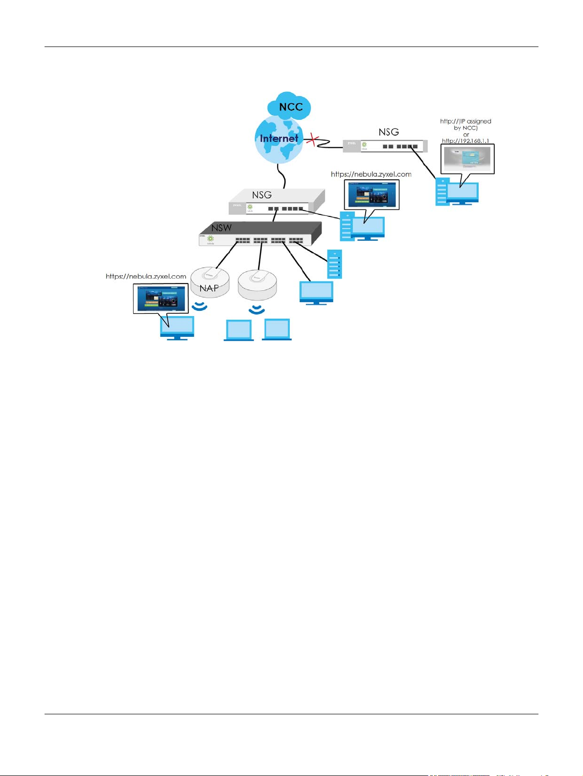
Web Configurator
The built-in Web Configurator allows basic NSG setup and monitoring using an Internet browser. This
User’s Guide provides information about the Web Configurator.
Figure 1 Managing the NSG: Web Configurator
1.4 Good Habits for Managing the NSG
Do the following things to make the NSG more secure and to manage it more effectively.
• Change the NSG’s system password through the NCC occasionally. Use a password that’s not easy to
guess and that consists of different types of characters, such as numbers and letters.
• Write down the password and put it in a safe place.
NSG Series User’s Guide
7
This chapter describes the front panels and rear panels of the NSG and shows you how to make the
hardware connections.
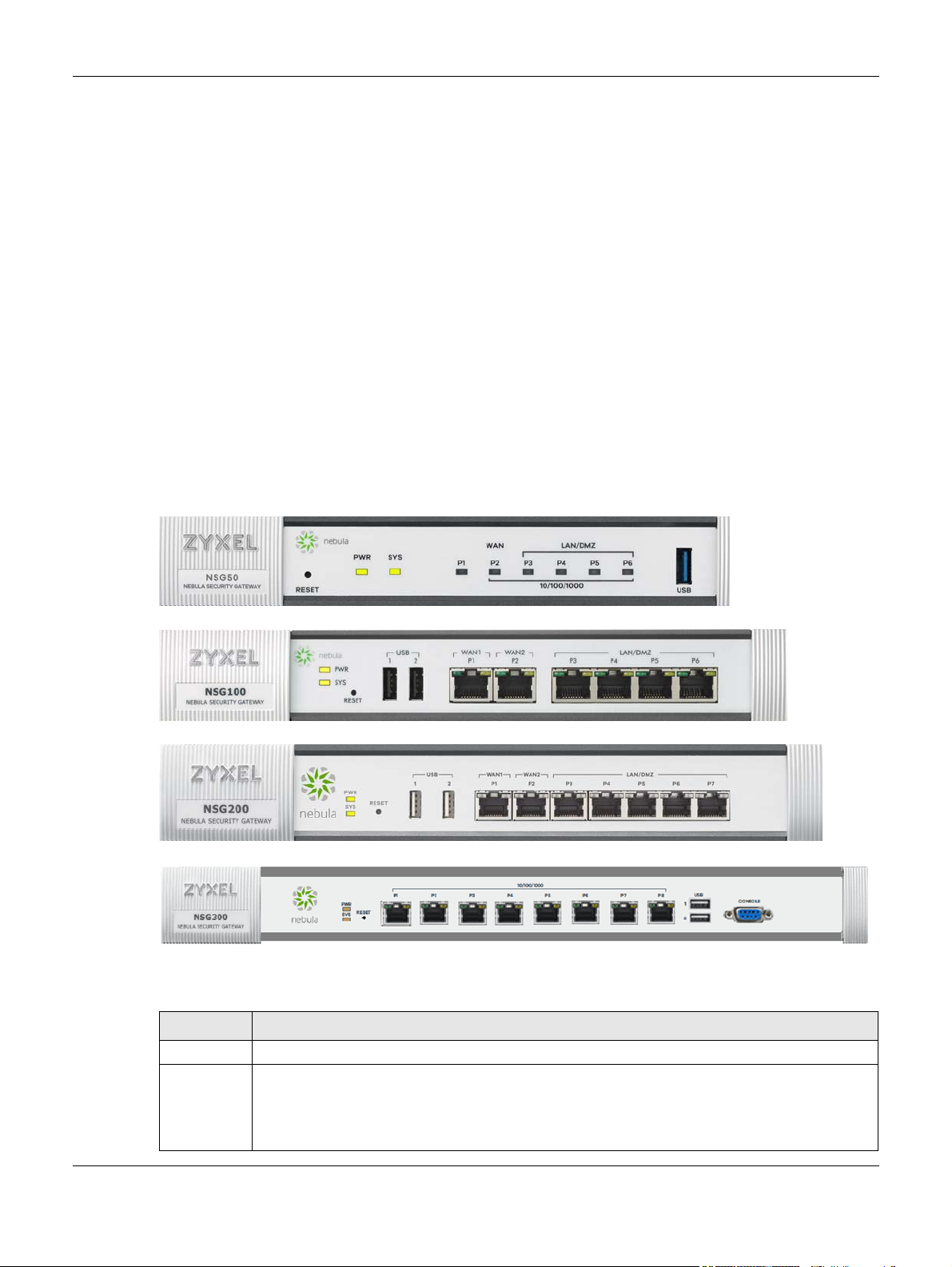
2.1 Front Panels
The figures below show the front panels of the NSG.
Figure 2 NSG50
Chapter 2 Hardware Panels
CHAPTER 2
Hardware Panels
Figure 3 NSG100
Figure 4 NSG200
Figure 5 NSG300
The following table describes the items on the front panels.
Table 2 Panel Ports and Buttons
LABEL DESCRIPTION
Reset Press the button to return the NSG to the factory defaults.
USB Connect a USB storage device to the USB port to store the following:
• Packet capture files
• Diagnostic information
•System logs
NSG Series User’s Guide
8
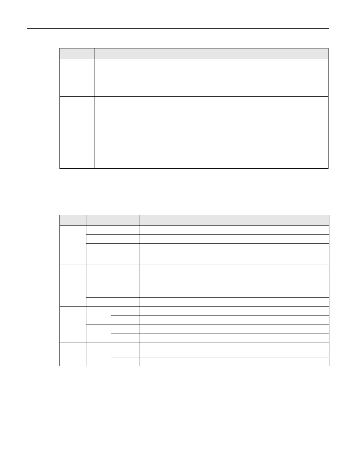
Table 2 Panel Ports and Buttons (continued)
LABEL DESCRIPTION
WAN 1-2
P1-P2
(NSG100/
NSG200/
NSG300)
LAN
P3-P6
(NSG100)
P3-P7
(NSG200)
P3-P8
(NSG300)
CONSOLE Connect your computer to the CONSOLE port using an Ethernet or DB-9 cable to manage the NSG
2.1.1 LEDs (Lights)
Chapter 2 Hardware Panels
Connect an Ethernet cable to the Ethernet WAN port for Internet access.
Connect computers or other Ethernet devices to Ethernet ports for Internet access.
using CLI commands. You will be prompted to enter your user name and password.
The following are LED descriptions for the NSG series models.
Table 3 NSG50/100/200/300 LED Descriptions
LED COLOR STATUS DESCRIPTION
PWR Off The NSG is turned off.
Green On The NSG is turned on.
Red On There is a hardware component failure. Shut down the device, wait for a few
minutes and then restart the device. If the LED turns red again, then please
contact your vendor.
SYS Green Off The NSG is not ready or has failed.
On The NSG is ready and running.
Blinking The NSG is booting, connected to the NCC but not registered, or searching for
Red On The NSG encountered an error or has failed.
P1, P2... Green Off There is no traffic on this port.
Blinking The NSG is sending or receiving packets on this port.
Orange Off There is no connection on this port.
On This port has a successful link.
USB Green Off No device is connected to the NSG’s USB port or the connected device is not
On A USB storage device is connected to the USB port.
(discovering) the NCC.
supported by the NSG.
2.2 Rear Panels
The figures below show the rear panels of the NSG.
NSG Series User’s Guide
9
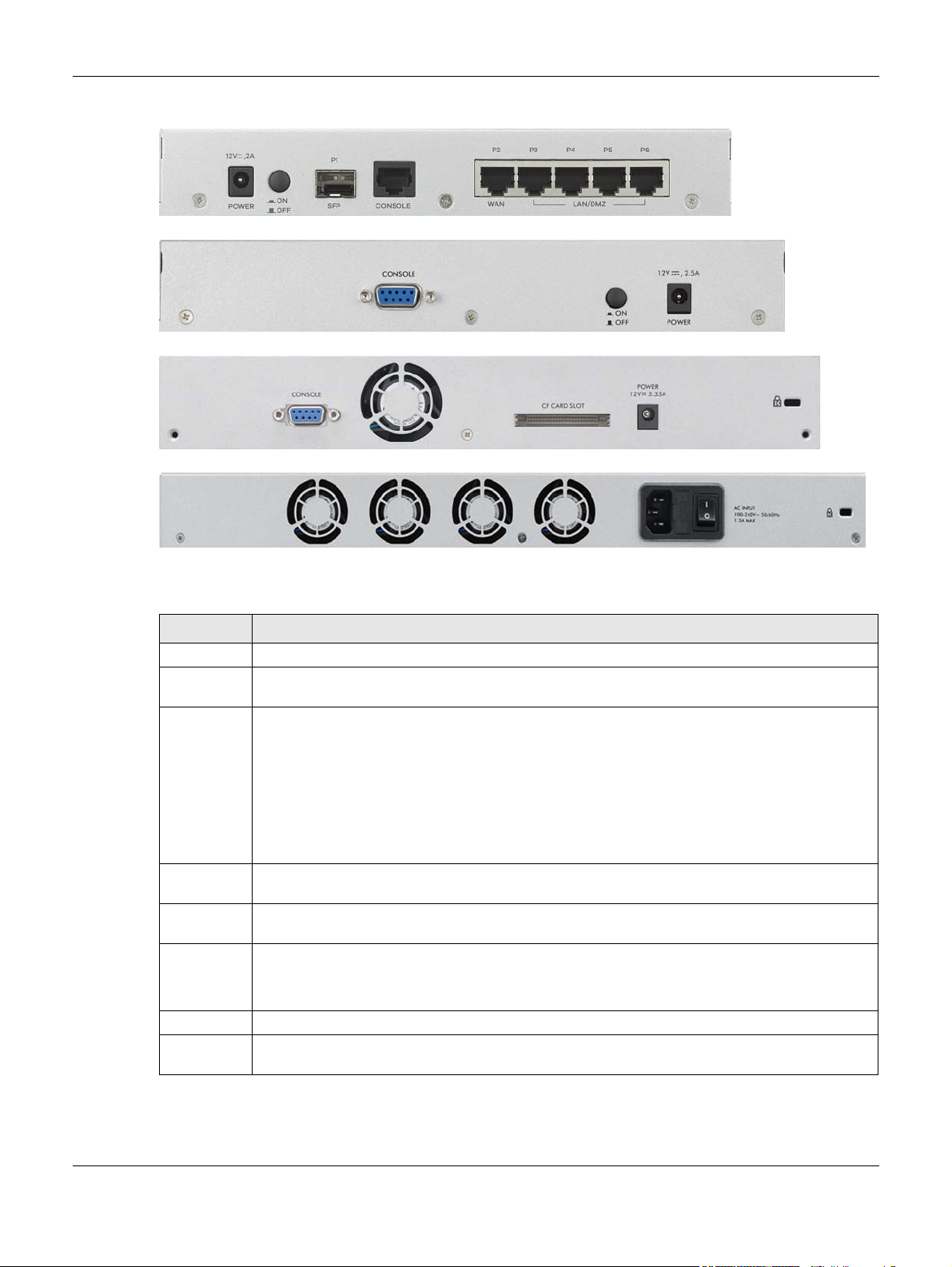
Figure 6 NSG50
Figure 7 NSG100
Figure 8 NSG200
Figure 9 NSG300
Chapter 2 Hardware Panels
The following table describes the items on the rear panels.
Table 4 Panel Ports and Buttons
LABEL DESCRIPTION
POWER Connect the power cable and press the power button to start the NSG.
Power
Button
SFP
P1/WAN 2
(NSG50)
CONSOLE Connect your computer to the CONSOLE port using an Ethernet or DB-9 cable to manage the NSG
P2/WAN 1
(NSG50)
LAN
P3-P6
(NSG50)
Fan The fans are for cooling the NSG. Make sure they are not obstructed to allow maximum ventilation.
Lock Attach a lock-and-cable from the Kensington lock (the small, metal-reinforced, oval hole) to a
Press the power button after the power cable is connected to start the NSG.
This is an SFP (1G) port. These are compatible 1G transceiver modules (at the time of writing):
• SFP-1000T
•SFP-SX-D
• SFP-LX-10-D
• SFP-BX1310-10-D
• SFP-BX1490-10-D
• SFP-LHX1310-40-D
• SFP-ZX-80-D
using CLI commands. You will be prompted to enter your user name and password.
Connect an Ethernet cable to the Ethernet WAN port for Internet access.
LAN: Connect computers or other Ethernet devices to Ethernet ports for Internet access.
permanent object, such as a pole, to secure the NSG in place.
NSG Series User’s Guide
10
Chapter 3 The Web Configurator
CHAPTER 3
The Web Configurator
See Section 1.1 on page 5 to see when you need to use the Web Configurator.
In order to use the Web Configurator, you must:
• Use one of the following web browser versions or later: Internet Explorer 10.0 and later versions, Mozilla
Firefox 36.0 and later versions, Safari 9.0 and later versions, or Google Chrome 38.0 and later versions
• Allow pop-up windows (blocked by default in Windows XP Service Pack 2)
• Enable JavaScripts, Java permissions, and cookies
The recommended screen resolution is 1024 x 768 pixels.
3.0.1 Web Configurator Access
1 Make sure your NSG hardware is properly connected. See the Quick Start Guide.
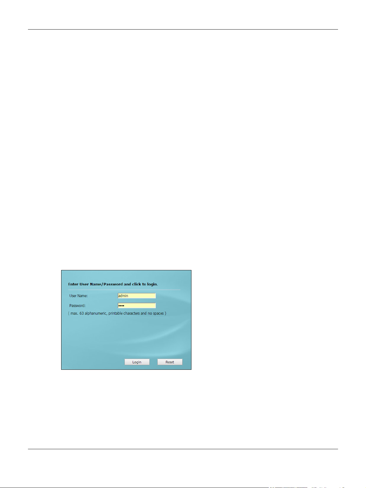
2 In your browser go to http://(IP assigned by NCC) or http://192.168.1.1. See Section 1.1 on page 5 for
more information. By default, the NSG automatically routes this request to its HTTPS server, and it is
recommended to keep this setting. The Login screen appears.
3 Type the user name (default: “admin”) and password (default: “1234”). If the NSG is being managed or
has been managed by the NCC, check the NCC's Site-Wide > Configure > General setting screen for
the NSG's current password.
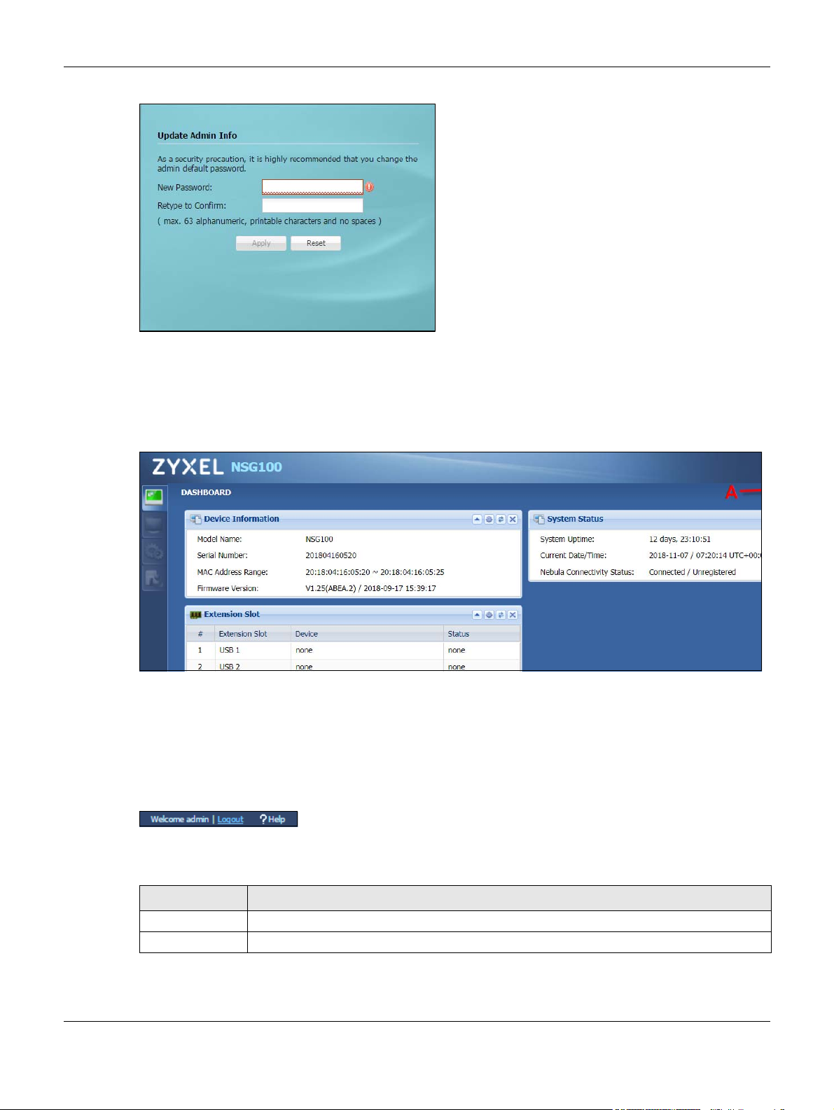
4 Click Login. After you log in for the first time using the default user name and password, you must
change the default admin password in the Update Admin Info screen. Type a new password of up to 63
printable characters without spaces, then click Apply.
NSG Series User’s Guide
11
Chapter 3 The Web Configurator
5 The Login screen appears after you click Apply.
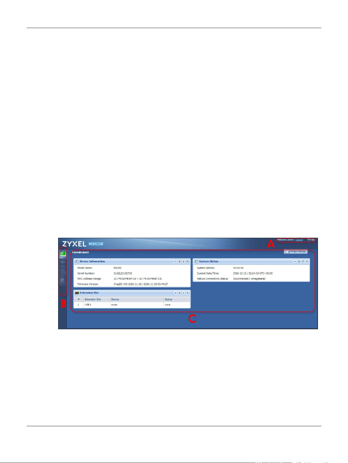
3.0.2 Web Configurator Screens Overview
The Web Configurator screen is divided into these parts :
• A - title bar
• B - navigation panel
• C - main window
Title Bar
Figure 10 Title Bar
The title bar icons in the upper right corner provide the following functions.
Table 5 Title Bar: Web Configurator Icons
LABEL DESCRIPTION
Logout Click this to log out of the Web Configurator.
Help Click this to open the help page for the current screen.
NSG Series User’s Guide
12
3.0.3 Navigation Panel
Use the navigation panel menu items to open status and configuration screens. The following sections
introduce the NSG’s navigation panel menus and their screens.
Dashboard
The dashboard displays general device information, system status, and extension slot status in widgets
that you can re-arrange to suit your needs. Extension slot shows whether there’s a USB device
connected to the NSG.
Monitor Menu
The monitor menu screens display status and information about the connected USB device.
Table 6 Monitor Menu Screens Summary
FOLDER OR LINK TAB FUNCTION
USB Storage Storage
Information
Chapter 3 The Web Configurator
Displays details about a USB device connected to the NSG.
Configuration Menu
Use the configuration menu screens to configure the NSG’s features.
Table 7 Configuration Menu Screens Summary
FOLDER OR LINK TAB FUNCTION
Interface Ethernet Manage Ethernet interfaces and virtual Ethernet interfaces.
SSH SSH Configure SSH server and SSH service settings.
User User Manage the user account “admin”.
USB Storage Settings Configure the settings for a connected USB device.
Maintenance Menu
Use the maintenance menu screens to run diagnostics for troubleshooting, capture network traffic to
identify network problems, and ping or traceroute an IP address.
Table 8 Maintenance Menu Screens Summary
FOLDER
OR LINK
Diagnostics Diagnostics Collect diagnostic information.
TAB FUNCTION
Packet Capture Capture packets for analysis.
Network Tool Identify problems with connections. You can use Ping or TraceRoute to help you
identify problems.
3.0.4 Tables and Lists
Web Configurator tables and lists are flexible with several options for how to display their entries.
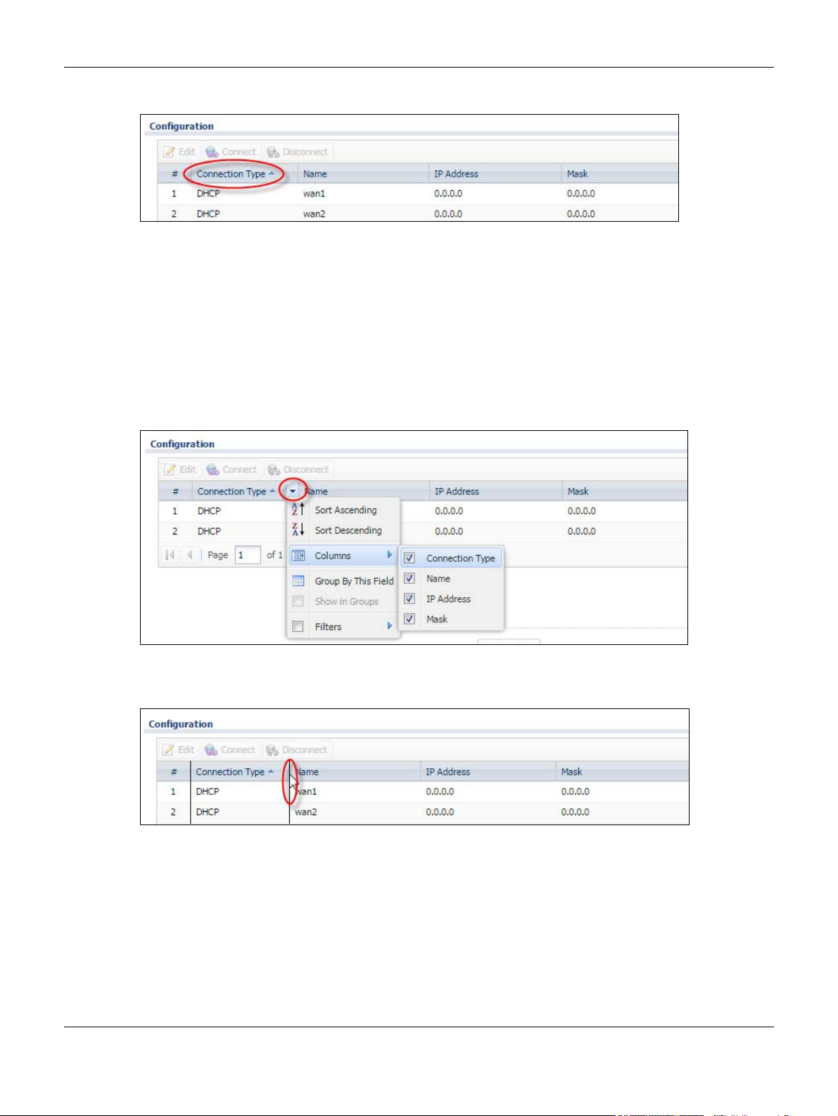
Click a column heading to sort the table’s entries according to that column’s criteria.
NSG Series User’s Guide
13
Chapter 3 The Web Configurator
Figure 11 Sorting Table Entries by a Column’s Criteria
Click the down arrow next to a column heading for more options about how to display the entries. The
options available vary depending on the type of fields in the column. Here are some examples of what
you can do:
• Sort in ascending or descending (reverse) alphabetical order
• Select which columns to display
•Group entries by field
• Show entries in groups
• Filter by mathematical operators (<, >, or =) or searching for text
Figure 12 Common Table Column Options
Select a column heading cell’s right border and drag to re-size the column.
Figure 13 Resizing a Table Column
Select a column heading and drag and drop it to change the column order. A green check mark
displays next to the column’s title when you drag the column to a valid new location.
NSG Series User’s Guide
14
Chapter 3 The Web Configurator
Figure 14 Moving Columns
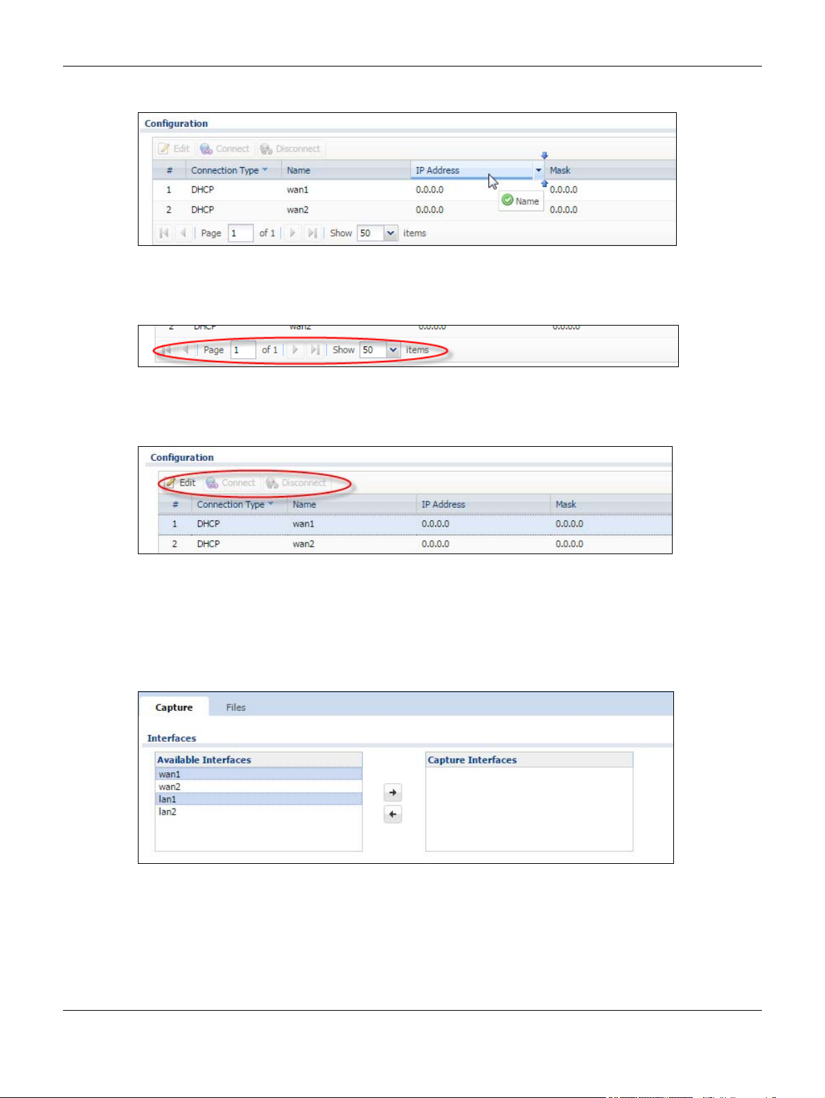
Use the icons and fields at the bottom of the table to navigate to different pages of entries and control
how many entries display at a time.
Figure 15 Navigating Pages of Table Entries
The tables have icons for working with table entries. You can often use the [Shift] or [Ctrl] key to select
multiple entries to remove, activate, or deactivate.
Figure 16 Table Icons
Working with Lists
When a list of available entries displays next to a list of selected entries, you can often just double-click
an entry to move it from one list to the other. In some lists you can also use the [Shift] or [Ctrl] key to
select multiple entries, and then use the arrow button to move them to the other list.
Figure 17 Working with Lists
NSG Series User’s Guide
15
4.1 Overview
Use the Dashboard screens to check status information about the NSG.
4.1.1 What You Can Do in this Chapter
Use the main Dashboard screen to see the NSG’s general device information, system status, and
extension slot status. You can also display other status screens for more information.
4.2 Dashboard Screen
CHAPTER 4
Dashboard
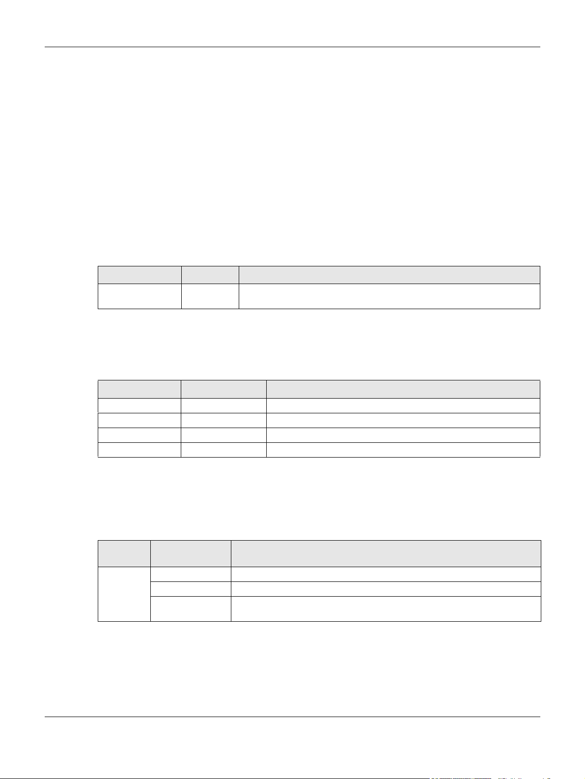
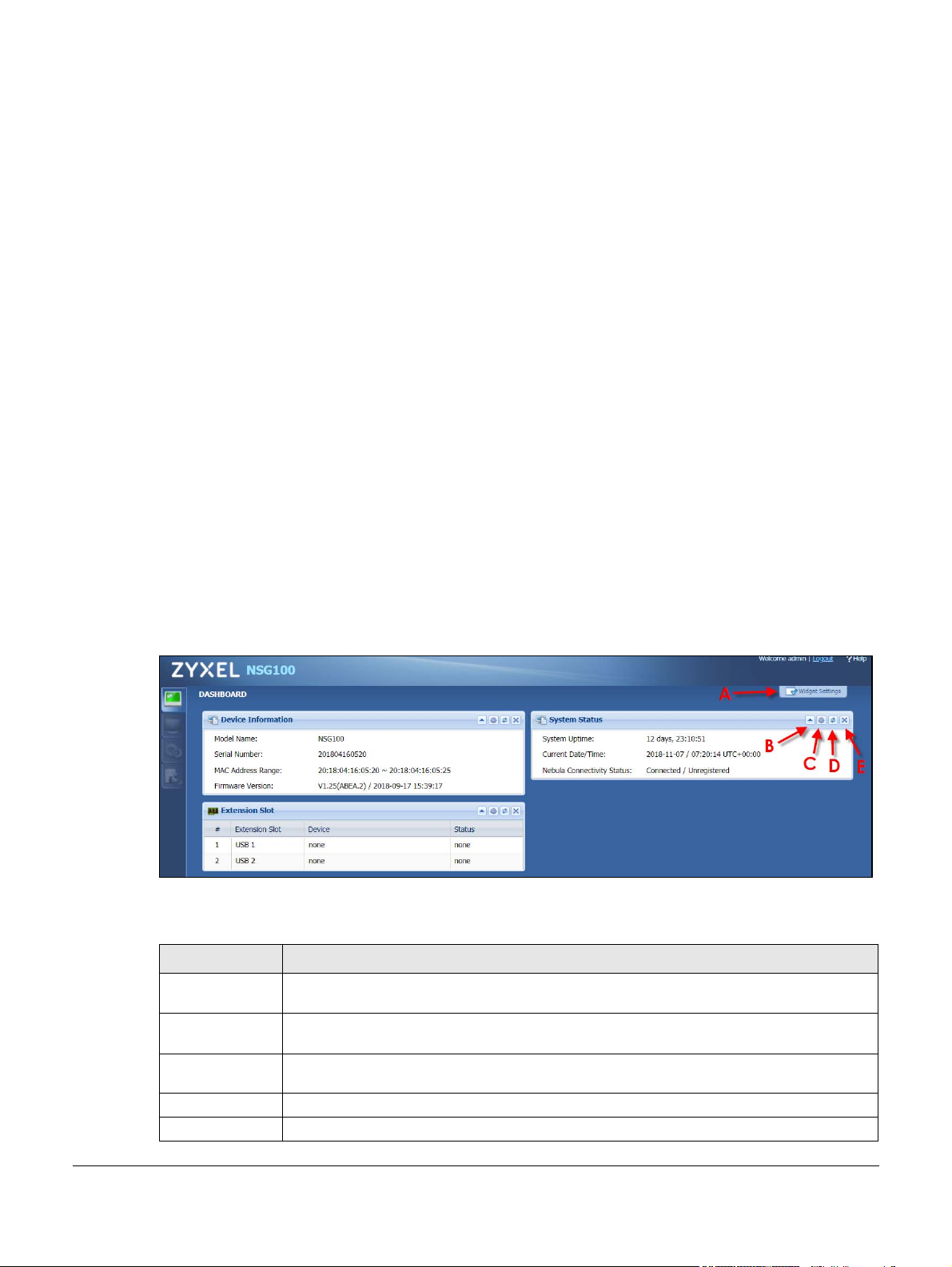
The Dashboard screen displays when you log into the NSG or click Dashboard in the navigation panel.
The dashboard displays general device information, system status, and extension slot status in widgets
that you can re-arrange to suit your needs. You can also collapse, refresh, and close individual widgets.
Figure 18 Dashboard
The following table describes the labels in this screen.
Table 9 Dashboard
LABEL DESCRIPTION
Widget Settings
(A)
Up Arrow (B) Click this to collapse a widget. It then becomes a down arrow. Click it again to enlarge the
Refresh Time
Setting (C)
Refresh Now (D) Click this to update the widget’s information immediately.
Close Widget (E) Click this to close the widget. Use Widget Settings to re-open it.
Use this link to open or close widgets by selecting/clearing the associated checkbox.
widget again.
Set the interval for refreshing the information displayed in the widget.
NSG Series User’s Guide
16
Chapter 4 Dashboard
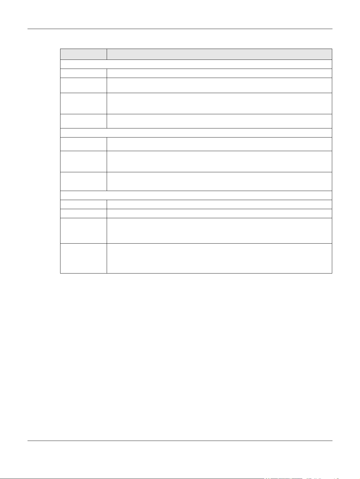
Table 9 Dashboard (continued)
LABEL DESCRIPTION
Device Information
Model Name This field displays the model name of this NSG.
Serial Number This field displays the serial number of this NSG. The serial number is used for device tracking
and control.
MAC Address
Range
Firmware
Version
System Status
System
Uptime
Current Date/
Time
Nebula
Connectivity
Status
Extension Slot
# This field is a sequential value, and it is not associated with a specific entry.
Extension Slot This field displays the name of each extension slot.
Device This field displays the name of the device connected to the extension slot (or none if no device
This field displays the MAC addresses used by the NSG. Each physical port has one MAC
address. The first MAC address is assigned to physical port 1, the second MAC address is
assigned to physical port 2, and so on.
This field displays the version number and date of the firmware the NSG is currently running.
This field displays how long the NSG has been running since it last restarted or was turned on.
This field displays the current date and time in the NSG. The format is yyyy-mm-dd hh:mm:ss.
Click on the link to see the Date/Time screen where you can make edits and changes to the
date, time and time zone information.
This field displays whether the NSG is registered and can connect to the Zyxel Nebula Control
Center (NCC).
is detected).
USB Flash Drive - Indicates a connected USB storage device and the drive’s storage capacity.
Status This field displays none if no device is detected.
Ready - A USB storage device connected to the NSG is ready for the NSG to use.
Unused - The NSG is unable to mount a USB storage device connected to the NSG.
NSG Series User’s Guide
17

5.1 Overview
Use the Monitor screens to check status and information about the connected USB device.
5.2 USB Storage Screen
This screen displays information about a connected USB storage device. Click Monitor > USB Storage to
display this screen.
Figure 19 Monitor > USB Storage
CHAPTER 5
Monitor
The following table describes the labels in this screen.
Table 10 Monitor > USB Storage
LABEL DESCRIPTION
Device Description This is a basic description of the type of USB device.
Usage This field displays how much of the USB storage device’s capacity is currently being
used out of its total capacity and what percentage that makes.
File System This field displays what file system the USB storage device is formatted with. This field
displays Unknown if the file system of the USB storage device is not supported by the
NSG, such as NTFS.
Use a USB storage device that supports the FAT16, FAT32, EXT2, or EXT3 file system.
Speed This field displays the connection speed the USB storage device supports.
NSG Series User’s Guide
18

Chapter 5 Monitor
Table 10 Monitor > USB Storage (continued)
LABEL DESCRIPTION
Status Ready - you can have the NSG use the USB storage device.
Click Remove Now to stop the NSG from using the USB storage device so you can
remove it.
Unused - the connected USB storage device was manually unmounted by using the
Remove Now button or for some reason the NSG cannot mount it.
Click Use It to have the NSG mount a connected USB storage device. This button is
grayed out if the file system is not supported (unknown) by the NSG.
none - no USB storage device is connected.
Detail This field displays any other information the NSG retrieves from the USB storage device.
• Deactivated - the use of a USB storage device is disabled (turned off) on the NSG.
• OutofSpace - the available disk space is less than the disk space full threshold.
• Mounting - the NSG is mounting the USB storage device.
• Removing - the NSG is unmounting the USB storage device.
• none - the USB device is not connected.
NSG Series User’s Guide
19

6.1 Overview
Use the Interface screen to configure the NSG’s WAN interfaces.
6.2 Ethernet
This screen lists the WAN Ethernet interfaces on the NSG. To access this screen, click Configuration >
Interface > Ethernet.
You cannot create new Ethernet interfaces nor can you delete any of them. Ethernet interfaces have
an IP address, subnet mask, and gateway used to make routing decisions.
CHAPTER 6
Configuration
Figure 20 Configuration > Interface > Ethernet
Each field is described in the following table.
Table 11 Configuration > Interface > Ethernet
LABEL DESCRIPTION
Edit Double-click an entry or select it and click Edit to open a screen where you can modify the
entry’s settings.
Connect To connect an interface, select it and click Connect. You might use this in testing the
Disconnect To disconnect an interface, select it and click Disconnect. You might use this in testing the
# This field is a sequential value, and it is not associated with any interface.
Connection Type This field displays the connection type (DHCP, Ethernet Fixed IP, PPPoE) of the interface.
Name This field displays the name of the interface.
IP Address This field displays the current IP address of the interface. If the IP address is 0.0.0.0 (in the IPv4
interface or to manually establish the connection.
interface.
network), the interface does not have an IP address yet.
NSG Series User’s Guide
20

Table 11 Configuration > Interface > Ethernet (continued)
LABEL DESCRIPTION
Mask This field displays the interface’s subnet mask in dot decimal notation.
Reset Click Reset to return the screen to its last-saved settings.
6.2.1 Ethernet Edit
The Ethernet Edit screen lets you configure IP address assignment. To access this screen, select an
interface and click its Edit icon in the Ethernet screen. (See Section 6.2 on page 20.)
The screen varies depending on the connection type (DHCP, Ethernet Fixed IP, PPPoE) you select.
DHCP
Select DHCP to set this interface to act as a DHCP client and automatically get the WAN IP address,
subnet mask, gateway address and DNS server information from a DHCP server.
Figure 21 Configuration > Interface > Ethernet > Edit (DHCP)
Chapter 6 Configuration
Ethernet Fixed IP
Select Ethernet Fixed IP if your ISP assigned you a fixed IP address and DNS server information. Specify
the IP address, subnet mask, gateway and DNS server address manually.
NSG Series User’s Guide
21

Chapter 6 Configuration
Figure 22 Configuration > Network > Interface > Ethernet > Edit (Ethernet Fixed IP)
PPPoE
Select PPPoE if the interface is connecting to the Internet using a dial-up connection with a user name
and password. This way, you do not have to install or manage PPPoE software on each computer in the
network.
• Select an authentication protocol for outgoing connection requests. Options are:
• CHAP/PAP - Your NSG accepts either CHAP or PAP when requested by the remote node.
• CHAP - Your NSG accepts CHAP only.
• PAP - Your NSG accepts PAP only.
• MSCHAP - Your NSG accepts MSCHAP only.
• MSCHAP-V2 - Your NSG accepts MSCHAP-V2 only.
• Enter the user name and password given to you by your ISP.
•Select Nailed-Up if you do not want the connection to time out.
Configuration > Network > Interface > Ethernet > Edit (Internal Type)
Figure 23 Configuration > Network > Interface > Ethernet > Edit (PPPoE)
NSG Series User’s Guide
22

6.3 SSH
You can use SSH (Secure SHell) to securely access the NSG’s command line interface. Specify from
which IP address the access can come.
SSH is a secure communication protocol that combines authentication and data encryption to provide
secure encrypted communication between two hosts over an unsecured network. In the following
figure, computer A on the Internet uses SSH to securely connect to the WAN port of the NSG for a
management session.
Figure 24 SSH Communication Over the WAN Example
6.3.1 How SSH Works
The following figure is an example of how a secure connection is established between two remote hosts
using SSH v1.
Chapter 6 Configuration
Figure 25 How SSH v1 Works Example
NSG Series User’s Guide
23

Chapter 6 Configuration
1 Host Identification
The SSH client sends a connection request to the SSH server. The server identifies itself with a host key. The
client encrypts a randomly generated session key with the host key and server key and sends the result
back to the server.
The client automatically saves any new server public keys. In subsequent connections, the server public
key is checked against the saved version on the client computer.
2 Encryption Method
Once the identification is verified, both the client and server must agree on the type of encryption
method to use.
3 Authentication and Data Transmission
After the identification is verified and data encryption activated, a secure tunnel is established between
the client and the server. The client then sends its authentication information (user name and password)
to the server to log in to the server.
6.3.2 SSH Implementation on the NSG
Your NSG supports SSH versions 1 and 2 using RSA authentication and four encryption methods (AES,
3DES, Archfour, and Blowfish). The SSH server is implemented on the NSG for management using port 22
(by default).
6.3.3 Requirements for Using SSH
You must install an SSH client program on a client computer (Windows or Linux operating system) that is
used to connect to the NSG over SSH.
6.3.4 Configuring SSH
Click Configuration > SSH to change your NSG’s Secure Shell settings. Use this screen to specify from
which IP address the access can come.
Figure 26 Configuration > SSH
NSG Series User’s Guide
24

Chapter 6 Configuration
The following table describes the labels in this screen.
Table 12 Configuration > SSH
LABEL DESCRIPTION
Allow WAN to
Device
Client IP Address Enter the IP address with which the computer is allowed to access.
Apply Click Apply to save your changes back to the NSG.
Reset Click Reset to return the screen to its last-saved settings.
Select the check box to allow the computer with the IP address that matches the IP address in
the Client IP Address field to access the NSG CLI using SSH.
6.3.5 Secure Telnet Using SSH Examples
This section shows two examples using a command interface and a graphical interface SSH client
program to remotely access the NSG. The configuration and connection steps are similar for most SSH
client programs. Refer to your SSH client program user’s guide.
6.3.5.1 Example 1: Microsoft Windows
This section describes how to access the NSG using the Secure Shell Client program.
1 Launch the SSH client and specify the connection information (IP address, port number) for the NSG.
2 Configure the SSH client to accept connection using SSH version 1.
3 A window displays prompting you to store the host key in you computer. Click Yes to continue.
Figure 27 SSH Example 1: Store Host Key
Enter the password to log in to the NSG. The CLI screen displays next.
6.3.5.2 Example 2: Linux
This section describes how to access the NSG using the OpenSSH client program that comes with most
Linux distributions.
1 Test whether the SSH service is available on the NSG.
Enter “telnet 192.168.1.1 22” at a terminal prompt and press [ENTER]. The computer attempts to
connect to port 22 on the NSG (using the default IP address of 192.168.1.1).
A message displays indicating the SSH protocol version supported by the NSG.
NSG Series User’s Guide
25

Chapter 6 Configuration
Figure 28 SSH Example 2: Test
$ telnet 192.168.1.1 22
Trying 192.168.1.1...
Connected to 192.168.1.1.
Escape character is '^]'.
SSH-1.5-1.0.0
2 Enter “ssh –1 192.168.1.1”. This command forces your computer to connect to the NSG using SSH
version 1. If this is the first time you are connecting to the NSG using SSH, a message displays prompting
you to save the host information of the NSG. Type “yes” and press [ENTER].
Then enter the password to log in to the NSG.
Figure 29 SSH Example 2: Log in
$ ssh –1 192.168.1.1
The authenticity of host '192.168.1.1 (192.168.1.1)' can't be established.
RSA1 key fingerprint is 21:6c:07:25:7e:f4:75:80:ec:af:bd:d4:3d:80:53:d1.
Are you sure you want to continue connecting (yes/no)? yes
Warning: Permanently added '192.168.1.1' (RSA1) to the list of known hosts.
Administrator@192.168.1.1's password:
3 The CLI screen displays next.
6.4 User
Use this screen to change your password of the user account “admin”. It is strongly recommended that
you change your NSG's password. To access this screen, click Configuration > User.
Note: The NSG’s login password is overwritten with what you have configured in the NCC
Figure 30 Configuration > User
when the NSG is managed by the NCC.
NSG Series User’s Guide
26

Each field is described in the following table.
Table 13 Configuration > User
LABEL DESCRIPTION
Password Type your new system password (up to 63 ASCII characters). Note that as you type a
Retype Retype your new password for confirmation.
Apply Click Apply to save your changes back to the NSG.
Reset Click Reset to return the screen to its last-saved settings.
6.5 USB Storage
The NSG can use a connected USB device to store the packet capture files and diagnostic information.
Use this screen to turn on this feature and set a disk full warning limit.
Note: Only connect one USB device. It must allow writing (it cannot be read-only) and use the
FAT16, FAT32, EXT2, or EXT3 file system.
Chapter 6 Configuration
password, the screen displays a dot (.) for each character you type.
Click Configuration > USB Storage to open the screen as shown next.
Figure 31 Configuration > USB Storage
The following table describes the labels in this screen.
Table 14 Configuration > USB Storage
LABEL DESCRIPTION
Activate USB
storage service
Disk full warning
when remaining
space is less than
Save traffic log
data to USB
storage
Select this if you want to use the connected USB device(s).
Set a number and select a unit (MB or %) to have the NSG send a warning message when the
remaining USB storage space is less than the value you set here.
If the USB storage device runs out of space, the NSG will stop storing the packet capture files
and diagnostic information on the USB storage device.
Select this to store traffic and system logs on the connected USB storage device.
NSG Series User’s Guide
27

Chapter 6 Configuration
Table 14 Configuration > USB Storage (continued)
LABEL DESCRIPTION
Apply Click Apply to save your changes back to the NSG.
Reset Click Reset to return the screen to its last-saved settings.
NSG Series User’s Guide
28

7.1 Diagnostics Overview
Use the diagnostics screens for troubleshooting.
7.2 Diagnostics Screen
The Diagnostics screen provides an easy way for you to generate a file containing the NSG’s
configuration and diagnostic information. You may need to send this file to customer support for
troubleshooting.
Click Maintenance > Diagnostics to open the Diagnostic screen.
CHAPTER 7
Maintenance
Figure 32 Maintenance > Diagnostics
The following table describes the labels in this screen.
Table 15 Maintenance > Diagnostics
LABEL DESCRIPTION
Filename This is the name of the most recently created diagnostic file.
Last Modified This is the date and time that the last diagnostic file was created. The format is yyyy-
mm-dd hh:mm:ss.
Size This is the size of the most recently created diagnostic file.
Copy the diagnostic file to
USB storage (if ready)
Select this to have the NSG create an extra copy of the diagnostic file to a
connected USB storage device.
NSG Series User’s Guide
29

Table 15 Maintenance > Diagnostics
LABEL DESCRIPTION
Apply Click Apply to save your changes.
Collect Now Click this to have the NSG create a new diagnostic file.
Wait while information is collected.
7.2.1 Diagnostics Files Screen
Click Maintenance > Diagnostics > Files to open the diagnostic files screen. This screen lists the files of
diagnostic information the NSG has collected and stored in the NSG or a connected USB storage
device. You may need to send these files to customer support for troubleshooting.
Chapter 7 Maintenance
Figure 33 Maintenance > Diagnostics > Files
The following table describes the labels in this screen.
Table 16 Maintenance > Diagnostics > Files
LABEL DESCRIPTION
Remove Select files and click Remove to delete them from the NSG or the connected USB storage device.
Use the [Shift] and/or [Ctrl] key to select multiple files. A pop-up window asks you to confirm that
you want to delete.
Download Click a file to select it and click Download to save it to your computer.
# This column displays the number for each file entry. The total number of files that you can save
depends on the file sizes and the available storage space.
File Name This column displays the label that identifies the file.
Size This column displays the size (in bytes) of a file.
Last Modified This column displays the date and time that the individual files were saved.
NSG Series User’s Guide
30

Chapter 7 Maintenance
7.3 Packet Capture Screen
Use this screen to capture network traffic going through the NSG’s interfaces. Studying these packet
captures may help you identify network problems. Click Maintenance > Diagnostics > Packet Capture to
open the packet capture screen.
Note: New capture files overwrite existing files of the same name. Change the File Suffix field’s
setting to avoid this.
Figure 34 Maintenance > Diagnostics > Packet Capture
The following table describes the labels in this screen.
Table 17 Maintenance > Diagnostics > Packet Capture
LABEL DESCRIPTION
Interfaces Enabled interfaces (except for virtual interfaces) appear under Available Interfaces.
Select interfaces for which to capture packets and click the right arrow button to move
them to the Capture Interfaces list. Use the [Shift] and/or [Ctrl] key to select multiple
objects.
Filter
NSG Series User’s Guide
31

Chapter 7 Maintenance
Table 17 Maintenance > Diagnostics > Packet Capture (continued)
LABEL DESCRIPTION
IP Version Select the version of IP for which to capture packets. Select any to capture packets for
all IP versions.
Protocol Type Select the protocol of traffic for which to capture packets. Select any to capture
Host IP Select a host IP address object for which to capture packets. Select any to capture
Host Port This field is configurable when you set the IP Type to any, tcp, or udp. Specify the port
Misc setting
Continuously capture
and overwrite old ones
Captured Packet Files When saving packet captures only to the NSG’s onboard storage, specify a maximum
packets for all types of traffic.
packets for all hosts. Select User Defined to be able to enter an IP address.
number of traffic to capture.
Select this to have the NSG keep capturing traffic and overwriting old packet capture
entries when the available storage space runs out.
limit in megabytes for the total combined size of all the capture files on the NSG.
When saving packet captures to a connected USB storage device, specify a maximum
limit in megabytes for each capture file.
Note: If you have existing capture files and have not selected the
Continuously capture and overwrite old ones option, you may need to
set this size larger or delete existing capture files.
The valid range depends on the available onboard/USB storage size. The NSG stops the
capture and generates the capture file when either the file reaches this size or the time
period specified in the Duration field expires.
Split threshold Specify a maximum size limit in megabytes for individual packet capture files. After a
Duration Set a time limit in seconds for the capture. The NSG stops the capture and generates the
File Suffix Specify text to add to the end of the file name (before the dot and filename extension)
Number of Bytes to
Capture (Per Packet)
Save data to onboard
storage only
packet capture file reaches this size, the NSG starts another packet capture file.
capture file when either this period of time has passed or the file reaches the size
specified in the File Size field. 0 means there is no time limit.
to help you identify the packet capture files. Modifying the file suffix also avoids making
new capture files that overwrite existing files of the same name.
The file name format is “interface name-file suffix.cap”, for example “vlan2-packetcapture.cap”.
Specify the maximum number of bytes to capture per packet. The NSG automatically
truncates packets that exceed this size. As a result, when you view the packet capture
files in a packet analyzer, the actual size of the packets may be larger than the size of
captured packets.
Select this to have the NSG only store packet capture entries on the NSG. The available
storage size is displayed as well.
Note: The NSG reserves some onboard storage space as a buffer.
NSG Series User’s Guide
32

Chapter 7 Maintenance
Table 17 Maintenance > Diagnostics > Packet Capture (continued)
LABEL DESCRIPTION
Save data to USB
storage
Select this to have the NSG store packet capture entries only on a USB storage device
connected to the NSG if the NSG allows this.
Status:
Unused - the connected USB storage device was manually unmounted by using the
Remove Now button or for some reason the NSG cannot mount it.
none - no USB storage device is connected.
service deactivated - USB storage feature is disabled (in Configuration > Object > USB
Storage), so the NSG cannot use a connected USB device to store system logs and other
diagnostic information.
available - you can have the NSG use the USB storage device. The available storage
capacity also displays.
Note: The NSG reserves some USB storage space as a buffer.
Capture Click this button to have the NSG capture packets according to the settings configured
in this screen.
You can configure the NSG while a packet capture is in progress although you cannot
modify the packet capture settings.
The NSG’s throughput or performance may be affected while a packet capture is in
progress.
After the NSG finishes the capture it saves a separate capture file for each selected
interface. The total number of packet capture files that you can save depends on the
file sizes and the available flash storage space. Once the flash storage space is full,
adding more packet captures will fail.
Stop Click this button to stop a currently running packet capture and generate a separate
Reset Click this button to return the screen to its last-saved settings.
capture file for each selected interface.
7.3.1 Packet Capture Files Screen
Click Maintenance > Diagnostics > Packet Capture > Files to open the packet capture files screen. This
screen lists the files of packet captures stored on the NSG or a connected USB storage device. You can
download the files to your computer where you can study them using a packet analyzer (also known as
a network or protocol analyzer) such as Wireshark.
NSG Series User’s Guide
33

Chapter 7 Maintenance
Figure 35 Maintenance > Diagnostics > Packet Capture > Files
The following table describes the labels in this screen.
Table 18 Maintenance > Diagnostics > Packet Capture > Files
LABEL DESCRIPTION
Remove Select files and click Remove to delete them from the NSG or the connected USB storage
device. Use the [Shift] and/or [Ctrl] key to select multiple files. A pop-up window asks you to
confirm that you want to delete.
Download Click a file to select it and click Download to save it to your computer.
# This column displays the number for each packet capture file entry. The total number of packet
capture files that you can save depends on the file sizes and the available flash storage space.
File Name This column displays the label that identifies the file. The file name format is interface name-file
suffix.cap.
Size This column displays the size (in bytes) of a configuration file.
Last Modified This column displays the date and time that the individual files were saved.
7.4 System Log Screen
Click Maintenance > Diagnostics > System Log to display this screen.
This screen lists the files of NSG system logs stored on a connected USB storage device. The files are in
comma separated value (csv) format. You can download them to your computer and open them in a
tool like Microsoft’s Excel.
Figure 36 Maintenance > Diagnostics > System Log
NSG Series User’s Guide
34

Chapter 7 Maintenance
The following table describes the labels in this screen.
Table 19 Maintenance > Diagnostics > System Log
LABEL DESCRIPTION
Remove Select files and click Remove to delete them from the NSG. Use the [Shift] and/or [Ctrl]
key to select multiple files. A pop-up window asks you to confirm that you want to
delete.
Download Click a file to select it and click Download to save it to your computer.
# This column displays the number for each file entry. The total number of files that you can
File Name This column displays the label that identifies the file.
Size This column displays the size (in bytes) of a file.
Last Modified This column displays the date and time that the individual files were saved.
save depends on the file sizes and the available storage space.
7.5 Network Tool Screen
Use this screen to ping or traceroute an IP address.
Click Maintenance > Diagnostics > Network Tool to display this screen.
Figure 37 Maintenance > Diagnostics > Network Tool
NSG Series User’s Guide
35

Chapter 7 Maintenance
The following table describes the labels in this screen.
Table 20 Maintenance > Diagnostics > Network Tool
LABEL DESCRIPTION
Network Tool Select PING IPv4 to ping the IP address that you entered.
Select TRACEROUTE IPv4 to perform the traceroute function. This determines the path a
packet takes to the specified computer.
Domain Name or IP
Address
Interface Select an interface through which the packet is transmitted.
Extension Option Enter the extended option if you want to use an extended ping or traceroute
Test Click this button to start to ping or run a traceroute.
Stop Click this button to terminate the current ping operation or traceroute.
Reset Click this button to return the screen to its last-saved settings.
Type the IPv4 address of a computer that you want to perform ping or traceroute in
order to test a connection.
command. For example, enter “-c count” (where count is the number of ping
requests) to set how many times the NSG pings the destination IP address, or enter “-w
waittime” (where waittime is a time period in seconds) to set how long the NSG waits
for a response to a probe before running another traceroute.
NSG Series User’s Guide
36

This chapter offers some suggestions to solve problems you might encounter.
None of the LEDs turn on.
Make sure that you have the power cord connected to the NSG and plugged in to an appropriate
power source. Make sure you have the NSG turned on. Check all cable connections.
If the LEDs still do not turn on, you may have a hardware problem. In this case, you should contact your
local vendor.
Cannot access the NSG from the LAN.
CHAPTER 8
Troubleshooting
• Check the cable connection between the NSG and your computer or switch.
• Ping the NSG from a LAN computer. Make sure your computer’s Ethernet card is installed and
functioning properly. Also make sure that its IP address is in the same subnet as the NSG’s.
• In the computer, click Start, (All) Programs, Accessories and then Command Prompt. In the
Command Prompt window, type "ping" followed by the NSG’s LAN IP address (192.168.1.1 is the
default) and then press [ENTER]. The NSG should reply.
• If you’ve forgotten the NSG’s password, use the RESET button. Press the button in for about 5 seconds
(or until the SYS LED starts to blink), then release it. It returns the NSG to the factory defaults (password
is 1234, LAN IP address 192.168.1.1 etc).
• If the NCC has managed the NSG, check the NCC's Site-Wide > Configure > General setting screen
for the NSG's current password and the NCC's Gateway > Configure > Interface addressing screen for
the NSG's current LAN IP address.
• If you’ve forgotten the NSG’s IP address, you can use the commands through the console port to
check it. Connect your computer to the CONSOLE port using a console cable. Your computer should
have a terminal emulation communications program (such as HyperTerminal) set to VT100 terminal
emulation, no parity, 8 data bits, 1 stop bit, no flow control and 115200 bps port speed.
I cannot access the Internet.
• Check the NSG’s connection to the Ethernet jack with Internet access. Make sure the Internet
gateway device (such as a DSL modem) is working properly.
• Make sure that you enter the correct settings in the Configuration > Interface > Ethernet screen. Use
the same case as provided by your ISP.
NSG Series User’s Guide
37

Chapter 8 Troubleshooting
My packet capture captured less than I wanted or failed.
The packet capture screen’s File Size sets a maximum size limit for the total combined size of all the
capture files on the NSG, including any existing capture files and any new capture files you generate. If
you have existing capture files you may need to set this size larger or delete existing capture files.
The NSG stops the capture and generates the capture file when either the capture files reach the File
Size or the time period specified in the Duration field expires.
My earlier packet capture files are missing.
New capture files overwrite existing files of the same name. Change the File Suffix field’s setting to avoid
this.
I cannot access the NCC portal.
• Check that you are using the correct URL:
• NCC: https://nebula.zyxel.com/
• Make sure your computer’s Ethernet card is installed and functioning properly.
• Check that you have Internet access. In your computer, click Start, (All) Programs, Accessories and
then Command Prompt. In the Command Prompt window, type ‘ping’ followed by a website such as
‘zyxel.com’. If you get a reply try to ping ‘nebula.zyxel.com’.
• Make sure you are using the correct web browser. Browsers supported are:
• Firefox 21 or later
• Chrome 26.0 or later
• IE 10 or later
• Internet Explorer 9.0 or later
• Safari 6.0 or later
I cannot log into the NCC portal.
• Open your web browser and go to https://portal.myzyxel.com. Sign in with the correct email and
password. Click Not a Member Yet if you don't have a myZyxel.com account and create an account.
• Then go to https://nebula.zyxel.com using a supported web browser.
The NSG can’t be managed by the NCC.
NSG Series User’s Guide
38

• Make sure you have registered the NSG to a site and an organization in the NCC at http://
nebula.zyxel.com.
Register the NSG by entering its MAC address and serial number. The serial number and MAC address
can be found in the Status screen or the device back label on the NSG.
• Check that you have Internet access. In your computer, click Start, (All) Programs, Accessories and
then Command Prompt. In the Command Prompt window, type ‘ping’ followed by a website such as
‘zyxel.com’. If you get a reply try to ping ‘nebula.zyxel.com’.
8.1 Resetting the NSG
If you cannot access the NSG by any method, try restarting it by turning the power off and then on
again. If you still cannot access the NSG by any method or you forget the administrator password(s), you
can reset the NSG to its factory-default settings. Any configuration files or shell scripts that you saved on
the NSG should still be available afterwards.
Use the following procedure to reset the NSG to its factory-default settings. This overwrites the settings in
the startup-config.conf file with the settings in the system-default.conf file.
Note: This procedure removes the current configuration.
Chapter 8 Troubleshooting
1 Make sure the SYS LED is on and not blinking.
2 Press the RESET button and hold it until the SYS LED begins to blink. (This usually takes about five seconds.)
3 Release the RESET button, and wait for the NSG to restart.
You should be able to access the NSG using the default settings.
8.2 Getting More Troubleshooting Help
Search for support information for your model at www.zyxel.com for more troubleshooting suggestions.
NSG Series User’s Guide
39

APPENDIX A
Customer Support
In the event of problems that cannot be solved by using this manual, you should contact your vendor. If
you cannot contact your vendor, then contact a Zyxel office for the region in which you bought the
device.
See http://www.zyxel.com/homepage.shtml and also
http://www.zyxel.com/about_zyxel/zyxel_worldwide.shtml for the latest information.
Please have the following information ready when you contact an office.
Required Information
• Product model and serial number.
• Warranty Information.
• Date that you received your device.
• Brief description of the problem and the steps you took to solve it.
Corporate Headquarters (Worldwide)
Taiwan
• Zyxel Communications Corporation
• http://www.zyxel.com
Asia
China
• Zyxel Communications (Shanghai) Corp.
Zyxel Communications (Beijing) Corp.
Zyxel Communications (Tianjin) Corp.
• http://www.zyxel.cn
India
•Zyxel Technology India Pvt Ltd
• http://www.zyxel.in
Kazakhstan
•Zyxel Kazakhstan
• http://www.zyxel.kz
NSG Series User’s Guide
40

Korea
• Zyxel Korea Corp.
• http://www.zyxel.kr
Malaysia
• Zyxel Malaysia Sdn Bhd.
• http://www.zyxel.com.my
Pakistan
• Zyxel Pakistan (Pvt.) Ltd.
• http://www.zyxel.com.pk
Philippines
• Zyxel Philippines
• http://www.zyxel.com.ph
Singapore
• Zyxel Singapore Pte Ltd.
• http://www.zyxel.com.sg
Appendix A Customer Support
Europe
Taiwan
• Zyxel Communications Corporation
• http://www.zyxel.com/tw/zh/
Thailand
• Zyxel Thailand Co., Ltd
• http://www.zyxel.co.th
Vietnam
• Zyxel Communications Corporation-Vietnam Office
• http://www.zyxel.com/vn/vi
Austria
•Zyxel Deutschland GmbH
• http://www.zyxel.de
Belarus
•Zyxel BY
• http://www.zyxel.by
NSG Series User’s Guide
41

Appendix A Customer Support
Belgium
• Zyxel Communications B.V.
• http://www.zyxel.com/be/nl/
• http://www.zyxel.com/be/fr/
Bulgaria
•Zyxel България
• http://www.zyxel.com/bg/bg/
Czech Republic
• Zyxel Communications Czech s.r.o
• http://www.zyxel.cz
Denmark
• Zyxel Communications A/S
• http://www.zyxel.dk
Estonia
• Zyxel Estonia
• http://www.zyxel.com/ee/et/
Finland
• Zyxel Communications
• http://www.zyxel.fi
France
•Zyxel France
• http://www.zyxel.fr
Germany
•Zyxel Deutschland GmbH
• http://www.zyxel.de
Hungary
• Zyxel Hungary & SEE
• http://www.zyxel.hu
Italy
• Zyxel Communications Italy
• http://www.zyxel.it/
NSG Series User’s Guide
42

Appendix A Customer Support
Latvia
•Zyxel Latvia
• http://www.zyxel.com/lv/lv/homepage.shtml
Lithuania
•Zyxel Lithuania
• http://www.zyxel.com/lt/lt/homepage.shtml
Netherlands
• Zyxel Benelux
• http://www.zyxel.nl
Norway
• Zyxel Communications
• http://www.zyxel.no
Poland
• Zyxel Communications Poland
• http://www.zyxel.pl
Romania
• Zyxel Romania
• http://www.zyxel.com/ro/ro
Russia
• Zyxel Russia
• http://www.zyxel.ru
Slovakia
• Zyxel Communications Czech s.r.o. organizacna zlozka
• http://www.zyxel.sk
Spain
• Zyxel Communications ES Ltd
• http://www.zyxel.es
Sweden
• Zyxel Communications
• http://www.zyxel.se
Switzerland
•Studerus AG
NSG Series User’s Guide
43

• http://www.zyxel.ch/
Turkey
• Zyxel Turkey A.S.
• http://www.zyxel.com.tr
UK
• Zyxel Communications UK Ltd.
• http://www.zyxel.co.uk
Ukraine
•Zyxel Ukraine
• http://www.ua.zyxel.com
Latin America
Argentina
• Zyxel Communication Corporation
• http://www.zyxel.com/ec/es/
Appendix A Customer Support
Brazil
• Zyxel Communications Brasil Ltda.
• https://www.zyxel.com/br/pt/
Ecuador
• Zyxel Communication Corporation
• http://www.zyxel.com/ec/es/
Middle East
Israel
• Zyxel Communication Corporation
• http://il.zyxel.com/homepage.shtml
Middle East
• Zyxel Communication Corporation
• http://www.zyxel.com/me/en/
NSG Series User’s Guide
44

North America
USA
• Zyxel Communications, Inc. - North America Headquarters
• http://www.zyxel.com/us/en/
Oceania
Australia
• Zyxel Communications Corporation
• http://www.zyxel.com/au/en/
Africa
South Africa
• Nology (Pty) Ltd.
• http://www.zyxel.co.za
Appendix A Customer Support
NSG Series User’s Guide
45

Copyright
Copyright © 2018 by Zyxel Communications Corporation.
The contents of this publication may not be reproduced in any part or as a whole, transcribed, stored in a retrieval system, translated into any
language, or transmitted in any form or by any means, electronic, mechanical, magnetic, optical, chemical, photocopying, manual, or
otherwise, without the prior written permission of Zyxel Communications Corporation.
Published by Zyxel Communications Corporation. All rights reserved.
Disclaimer
Zyxel does not assume any liability arising out of the application or use of any products, or software described herein. Neither does it convey any
license under its patent rights nor the patent rights of others. Zyxel further reserves the right to make changes in any products described herein
without notice. This publication is subject to change without notice.
Regulatory Notice and Statement (Class A)
Model List: NSG200 & NSG300
UNITED STATES of AMERICA
APPENDIX B
Legal Information
The following information applies if you use the product within USA area.
FCC EMC Statement
• This device complies with part 15 of the FCC Rules. Operation is subject to the following two conditions:
(1) This device may not cause harmful interference, and
(2) This device must accept any interference received, including interference that may cause undesired operation.
• Changes or modifications not expressly approved by the party responsible for compliance could void the user's authority to operate the
equipment.
• This equipment has been tested and found to comply with the limits for a Class A digital device, pursuant to part 15 of the FCC Rules. These
limits are designed to provide reasonable protection against harmful interference when the equipment is operated in a commercial
environment. This equipment generates, uses, and can radiate radio frequency energy and, if not installed and used in accordance with the
instruction manual, may cause harmful interference to radio communications. Operation of this equipment in a residential area is likely to
cause harmful interference in which case the user will be required to correct the interference at his own expense.
CANADA
The following information applies if you use the product within Canada area
Innovation, Science and Economic Development Canada ICES Statement
CAN ICES-3 (A)/NMB-3(A)
EUROPEAN UNION
The following information applies if you use the product within the European Union.
CE EMC statement
WARNING: This equipment is compliant with Class A of EN55032. In a residential environment this equipment may cause radio interference.
NSG Series User’s Guide
46

Appendix B Legal Information
List of national codes
COUNTRY ISO 3166 2 LETTER CODE COUNTRY ISO 3166 2 LETTER CODE
Austria AT Liechtenstein LI
Belgium BE Lithuania LT
Bulgaria BG Luxembourg LU
Croatia HR Malta MT
Cyprus CY Netherlands NL
Czech Republic CZ Norway NO
Denmark DK Poland PL
Estonia EE Portugal PT
Finland FI Romania RO
France FR Serbia RS
Germany DE Slovakia SK
Greece GR Slovenia SI
Hungary HU Spain ES
Iceland IS Switzerland CH
Ireland IE Sweden SE
Italy IT Turkey TR
Latvia LV United Kingdom GB
Safety Warnings
• Do NOT use this product near water, for example, in a wet basement or near a swimming pool.
• Do NOT expose your device to dampness, dust or corrosive liquids.
• Do NOT store things on the device.
• Do not obstruct the device ventillation slots as insufficient airflow may harm your device. For example, do not place the device in an
enclosed space such as a box or on a very soft surface such as a bed or sofa.
• Do NOT install, use, or service this device during a thunderstorm. There is a remote risk of electric shock from lightning.
• Connect ONLY suitable accessories to the device.
• Do NOT open the device or unit. Opening or removing covers can expose you to dangerous high voltage points or other risks. ONLY qualified
service personnel should service or disassemble this device. Please contact your vendor for further information.
• Make sure to connect the cables to the correct ports.
• Place connecting cables carefully so that no one will step on them or stumble over them.
• Always disconnect all cables from this device before servicing or disassembling.
• Use ONLY an appropriate power adaptor or cord for your device. Connect it to the right supply voltage (for example, 110V AC in North
America or 230V AC in Europe).
• DO NOT remove the plug and connect it to a power outlet by itself; always attach the plug to the power adaptor first before connecting it to
a power outlet.
• Do NOT allow anything to rest on the power adaptor or cord and do NOT place the product where anyone can walk on the power adaptor
or cord.
• Do NOT use the device if the power adaptor or cord is damaged as it might cause electrocution.
• If the power adaptor or cord is damaged, remove it from the device and the power source.
• Do NOT attempt to repair the power adaptor or cord. Contact your local vendor to order a new one.
• DO NOT use the device outside, and make sure all the connections are indoors. There is a remote risk of electric shock from lightning.
• CAUTION: RISK OF EXPLOSION IF BATTERY (on the motherboard) IS REPLACED BY AN INCORRECT TYPE. DISPOSE OF USED BATTERIES
ACCORDING TO THE INSTRUCTIONS. Dispose them at the applicable collection point for the recycling of electrical and electronic equipment.
For detailed information about recycling of this product, please contact your local city office, your household waste disposal service or the
store where you purchased the product.
• Use ONLY power wires of the appropriate wire gauge for your device. Connect it to a power supply of the correct voltage.
• Fuse Warning! Replace a fuse only with a fuse of the same type and rating.
• The POE (Power over Ethernet) devices that supply or receive power and their connected Ethernet cables must all be completely indoors.
• This equipment must be grounded by qualified service personnel. Never defeat the ground conductor or operate the equipment in the
absence of a suitably installed ground conductor. Contact the appropriate electrical inspection authority or an electrician if you are
uncertain that suitable grounding is available.
• When connecting or disconnecting power to hot-pluggable power supplies, if offered with your system, observe the following guidelines:
- Install the power supply before connecting the power cable to the power supply.
- Unplug the power cable before removing the power supply.
- If the system has multiple sources of power, disconnect power from the system by unplugging all power cables from the power supply.
• The following warning statements apply, where the disconnect device is not incorporated in the equipment or where the plug on the power
supply cord is intended to serve as the disconnect device,
- For PERMANENTLY CONNECTED EQUIPMENT, a readily accessible disconnect device shall be incorporated external to the equipment;
- For PLUGGABLE EQUIPMENT, the socket-outlet shall be installed near the equipment and shall be easily accessible.
• CLASS 1 LASER PRODUCT
• APPAREIL À LASER DE CLASS 1
• PRODUCT COMPLIES WITH 21 CFR 1040.10 AND 1040.11.
• PRODUIT CONFORME SELON 21 CFR 1040.10 ET 1040.11.
NSG Series User’s Guide
47

Environment Statement
European Union - Disposal and Recycling Information
The symbol below means that according to local regulations your product and/or its battery shall be disposed of separately from domestic
waste. If this product is end of life, take it to a recycling station designated by local authorities. At the time of disposal, the separate collection of
your product and/or its battery will help save natural resources and ensure that the environment is sustainable development.
Die folgende Symbol bedeutet, dass Ihr Produkt und/oder seine Batterie gemäß den örtlichen Bestimmungen getrennt vom Hausmüll entsorgt
werden muss. Wenden Sie sich an eine Recyclingstation, wenn dieses Produkt das Ende seiner Lebensdauer erreicht hat. Zum Zeitpunkt der
Entsorgung wird die getrennte Sammlung von Produkt und/oder seiner Batterie dazu beitragen, natürliche Ressourcen zu s paren und die Umwelt
und die menschliche Gesundheit zu schützen.
El símbolo de abajo indica que según las regulaciones locales, su producto y/o su batería deberán depositarse como basura separada de la
doméstica. Cuando este producto alcance el final de su vida útil, llévelo a un punto limpio. Cuando llegue el momento de desechar el
producto, la recogida por separado éste y/o su batería ayudará a salvar los recursos naturales y a proteger la salud humana y
medioambiental.
Le symbole ci-dessous signifie que selon les réglementations locales votre produit et/ou sa batterie doivent être éliminés séparément des ordures
ménagères. Lorsque ce produit atteint sa fin de vie, amenez-le à un centre de recyclage. Au moment de la mise au rebut, la collecte séparée
de votre produit et/ou de sa batterie aidera à économiser les ressources naturelles et protéger l'environnement et la santé humaine.
Il simbolo sotto significa che secondo i regolamenti locali il vostro prodotto e/o batteria deve essere smaltito separatamente dai rifiuti domestici.
Quando questo prodotto raggiunge la fine della vita di servizio portarlo a una stazione di riciclaggio. Al momento dello smaltimento, la raccolta
separata del vostro prodotto e/o della sua batteria aiuta a risparmiare risorse naturali e a proteggere l'ambiente e la salute umana.
Symbolen innebär att enligt lokal lagstiftning ska produkten och/eller dess batteri kastas separat från hushållsavfallet. När den här produkten når
slutet av sin livslängd ska du ta den till en återvinningsstation. Vid tiden för kasseringen bidrar du till en bättre miljö och mänsklig hälsa genom att
göra dig av med den på ett återvinningsställe.
Appendix B Legal Information
台灣
以下訊息僅適用於產品銷售至台灣地區
• 這是甲類的資訊產品,在居住的環境中使用時,可能會造成射頻干擾,在這種情況下,使用者會被要求採取某些適當的對策。
安全警告
為了您的安全,請先閱讀以下警告及指示 :
• 請勿將此產品接近水、火焰或放置在高溫的環境。
• 避免設備接觸
任何液體 - 切勿讓設備接觸水、雨水、高濕度、污水腐蝕性的液體或其他水份。
灰塵及污物 - 切勿接觸灰塵、污物、沙土、食物或其他不合適的材料。
• 雷雨天氣時,不要安裝,使用或維修此設備。有遭受電擊的風險。
• 切勿重摔或撞擊設備,並勿使用不正確的電源變壓器。
• 若接上不正確的電源變壓器會有爆炸的風險。。
• 請勿隨意更換產品內的電池。
• 如果更換不正確之電池型式,會有爆炸的風險,請依製造商說明書處理使用過之電池。
• 請將廢電池丟棄在適當的電器或電子設備回收處。
• 請勿將設備解體。
• 請勿阻礙設備的散熱孔,空氣對流不足將會造成設備損害。
• 請插在正確的電壓供給插座 ( 如 : 北美 / 台灣電壓 110V AC,歐洲是 230V AC)。
• 假若電源變壓器或電源變壓器的纜線損壞,請從插座拔除,若您還繼續插電使用,會有觸電死亡的風險。
• 請勿試圖修理電源變壓器或電源變壓器的纜線,若有毀損,請直接聯絡您購買的店家,購買一個新的電源變壓器。
• 請勿將此設備安裝於室外,此設備僅適合放置於室內。
• 請勿隨一般垃圾丟棄。
• 請參閱產品背貼上的設備額定功率。
• 請參考產品型錄或是彩盒上的作業溫度。
NSG Series User’s Guide
48

• 設備必須接地,接地導線不允許被破壞或沒有適當安裝接地導線,如果不確定接地方式是否符合要求可聯繫相應的電氣檢驗機構檢驗。
• 如果您提供的系統中有提供熱插拔電源,連接或斷開電源請遵循以下指導原則
- 先連接電源線至設備連,再連接電源。
- 先斷開電源再拔除連接至設備的電源線。
- 如果系統有多個電源,需拔除所有連接至電源的電源線再關閉設備電源。
• 產品沒有斷電裝置或者採用電源線的插頭視為斷電裝置的一部分,以下警語將適用 :
- 對永久連接之設備, 在設備外部須安裝可觸及之斷電裝置;
- 對插接式之設備, 插座必須接近安裝之地點而且是易於觸及的。
About the Symbols
Various symbols are used in this product to ensure correct usage, to prevent danger to the user and others, and to prevent property damage.
The meaning of these symbols are described below. It is important that you read these descriptions thoroughly and fully understand the
contents.
Explanation of the Symbols
SYMBOL EXPLANATION
Appendix B Legal Information
Alternating current (AC):
AC is an electric current in which the flow of electric charge periodically reverses direction.
Direct current (DC):
DC if the unidirectional flow or movement of electric charge carriers.
Earth; ground:
A wiring terminal intended for connection of a Protective Earthing Conductor.
Viewing Certifications
Go to http://www.zyxel.com to view this product’s documentation and certifications.
Zyxel Limited Warranty
Zyxel warrants to the original end user (purchaser) that this product is free from any defects in material or workmanship for a specific period (the
Warranty Period) from the date of purchase. The Warranty Period varies by region. Check with your vendor and/or the authorized Zyxel local
distributor for details about the Warranty Period of this product. During the warranty period, and upon proof of purchase, should the product
have indications of failure due to faulty workmanship and/or materials, Zyxel will, at its discretion, repair or replace the defective products or
components without charge for either parts or labor, and to whatever extent it shall deem necessary to restore the product or components to
proper operating condition. Any replacement will consist of a new or re-manufactured functionally equivalent product of equal or higher value,
and will be solely at the discretion of Zyxel. This warranty shall not apply if the product has been modified, misused, tampered with, damaged by
an act of God, or subjected to abnormal working conditions.
Note
Repair or replacement, as provided under this warranty, is the exclusive remedy of the purchaser. This warranty is in lieu of all other warranties,
express or implied, including any implied warranty of merchantability or fitness for a particular use or purpose. Zyxel shall in no event be held
liable for indirect or consequential damages of any kind to the purchaser.
To obtain the services of this warranty, contact your vendor. You may also refer to the warranty policy for the region in which you bought the
device at http://www.zyxel.com/web/support_warranty_info.php.
Registration
Register your product online to receive e-mail notices of firmware upgrades and information at www.zyxel.com for global products, or at
www.us.zyxel.com for North American products.
Open Source Licenses
This product contains in part some free software distributed under GPL license terms and/or GPL like licenses. Open source licenses are provided
with the firmware package. You can download the latest firmware at www.zyxel.com. To obtain the source code covered under those Licenses,
please contact support@zyxel.com.tw to get it.
Class II equipment:
The method of protection against electric shock in the case of class II equipment is either double insulation
or reinforced insulation.
Regulatory Notice and Statement (Class B)
Model List: NSG50 & NSG100
NSG Series User’s Guide
49

UNITED STATES of AMERICA
The following information applies if you use the product within USA area.
FCC EMC Statement
• The device complies with Part 15 of FCC rules. Operation is subject to the following two conditions:
(1) This device may not cause harmful interference, and
(2) This device must accept any interference received, including interference that may cause undesired operation.
• Changes or modifications not expressly approved by the party responsible for compliance could void the user’s authority to operate the
device.
• This product has been tested and complies with the specifications for a Class B digital device, pursuant to Part 15 of the FCC Rules. These
limits are designed to provide reasonable protection against harmful interference in a residential installation. This device generates, uses, and
can radiate radio frequency energy and, if not installed and used according to the instructions, may cause harmful interference to radio
communications. However, there is no guarantee that interference will not occur in a particular installation.
• If this device does cause harmful interference to radio or television reception, which is found by turning the device off and on, the user is
encouraged to try to correct the interference by one or more of the following measures:
• Reorient or relocate the receiving antenna
• Increase the separation between the devices
• Connect the equipment to an outlet other than the receiver’s
• Consult a dealer or an experienced radio/TV technician for assistance
Appendix B Legal Information
CANADA
The following information applies if you use the product within Canada area
Innovation, Science and Economic Development Canada ICES Statement
CAN ICES-3 (B)/NMB-3(B)
EUROPEAN UNION
The following information applies if you use the product within the European Union.
NSG Series User’s Guide
50

Appendix B Legal Information
List of national codes
COUNTRY ISO 3166 2 LETTER CODE COUNTRY ISO 3166 2 LETTER CODE
Austria AT Liechtenstein LI
Belgium BE Lithuania LT
Bulgaria BG Luxembourg LU
Croatia HR Malta MT
Cyprus CY Netherlands NL
Czech Republic CZ Norway NO
Denmark DK Poland PL
Estonia EE Portugal PT
Finland FI Romania RO
France FR Serbia RS
Germany DE Slovakia SK
Greece GR Slovenia SI
Hungary HU Spain ES
Iceland IS Switzerland CH
Ireland IE Sweden SE
Italy IT Turkey TR
Latvia LV United Kingdom GB
Safety Warnings
• Do not use this product near water, for example, in a wet basement or near a swimming pool.
• Do not expose your device to dampness, dust or corrosive liquids.
• Do not store things on the device.
• Do not obstruct the device ventilation slots as insufficient airflow may harm your device. For example, do not place the device in an
enclosed space such as a box or on a very soft surface such as a bed or sofa.
• Do not install, use, or service this device during a thunderstorm. There is a remote risk of electric shock from lightning.
• Connect ONLY suitable accessories to the device.
• Do not open the device or unit. Opening or removing covers can expose you to dangerous high voltage points or other risks.
• Only qualified service personnel should service or disassemble this device. Please contact your vendor for further information.
• Make sure to connect the cables to the correct ports.
• Place connecting cables carefully so that no one will step on them or stumble over them.
• Always disconnect all cables from this device before servicing or disassembling.
• Do not remove the plug and connect it to a power outlet by itself; always attach the plug to the power adaptor first before connecting it to
a power outlet.
• Do not allow anything to rest on the power adaptor or cord and do NOT place the product where anyone can walk on the power adaptor
or cord.
• Please use the provided or designated connection cables/power cables/ adaptors. Connect it to the right supply voltage (for example,
110V AC in North America or 230V AC in Europe). If the power adaptor or cord is damaged, it might cause electrocution. Remove it from the
device and the power source, repairing the power adapter or cord is prohibited. Contact your local vendor to order a new one.
• Do not use the device outside, and make sure all the connections are indoors. There is a remote risk of electric shock from lightning.
• CAUTION: Risk of explosion if battery is replaced by an incorrect type, dispose of used batteries according to the instruction. Dispose them at
the applicable collection point for the recycling of electrical and electronic devices. For detailed information about recycling of this
product, please contact your local city office, your household waste disposal service or the store where you purchased the product.
• The following warning statements apply, where the disconnect device is not incorporated in the device or where the plug on the power
supply cord is intended to serve as the disconnect device,
- For permanently connected devices, a readily accessible disconnect device shall be incorporated external to the device;
- For pluggable devices, the socket-outlet shall be installed near the device and shall be easily accessible.
• CLASS 1 LASER PRODUCT
• APPAREIL À LASER DE CLASS 1
• PRODUCT COMPLIES WITH 21 CFR 1040.10 AND 1040.11.
• PRODUIT CONFORME SELON 21 CFR 1040.10 ET 1040.11.
Environment Statement
ErP (Energy-related Products)
Zyxel products put on the EU market in compliance with the requirement of the European Parliament and the Council published Directive 2009/
125/EC establishing a framework for the setting of ecodesign requirements for energy-related products (recast), so called as "ErP Directive
(Energy-related Products directive) as well as ecodesign requirement laid down in applicable implementing measures, power consumption has
satisfied regulation requirements which are:
• Network standby power consumption < 8W, and/or
• Off mode power consumption < 0.5W, and/or
• Standby mode power consumption < 0.5W.
NSG Series User’s Guide
51

Appendix B Legal Information
European Union - Disposal and Recycling Information
The symbol below means that according to local regulations your product and/or its battery shall be disposed of separately from domestic
waste. If this product is end of life, take it to a recycling station designated by local authorities. At the time of disposal, the separate collection of
your product and/or its battery will help save natural resources and ensure that the environment is sustainable development.
Die folgende Symbol bedeutet, dass Ihr Produkt und/oder seine Batterie gemäß den örtlichen Bestimmungen getrennt vom Hausmüll entsorgt
werden muss. Wenden Sie sich an eine Recyclingstation, wenn dieses Produkt das Ende seiner Lebensdauer erreicht hat. Zum Zeitpunkt der
Entsorgung wird die getrennte Sammlung von Produkt und/oder seiner Batterie dazu beitragen, natürliche Ressourcen zu s paren und die Umwelt
und die menschliche Gesundheit zu schützen.
El símbolo de abajo indica que según las regulaciones locales, su producto y/o su batería deberán depositarse como basura separada de la
doméstica. Cuando este producto alcance el final de su vida útil, llévelo a un punto limpio. Cuando llegue el momento de desechar el
producto, la recogida por separado éste y/o su batería ayudará a salvar los recursos naturales y a proteger la salud humana y
medioambiental.
Le symbole ci-dessous signifie que selon les réglementations locales votre produit et/ou sa batterie doivent être éliminés séparément des ordures
ménagères. Lorsque ce produit atteint sa fin de vie, amenez-le à un centre de recyclage. Au moment de la mise au rebut, la collecte séparée
de votre produit et/ou de sa batterie aidera à économiser les ressources naturelles et protéger l'environnement et la santé humaine.
Il simbolo sotto significa che secondo i regolamenti locali il vostro prodotto e/o batteria deve essere smaltito separatamente dai rifiuti domestici.
Quando questo prodotto raggiunge la fine della vita di servizio portarlo a una stazione di riciclaggio. Al momento dello smaltimento, la raccolta
separata del vostro prodotto e/o della sua batteria aiuta a risparmiare risorse naturali e a proteggere l'ambiente e la salute umana.
Symbolen innebär att enligt lokal lagstiftning ska produkten och/eller dess batteri kastas separat från hushållsavfallet. När den här produkten når
slutet av sin livslängd ska du ta den till en återvinningsstation. Vid tiden för kasseringen bidrar du till en bättre miljö och mänsklig hälsa genom att
göra dig av med den på ett återvinningsställe.
台灣
安全警告 - 為了您的安全,請先閱讀以下警告及指示 :
• 請勿將此產品接近水、火焰或放置在高溫的環境。
• 避免設備接觸
- 任何液體 - 切勿讓設備接觸水、雨水、高濕度、污水腐蝕性的液體或其他水份。
- 灰塵及污物 - 切勿接觸灰塵、污物、沙土、食物或其他不合適的材料。
• 雷雨天氣時,不要安裝,使用或維修此設備。有遭受電擊的風險。
• 切勿重摔或撞擊設備,並勿使用不正確的電源變壓器。
• 若接上不正確的電源變壓器會有爆炸的風險。
• 請勿隨意更換產品內的電池。
• 如果更換不正確之電池型式,會有爆炸的風險,請依製造商說明書處理使用過之電池。
• 請將廢電池丟棄在適當的電器或電子設備回收處。
• 請勿將設備解體。
• 請勿阻礙設備的散熱孔,空氣對流不足將會造成設備損害。
• 請插在正確的電壓供給插座 ( 如 : 北美 / 台灣電壓 110V AC,歐洲是 230V AC)。
• 假若電源變壓器或電源變壓器的纜線損壞,請從插座拔除,若您還繼續插電使用,會有觸電死亡的風險。
• 請勿試圖修理電源變壓器或電源變壓器的纜線,若有毀損,請直接聯絡您購買的店家,購買一個新的電源變壓器。
• 請勿將此設備安裝於室外,此設備僅適合放置於室內。
• 請勿隨一般垃圾丟棄。
• 請參閱產品背貼上的設備額定功率。
• 請參考產品型錄或是彩盒上的作業溫度。
• 產品沒有斷電裝置或者採用電源線的插頭視為斷電裝置的一部分,以下警語將適用 :
- 對永久連接之設備, 在設備外部須安裝可觸及之斷電裝置;
- 對插接式之設備, 插座必須接近安裝之地點而且是易於觸及的。
About the Symbols
Various symbols are used in this product to ensure correct usage, to prevent danger to the user and others, and to prevent property damage.
The meaning of these symbols are described below. It is important that you read these descriptions thoroughly and fully understand the
contents.
NSG Series User’s Guide
52

Explanation of the Symbols
SYMBOL EXPLANATION
Viewing Certifications
Go to http://www.zyxel.com to view this product’s documentation and certifications.
Zyxel Limited Warranty
Zyxel warrants to the original end user (purchaser) that this product is free from any defects in material or workmanship for a specific period (the
Warranty Period) from the date of purchase. The Warranty Period varies by region. Check with your vendor and/or the authorized Zyxel local
distributor for details about the Warranty Period of this product. During the warranty period, and upon proof of purchase, should the product
have indications of failure due to faulty workmanship and/or materials, Zyxel will, at its discretion, repair or replace the defective products or
components without charge for either parts or labor, and to whatever extent it shall deem necessary to restore the product or components to
proper operating condition. Any replacement will consist of a new or re-manufactured functionally equivalent product of equal or higher value,
and will be solely at the discretion of Zyxel. This warranty shall not apply if the product has been modified, misused, tampered with, damaged by
an act of God, or subjected to abnormal working conditions.
Appendix B Legal Information
Alternating current (AC):
AC is an electric current in which the flow of electric charge periodically reverses direction.
Direct current (DC):
DC if the unidirectional flow or movement of electric charge carriers.
Earth; ground:
A wiring terminal intended for connection of a Protective Earthing Conductor.
Class II equipment:
The method of protection against electric shock in the case of class II equipment is either double insulation or
reinforced insulation.
Note
Repair or replacement, as provided under this warranty, is the exclusive remedy of the purchaser. This warranty is in lieu of all other warranties,
express or implied, including any implied warranty of merchantability or fitness for a particular use or purpose. Zyxel shall in no event be held
liable for indirect or consequential damages of any kind to the purchaser.
To obtain the services of this warranty, contact your vendor. You may also refer to the warranty policy for the region in which you bought the
device at http://www.zyxel.com/web/support_warranty_info.php.
Registration
Register your product online to receive e-mail notices of firmware upgrades and information at www.zyxel.com for global products, or at
www.us.zyxel.com for North American products.
Open Source Licenses
This product contains in part some free software distributed under GPL license terms and/or GPL like licenses. Open source licenses are provided
with the firmware package. You can download the latest firmware at www.zyxel.com. To obtain the source code covered under those Licenses,
please contact support@zyxel.com.tw to get it.
NSG Series User’s Guide
53

Index
Index
A
access 11
C
capturing packets 31
cellular
status 18
certifications 47, 51
viewing 49, 53
CNC
portal 38
configuration
information 29
contact information 40
cookies 11
copyright 46
current date/time 17
customer support 40
I
interfaces 20
Internet access
troubleshooting 37
Internet Explorer 11
J
Java
permissions 11
JavaScripts 11
L
LED troubleshooting 37
LEDs 8
logout
Web Configurator 12
D
device access
troubleshooting 37
diagnostics 29
disclaimer 46
F
Firefox 11
firmware
current version 17
M
MAC address
range 17
managing the device
good habits 7
model name 17
N
Netscape Navigator 11
NSG Series User’s Guide
54

Index
P
packet capture 31
files 30, 33
troubleshooting 38
packet captures
downloading files 30, 34, 35
pop-up windows 11
problems 37
product registration 49, 53
R
registration
product 49, 53
reset 39
RESET button 39
packet capture 38
W
warranty 49, 53
note 49, 53
Web Configurator 7
access 11
requirements 11
supported browsers 11
S
screen resolution 11
serial number 17
SSH 23
client requirements 24
encryption methods 24
for secure Telnet 25
how connection is established 23
versions 24
with Linux 25
with Microsoft Windows 25
status 16
supported browsers 11
system uptime 17
T
Telnet
with SSH 25
troubleshooting 29, 37
device access 37
Internet access 37
LEDs 37
NSG Series User’s Guide
55
 Loading...