


Operation Manual
CONTENTS
Safety and Usage Precautions• • • • • • • • • • • • • • • • • • • • • • • • • • • • • • • • • • • • • • • • • • • • • • • • • • • • • 2
Introduction • • • • • • • • • • • • • • • • • • • • • • • • • • • • • • • • • • • • • • • • • • • • • • • • • • • • • • • • • • • • • • • • • • • • • • • • • • • • • • • • |
3 |
|||
Naming of Parts • • • • • • • • • • • • • • • • • • • • • • • • • • • • • • • • • • • • • • • • • • • • • • • • • • • • • • • • • • • • • • • • • • • • • • • • • • • 4 |
||||
Top Panel • • • • • • • • • • • • • • • • • • • • • • • • • • • • • • • • • • • • • • • • • • • • • • • • • • • • • • • • • • • • • • • • • • • • • • • • • • • • • • • 4 |
||||
Rear Panel • • • • • • • • • • • • • • • • • • • • • • • • • • • • • • • • • • • • • • • • • • • • • • • • • • • • • • • • • • • • • • • • • • • • • • • • • • • • • • 4 |
||||
Terms Used in This Manual • • • • • • • • • • • • • • • • • • • • • • • • • • • • • • • • • • • • • • • • • • • • • • • • • • • • • • • |
5 |
|||
Getting Connected• • • • • • • • • • • • • • • • • • • • • • • • • • • • • • • • • • • • • • • • • • • • • • • • • • • • • • • • • • • • • • • • • • • • • • • 6 |
||||
Connection Example (1) |
• • • • • • • • • • • • • • • • • • • • • • • • • • • • • • • • • • • • • • • • • • • • • • • • • • • • • • • • • • |
6 |
||
Connection Example (2) |
• • • • • • • • • • • • • • • • • • • • • • • • • • • • • • • • • • • • • • • • • • • • • • • • • • • • • • • • • • |
6 |
||
Connection Example (3) |
• • • • • • • • • • • • • • • • • • • • • • • • • • • • • • • • • • • • • • • • • • • • • • • • • • • • • • • • • |
6 |
||
Preparations • • • • • • • • • • • • • • • • • • • • • • • • • • • • • • • • • • • • • • • • • • • • • • • • • • • • • • • • • • • • • • • • • • • • • • • • • • • • • • • • 7 |
||||
Power Up • • • • • • • • • • • • • • • • • • • • • • • • • • • • • • • • • • • • • • • • • • • • • • • • • • • • • • • • • • • • • • • • • • • • • • • • • • • • • • • 7 |
||||
Setting up the Amp Simulator • • • • • • • • • • • • • • • • • • • • • • • • • • • • • • • • • • • • • • • • • • • • • • • • • • • • |
7 |
|||
Quick Guide (Trying Out the Unit) • • • • • • • • • • • • • • • • • • • • • • • • • • • • • • • • • • • • • • • • • • • • • • |
8 |
|||
Listening to Patches (Play Mode Operation) • • • • • • • • • • • • • • • • • • • • • • • • • • • • |
10 |
|||
Panel Indication in Play Mode • • • • • • • • • • • • • • • • • • • • • • • • • • • • • • • • • • • • • • • • • • • • • • • • • • |
|
10 |
||
Selecting a Patch • • • • • • • • • • • • • • • • • • • • • • • • • • • • • • • • • • • • • • • • • • • • • • • • • • • • • • • • • • • • • • • • • • |
|
10 |
||
Using the Easy Edit Function • • • • • • • • • • • • • • • • • • • • • • • • • • • • • • • • • • • • • • • • • • • • • • • • • • • |
|
11 |
||
Using the Bypass (Mute)/Tuner Function • • • • • • • • • • • • • • • • • • • • • • • • • • • • • • • • • • • • |
|
12 |
||
Adjusting the Reference Pitch of the Tuner • • • • • • • • • • • • • • • • • • • • • • • • • • • • • • • • • |
|
13 |
||
Switching Modules On and Off During Play (Manual Mode) • • • • • • • • • • • |
|
13 |
||
Changing the Sound of a Patch (Edit Mode) • • • • • • • • • • • • • • • • • • • • • • • • • • • • |
14 |
|||
Basic Edit Mode Steps • • • • • • • • • • • • • • • • • • • • • • • • • • • • • • • • • • • • • • • • • • • • • • • • • • • • • • • • • • • |
|
14 |
||
Edit Mode Shortcut (1) |
• • • • • • • • • • • • • • • • • • • • • • • • • • • • • • • • • • • • • • • • • • • • • • • • • • • • • • • • • • • |
|
16 |
|
Edit Mode Shortcut (2) |
• • • • • • • • • • • • • • • • • • • • • • • • • • • • • • • • • • • • • • • • • • • • • • • • • • • • • • • • • • • |
|
16 |
|
Creating Custom Distortion • • • • • • • • • • • • • • • • • • • • • • • • • • • • • • • • • • • • • • • • • • • • • • • • • • • • • |
|
17 |
||
Storing Custom Module Settings • • • • • • • • • • • • • • • • • • • • • • • • • • • • • • • • • • • • • • • • • • • • • • |
|
18 |
||
Storing and Copying Patches (Store Mode Operation) • • • • • • • • • • • • |
18 |
|||
Effects and Parameters • • • • • • • • • • • • • • • • • • • • • • • • • • • • • • • • • • • • • • • • • • • • • • • • • • • • • • • • • • • • • 19 |
||||
DRIVE Module • • • • • • • • • • • • • • • • • • • • • • • • • • • • • • • • • • • • • • • • • • • • • • • • • • • • • • • • • • • • • • • • • • • • • • |
|
19 |
||
ZNR/EQ (Zoom Noise Reduction/Equalizer) Module • • • • • • • • • • • • • • • • • • • • • |
|
20 |
||
MOD (Modulation) Module • • • • • • • • • • • • • • • • • • • • • • • • • • • • • • • • • • • • • • • • • • • • • • • • • • • • • • |
|
21 |
||
DLY/REV (Delay/Reverb) module • • • • • • • • • • • • • • • • • • • • • • • • • • • • • • • • • • • • • • • • • • • • • • |
|
25 |
||
SFX Effects • • • • • • • • • • • • • • • • • • • • • • • • • • • • • • • • • • • • • • • • • • • • • • • • • • • • • • • • • • • • • • • • • • • • • • • • • • |
|
27 |
||
TOTAL Module • • • • • • • • • • • • • • • • • • • • • • • • • • • • • • • • • • • • • • • • • • • • • • • • • • • • • • • • • • • • • • • • • • • • • |
|
29 |
||
Using RTM • • • • • • • • • • • • • • • • • • • • • • • • • • • • • • • • • • • • • • • • • • • • • • • • • • • • • • • • • • • • • • • • • • • • • • • • • • • • • • • • |
30 |
|||
Using the CONTROL Switch • • • • • • • • • • • • • • • • • • • • • • • • • • • • • • • • • • • • • • • • • • • • • • • • • • • • • |
31 |
|||
Using the Jam Play Feature • • • • • • • • • • • • • • • • • • • • • • • • • • • • • • • • • • • • • • • • • • • • • • • • • • • • • |
32 |
|||
Using the Sampler • • • • • • • • • • • • • • • • • • • • • • • • • • • • • • • • • • • • • • • • • • • • • • • • • • • • • • • • • • • • • • • • • • • • |
34 |
|||
MIDI Usage Examples • • • • • • • • • • • • • • • • • • • • • • • • • • • • • • • • • • • • • • • • • • • • • • • • • • • • • • • • • • • • • |
35 |
|||
Basic MIDI Send/Receive Settings • • • • • • • • • • • • • • • • • • • • • • • • • • • • • • • • • • • • • • • • • • • • |
|
35 |
||
Switching GFX-8 Patches From an External Unit • • • • • • • • • • • • • • • • • • • • • • • • • |
|
35 |
||
Controlling External Devices in Conjunction With GFX-8 |
|
|
||
Patch Switching • • • • • • • • • • • • • • • • • • • • • • • • • • • • • • • • • • • • • • • • • • • • • • • • • • • • • • • • • • • • • • • • • |
|
37 |
||
Remote Control Using GFX-8 • • • • • • • • • • • • • • • • • • • • • • • • • • • • • • • • • • • • • • • • • • • • • • • • • • |
|
38 |
||
Bulk Dump • • • • • • • • • • • • • • • • • • • • • • • • • • • • • • • • • • • • • • • • • • • • • • • • • • • • • • • • • • • • • • • • • • • • • • • • • • • |
|
39 |
||
Bulk Load • • • • • • • • • • • • • • • • • • • • • • • • • • • • • • • • • • • • • • • • • • • • • • • • • • • • • • • • • • • • • • • • • • • • • • • • • • • • |
|
40 |
||
Supplied Software • • • • • • • • • • • • • • • • • • • • • • • • • • • • • • • • • • • • • • • • • • • • • • • • • • • • • • • • • • • • • • • • • |
|
40 |
||
Other Functions • • • • • • • • • • • • • • • • • • • • • • • • • • • • • • • • • • • • • • • • • • • • • • • • • • • • • • • • • • • • • • • • • • • • • • • • |
41 |
|||
All Initialize/Factory Recall • • • • • • • • • • • • • • • • • • • • • • • • • • • • • • • • • • • • • • • • • • • • • • • • • • • • • • • |
41 |
|||
Trying Out the Factory Default Patches |
|
|
||
(Self Introduction Function) • • • • • • • • • • • • • • • • • • • • • • • • • • • • • • • • • • • • • • • • • • • • • • • • • • • |
|
41 |
||
Adjusting the Expression Pedal • • • • • • • • • • • • • • • • • • • • • • • • • • • • • • • • • • • • • • • • • • • • • • • • • 41 |
||||
Disabling the Bypass/Mute Function • • • • • • • • • • • • • • • • • • • • • • • • • • • • • • • • • • • • • • • • • |
|
41 |
||
Troubleshooting • • • • • • • • • • • • • • • • • • • • • • • • • • • • • • • • • • • • • • • • • • • • • • • • • • • • • • • • • • • • • • • • • • • • • • • |
42 |
|||
GFX-8 Specifications • • • • • • • • • • • • • • • • • • • • • • • • • • • • • • • • • • • • • • • • • • • • • • • • • • • • • • • • • • • • • • • • |
42 |
|||
MIDI Implimentation Chart• • • • • • • • • • • • • • • • • • • • • • • • • • • • • • • • • • • • • • • • • • • • • • • • • • • • • • • • • 43
Safety and Usage Precautions
|
USAGE AND SAFETY PRECAUTIONS |
||
|
|||
Safety |
|||
In this manual, symbols are used to highlight warnings and |
|||
and |
cautions for you to read so that accidents can be prevented. The |
||
|
|||
Usage |
meanings of these symbols are as follows: |
||
|
|
||
Precautions |
|
This symbol indicates explanations about |
|
|
|
||
|
|
extremely dangerous matters. If users |
|
|
|
ignore this symbol and handle the device |
|
|
Warning the wrong way, serious injury or death |
||
|
|
could result. |
|
|
|
This symbol indicates explanations about |
|
|
|
||
|
|
dangerous matters. If users ignore this |
|
|
Caution |
symbol and handle the device the wrong |
|
|
|
way, bodily injury and damage to the |
|
equipment could result.
Please observe the following safety tips and precautions to ensure hazard-free use of the GFX-8.
•Power requirements
•The GFX-8 is powered by the supplied AC adapter .
Warning • To prevent malfunction and safety hazards, Do not use any other kind of AC adapter.
•When using the GFX-8 in an area with a different line voltage, please consult your local ZOOM distributor about acquiring a proper AC adapter.
•Environment
 Avoid using your GFX-8 in environments where it will be Caution exposed to:
•Extreme temperature
•High humidity or moisture
•Excessive dust or sand
•Excessive vibration or shock
•Handling
 Since the GFX-8 is a precision electronic device, avoid Caution applying excessive force to the switches and buttons. Also take care not to drop the unit, and do not subject it to shock or
excessive pressure.
• Alterations
Never open the case of the GFX-8 or attempt to modify the Caution product in any way since this can result in damage to the unit.
• Connecting cables and input and output jacks
You should always turn off the power to the GFX-8 and all Caution other equipment before connecting or disconnecting any cables. Also make sure to disconnect all cables and the AC
adapter before moving the GFX-8.
Usage Precautions
• Electrical interference
For safety considerations, the GFX-8 has been designed to provide maximum protection against the emission of electromagnetic radiation from inside the device, and protection from external interference. However, equipment that is very susceptible to interference or that emits powerful electromagnetic waves should not be placed near the GFX-8, as the possibility of interference cannot be ruled out entirely.
With any type of digital control device, the GFX-8 included, electromagnetic interference can cause malfunctioning and can corrupt or destroy data. Care should be taken to minimize the risk of damage.
• Cleaning
Use a soft, dry cloth to clean the GFX-8. If necessary, slightly moisten the cloth. Do not use abrasive cleanser, wax, or solvents (such as paint thinner or cleaning alcohol), since these may dull the finish or damage the surface.
Please keep this manual in a convenient place
for future reference.
2 ZOOM GFX-8

Introduction
Thank you for selecting the ZOOM GFX-8 (hereafter simply called the "GFX-8 "). The GFX-8 is a sophisticated
digital effect processor with the following features and functions:
•Versatile array of effects
The Variable Architecture Modeling System (VAMS) adapts the internal configuration of the unit to achieve exactly the desired pattern. The GFX-8 provides 69 effects ranging from the sound of famous guitar amplifiers and other vintage devices to ultra-modern processing functions. Up to nine effects can be freely combined for simultaneous use. Modulation effects and delay/reverb effects allow up to two types of custom settings to be stored in memory. Any desired setting can be called up quickly and easily.
•Sophisticated distortion technology
Using new technology developed by Zoom, the GFX-8 can faithfully duplicate the characteristics of famous guitar amplifiers and preamplifiers. The available choices range from conventional overdrive to exciting high-gain fuzz sound. In combination with the built-in amp simulator and cabinet simulator, this lets you create realistic distortion tailored to your music. Two types of custom distortion are also included, letting you build your own sound from scratch.
•"Easy Edit" feature
During a stage performance, quick editing is possible using handy selectors and knobs on the top panel of the unit. You can switch effects, adjust the 4-band equalizer, control distortion gain, or fine-tune major parameters of the delay/reverb effects. Operation is quick and intuitive, just like using a compact effect device.
•MIDI capability
MIDI IN and OUT connectors are provided, allowing you to hook up a MIDI sequencer or keyboard for remote control, or to control a MIDI compatible guitar amplifier or other device from the GFX-8. Memory data can also be sent and received via the MIDI link.
•Supplied editing software
The GFX-8 is supplied with a CD-ROM containing software that lets you manage and edit patch libraries on a computer (Windows 95/98 or Macintosh). The software also provides access to a user custom area for detailed adjustments that are not possible on the main unit.
•Extensive patch library
A patch is a combination of effects and parameter settings stored in memory, with a name of up to 8 characters. The GFX-8 has room for 80 read/write patches (4 patches x 20 banks) that can be freely changed by the user, plus 160 preset patches (4 patches x 40 banks) that are read-only. In total, this gives access to as many as 240 patches.
•Built-in sampler and jam play feature
The integrated phrase sampler has a recording time of up to 25 seconds. In addition, there is a jam play feature that lets you record a 12-second phrase and play it back in normal, reverse, or scratch mode. Changing the playback speed is possible without altering the pitch. This feature comes in handy when copying phrases. The AUX input lets you connect a stereo source such as a CD or MD player, to combine with your session or to directly record with the sampler.
•Designed for use on stage
The tough metal chassis of the unit will withstand use in a demanding environment. The expression pedal and foot switches are designed to facilitate your work on stage. The easy-to-read 8-character display plus a 2-digit LED panel are great for checking patch names, numbers, and other settings at a glance. The output level can be set to +4 dB to match professional specifications.
Introduction
Please take the time to read this manual carefully so as to get the most out of your GFX-8 and to ensure optimum performance and reliability. Retain this manual, the warranty card and all other documentation for future reference.
*Windows 95 and Windows 98 are registered trademarks of Microsoft Corporation.
*Macintosh is a registered trademark of Apple Computer Inc.
ZOOM GFX-8 |
3 |

Parts of Naming
Naming of Parts
PARM (parameter) |
ZNR/EQ EDIT key |
knobs 1 - 4 |
TOTAL key |
|
|
GROUP/CUSTOM SET key |
MIDI key |
|
|
STORE key |
EDIT/CANCEL key |
Top Panel
GROUP/BANK indicator |
expression pedal |
Display |
|
Foot switches 1 - 4 |
|
BANK UP/DOWN [MANUAL] |
DRIVE selector |
MOD (modulation) selector |
foot switches |
||
|
|
DLY/REV (delay/reverb) |
|
|
selector |
|
GAIN knob |
PARM (parameter) |
|
|
|
|
|
VALUE/ADJUST knob |
|
DRIVE key |
|
|
PARM (parameter) SELECT |
DLY/REV (delay/reverb) key |
|
MOD (modulation) key |
|
|
/ADJUST knob |
|
Rear Panel |
EXTERNAL DIST |
|
|
(distortion) SEND jack |
|
|
EXTERNAL DIST (distortion) |
POWER switch |
|
RETURN jack |
|
|
POWER connector |
|
|
|
|
|
|
|
|
|
|
|
|
|
|
|
|
|
|
|
|
|
|
|
|
|
|
|
|
|
|
|
|
|
|
|
MIDI OUT connector |
|
|
|
|
|
|
|
|
|
|
|
|
|
||
|
|
|
|
|
|
|
|
|
|
||
|
|
|
|
|
|
|
|
|
|
||
INPUT jack |
OUTPUT R jack |
OUTPUT PHONES |
MIDI IN connector |
||||||||
|
|
|
|
jack |
|
|
|
|
|
||
|
AUX IN jack |
|
|
|
|
|
|
|
|||
|
|
OUTPUT L/MONO jack |
OUTPUT LEVEL knob |
|
|
||||||
|
|
|
|
|
|
|
|||||
*The MIDI OUT connector can also be switched internally to serve as MIDI THRU connector (see page 35).
4 ZOOM GFX-8

 Terms Used in This Manual
This section explains some important terms that are used throughout the GFX-8 documentation.
|
|
Effect module |
use the four effect modules DRIVE, EQUALIZER, MOD, and |
|
|
||
|
|
||
An "effect module" in the GFX-8 works like a stand-alone compact |
DLY/REV as well as the ZNR (Zoom Noise Reduction) + AMP |
||
effect device such as a distortion or delay. In the GFX-8, you can |
SIM (Amp Simulator) simultaneously. |
||
RETURN |
|
|
|
|
* When an SFX effect of the DLY/REV module is selected, the |
|||
|
EXTERNAL DIST |
|
|
|
||||
|
|
|
|
MOD module is automatically disabled. |
|
|||
SEND |
|
|
VOLUME |
|
|
SFX |
|
|
|
|
|
|
|
|
|
||
IN |
DRIVE |
ZNR |
EQ |
AMP SIM |
MOD |
DLY/REV |
L/MONO |
|
INPUT |
R |
|||||||
|
|
|
|
|
|
|||
Signal flow in the GFX-8
 Effects and parameters
An effect is a specific processing function in a module. The effect modules DRIVE, MOD, and DLY/REV each have 22 effects, from which one can be selected. The various settings of an effect that can be freely modified by the user are called parameters. The GFX- 8 uses two kinds of parameters: effect parameters which are stored separately for each patch and global parameters which apply to all patches.
 Patch/group/bank
Effect module combinations and effect parameter settings are stored in memory as "patches". The GFX-8 can store a total of 240 patches. These are divided into 80 read/write patches in the user groups (U and u) and 160 read-only patches in the preset groups (A, b, C, d). Each group has 10 banks numbered from 0 - 9, and each bank has 4 patches which can be selected with the foot switches 1 - 4 on the top panel of the unit.
|
|
|
|
|
User groups |
|
|
|
|
|
|
|
|
|
|
|
|
|
|
Preset groups |
|
|
|
|
|
|
|
|
|
|
|
|
|
||||||||
BANK 9 |
BANK 9 |
BANK 9 |
BANK 9 |
BANK 9 |
BANK 9 |
||||||||||||||||||||||||||||||||||||
BANK 8 |
BANK 8 |
BANK 8 |
BANK 8 |
BANK 8 |
BANK 8 |
||||||||||||||||||||||||||||||||||||
BANK 7 |
|
BANK 7 |
|
BANK 7 |
|
BANK 7 |
|
BANK 7 |
|
BANK 7 |
|
||||||||||||||||||||||||||||||
BANKPATCH6 1 |
BANKPATCH6 1 |
BANKPATCH6 1 |
BANKPATCH6 1 |
BANKPATCH6 1 |
BANKPATCH6 1 |
||||||||||||||||||||||||||||||||||||
BANK 5 |
|
|
BANK 5 |
|
|
BANK 5 |
|
|
BANK 5 |
|
|
BANK 5 |
|
|
BANK 5 |
|
|
||||||||||||||||||||||||
BANK 4 |
|
|
|
BANK 4 |
|
|
|
BANK 4 |
|
|
|
BANK 4 |
|
|
|
BANK 4 |
|
|
|
BANK 4 |
|
|
|
||||||||||||||||||
BANK 3 |
|
|
1 |
2 |
BANK 3 |
|
|
1 |
2 |
BANK 3 |
|
|
1 |
2 |
BANK 3 |
|
|
1 |
2 |
BANK 3 |
|
|
1 |
2 |
BANK 3 |
|
|
1 |
2 |
||||||||||||
BANK 2 |
|
|
BANK 2 |
|
|
BANK 2 |
|
|
BANK 2 |
|
|
BANK 2 |
|
|
BANK 2 |
|
|
||||||||||||||||||||||||
BANKPATCH1 1 |
|
BANKPATCH1 1 |
|
BANKPATCH1 1 |
|
BANKPATCH1 1 |
|
BANKPATCH1 1 |
|
BANKPATCH1 1 |
|
||||||||||||||||||||||||||||||
PATCH 1 |
|
|
PATCH 1 |
|
|
PATCH 1 |
|
|
PATCH 1 |
|
|
PATCH 1 |
|
|
PATCH 1 |
|
|
||||||||||||||||||||||||
PATCH 1 |
|
|
|
PATCH 1 |
|
|
|
PATCH 1 |
|
|
|
PATCH 1 |
|
|
|
PATCH 1 |
|
|
|
PATCH 1 |
|
|
|
||||||||||||||||||
BANK PATCH0 |
1 |
|
|
|
3 |
BANK PATCH0 |
1 |
|
|
|
3 |
BANK PATCH0 |
1 |
|
|
|
3 |
BANK PATCH0 |
1 |
|
|
|
3 |
BANK PATCH0 |
1 |
|
|
|
3 |
BANK PATCH0 |
1 |
|
|
|
3 |
||||||
PATCHPATCHPATCH1 2 |
PATCHPATCHPATCH1 2 |
PATCHPATCHPATCH1 2 |
PATCHPATCHPATCH1 2 |
PATCHPATCHPATCH1 2 |
PATCHPATCHPATCH1 2 |
||||||||||||||||||||||||||||||||||||
PATCHPATCH1 |
2 |
|
PATCHPATCH1 |
2 |
|
PATCHPATCH1 |
2 |
|
PATCHPATCH1 |
2 |
|
PATCHPATCH1 |
2 |
|
PATCHPATCH1 |
2 |
|
||||||||||||||||||||||||
PATCHPATCH1 |
2 |
|
|
PATCHPATCH1 |
2 |
|
|
PATCHPATCH1 |
2 |
|
|
PATCHPATCH1 |
2 |
|
|
PATCHPATCH1 |
2 |
|
|
PATCHPATCH1 |
2 |
|
|
||||||||||||||||||
PATCH 2 |
|
|
|
PATCH 2 |
|
|
|
PATCH 2 |
|
|
|
PATCH 2 |
|
|
|
PATCH 2 |
|
|
|
PATCH 2 |
|
|
|
||||||||||||||||||
PATCH 2 |
|
|
3 |
|
PATCH 2 |
|
|
3 |
|
PATCH 2 |
|
|
3 |
|
PATCH 2 |
|
|
3 |
|
PATCH 2 |
|
|
3 |
|
PATCH 2 |
|
|
3 |
|
||||||||||||
PATCHPATCH1 PATCH2 |
4 |
PATCHPATCH1 PATCH2 |
4 |
PATCHPATCH1 PATCH2 |
4 |
PATCHPATCH1 PATCH2 |
4 |
PATCHPATCH1 PATCH2 |
4 |
PATCHPATCH1 PATCH2 |
4 |
||||||||||||||||||||||||||||||
PATCHPATCHPATCH2 3 |
PATCHPATCHPATCH2 3 |
PATCHPATCHPATCH2 3 |
PATCHPATCHPATCH2 3 |
PATCHPATCHPATCH2 3 |
PATCHPATCHPATCH2 3 |
||||||||||||||||||||||||||||||||||||
PATCHPATCH2 |
3 |
|
|
PATCHPATCH2 |
3 |
|
|
PATCHPATCH2 |
3 |
|
|
PATCHPATCH2 |
3 |
|
|
PATCHPATCH2 |
3 |
|
|
PATCHPATCH2 |
3 |
|
|
||||||||||||||||||
PATCH 3 |
|
|
|
PATCH 3 |
|
|
|
PATCH 3 |
|
|
|
PATCH 3 |
|
|
|
PATCH 3 |
|
|
|
PATCH 3 |
|
|
|
||||||||||||||||||
PATCH 3 |
|
|
4 |
|
PATCH 3 |
|
|
4 |
|
PATCH 3 |
|
|
4 |
|
PATCH 3 |
|
|
4 |
|
PATCH 3 |
|
|
4 |
|
PATCH 3 |
|
|
4 |
|
||||||||||||
PATCHPATCH2 PATCH3 |
|
PATCHPATCH2 PATCH3 |
|
PATCHPATCH2 PATCH3 |
|
PATCHPATCH2 PATCH3 |
|
PATCHPATCH2 PATCH3 |
|
PATCHPATCH2 PATCH3 |
|
||||||||||||||||||||||||||||||
PATCHPATCH3 |
4 |
|
PATCHPATCH3 |
4 |
|
PATCHPATCH3 |
4 |
|
PATCHPATCH3 |
4 |
|
PATCHPATCH3 |
4 |
|
PATCHPATCH3 |
4 |
|
||||||||||||||||||||||||
PATCHPATCH3 |
4 |
|
|
PATCHPATCH3 |
4 |
|
|
PATCHPATCH3 |
4 |
|
|
PATCHPATCH3 |
4 |
|
|
PATCHPATCH3 |
4 |
|
|
PATCHPATCH3 |
4 |
|
|
||||||||||||||||||
PATCH 4 |
|
|
|
PATCH 4 |
|
|
|
PATCH 4 |
|
|
|
PATCH 4 |
|
|
|
PATCH 4 |
|
|
|
PATCH 4 |
|
|
|
||||||||||||||||||
PATCH 4 |
|
|
|
|
PATCH 4 |
|
|
|
|
PATCH 4 |
|
|
|
|
PATCH 4 |
|
|
|
|
PATCH 4 |
|
|
|
|
PATCH 4 |
|
|
|
|
||||||||||||
PATCHPATCH3 |
4 |
|
|
|
|
PATCHPATCH3 |
4 |
|
|
|
|
PATCHPATCH3 |
4 |
|
|
|
|
PATCHPATCH3 |
4 |
|
|
|
|
PATCHPATCH3 |
4 |
|
|
|
|
PATCHPATCH3 |
4 |
|
|
|
|
||||||
PATCH 4 |
|
|
|
|
|
PATCH 4 |
|
|
|
|
|
PATCH 4 |
|
|
|
|
|
PATCH 4 |
|
|
|
|
|
PATCH 4 |
|
|
|
|
|
PATCH 4 |
|
|
|
|
|
||||||
PATCH 4 |
|
|
|
|
|
|
PATCH 4 |
|
|
|
|
|
|
PATCH 4 |
|
|
|
|
|
|
PATCH 4 |
|
|
|
|
|
|
PATCH 4 |
|
|
|
|
|
|
PATCH 4 |
|
|
|
|
|
|
PATCH 4 |
|
|
|
|
|
|
PATCH 4 |
|
|
|
|
|
|
PATCH 4 |
|
|
|
|
|
|
PATCH 4 |
|
|
|
|
|
|
PATCH 4 |
|
|
|
|
|
|
PATCH 4 |
|
|
|
|
|
|
Group U |
|
|
|
|
|
Group u |
|
|
|
|
|
|
Group A |
|
|
|
|
|
Group b |
|
|
|
|
|
|
Group C |
|
|
|
|
|
|
Group d |
|
|
|
|
|
|
||
 Modes
Modes
The GFX-8 has five different operation modes, as listed below.
•Play mode
In this mode, patches can be selected and played. This is the default mode of the GFX-8 that is always active when power is turned on.
•Manual mode
In this mode, you play your instrument while manually switching modules on and off.
•Edit mode
In this mode, the effect parameters of the currently selected patch can be edited (changed).
•Jam play mode
In this mode, you can record a guitar phrase and play it back in normal, reverse, or scratch style.
•Sampler mode
In this mode, you can use the sampler function to record and play back a phrase from guitar or a source such as a CD player.
 RTM (real-time modulation)
This refers to changing effect parameters in real time. For example, you can use the expression pedal to change the mix ratio of the reverb sound, or adjust the delay time during a song using a MIDI sequencer.
The type and range of the parameter to be changed, as well as the controller type (expression pedal or MIDI control change information) can be stored separately for each patch.
Parts of Naming
ZOOM GFX-8 |
5 |
Connected Getting
Getting Connected
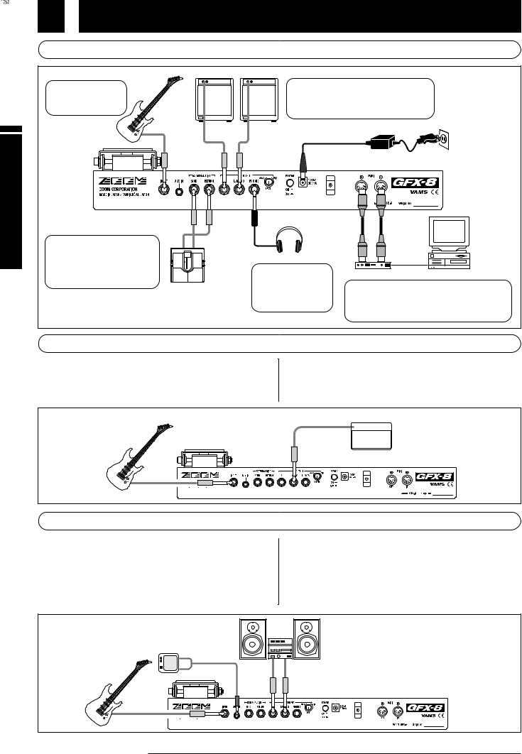
 Connection Example (1) Instrument/amplifier connection
Guitar amplifier
Use a mono cable to connect the guitar to the INPUT jack.
Guitar
Use a mono cable to connect the OUTPUT L/MONO jack only (for a monaural setup) or the OUTPUT L/MONO jack and OUTPUT R jack to the guitar amplifier or playback system.
INPUT |
|
OUTPUT |
AC adapter |
R |
L/MONO |
|
EXTERNAL DIST |
EXTERNAL |
|
|
SEND |
DIST |
|
|
RETURN |
When using the GFX-8 together |
IN |
OUT |
with a distortion device or other |
|
|
effect, connect the device |
|
|
between the EXT.DIST SEND |
|
|
jack and EXT.DIST RETURN |
|
|
jack. |
|
|
Guitar effect
*The on/off condition and signal output level of a compact effect connected to the EXT.DIST SEND jack/EXT.DIST RETURN jack can be stored as part of a patch (see page 20).
PHONES |
MIDI OUT |
MIDI IN |
|
Headphone |
MIDI IN |
MIDI |
|
OUT |
|||
To monitor the sound |
|
|
Computer |
|
MIDI interface |
||
with a pair of |
|
||
|
|
|
|
headphones, connect the |
When using the supplied software to edit the patches |
||
cable to the OUTPUT |
|
of the GFX-8 on a computer, connect the MIDI |
|
PHONES jack. |
|
interface of the computer to the MIDI IN/OUT jacks of |
|
|
|
the GFX-8, using MIDI cables. |
|
 Connection Example (2) Connection to power amp input jack of guitar amplifier
If your guitar amplifier is equipped with a power amplifier input |
* When using the GFX-8 in this way, it is recommended to activate |
jack, you can directly connect the OUTPUT L/MONO jack of the |
the built-in amp simulator (see page 7). |
GFX-8 to the power amp input jack, using the GFX-8 as a guitar |
|
preamplifier.
POWER AMP.INPUT
 Guitar amplifier
OUTPUT
L/MONO
Guitar INPUT
 Connection Example (3) CD player/MD player connection
A component with stereo line level output such as a CD player or MD |
* Using the sampler function of the GFX-8, it is also |
player can be connected to the AUX IN jack, using a stereo Y |
possible to record the signal supplied to the AUX IN jack |
cable. The signal supplied to this jack is not processed by the |
(see page 34). |
effects of the GFX-8 and is sent directly to the OUTPUT jacks. |
* When using hi-fi equipment (mixer, audio system or |
This allows you for example to listen to a CD while practicing a guitar |
similar) instead of a guitar amplifier, activating the built-in amp |
phrase. |
simulator (see page 7) is recommended. |
CD player
Playback system
AUX |
OUTPUT |
IN R |
L/MONO |
Guitar INPUT
6 ZOOM GFX-8
Preparations
This section explains the steps you should take before playing sound through the GFX-8.
 Power Up
1.Verify that the AC adapter, instrument, and amplifier/playback system are correctly connected to the GFX-8.
Before making any connections, be sure to turn power to all components off. Also, you should turn the volume on the amplifier or playback system to minimum, and set the
OUTPUT LEVEL knob on the rear panel of the GFX-8 to the 12
o'clock position.
2.Turn the system on in the order GFX-8  amplifier.
3.While playing your instrument, adjust the volume control on the amplifier, the level control of the instrument, and the OUTPUT LEVEL knob of the GFX-8 to a suitable position.
 Setting up the Amp Simulator
The GFX-8 incorporates an amp simulator that can duplicate the electrical characteristics and cabinet sound of various guitar amplifiers. Before starting to use the GFX- 8, we recommend that you set up the amp simulator so that it matches the connection type of the playback system or guitar amplifier. This will assure that you get optimum results from the GFX-8.
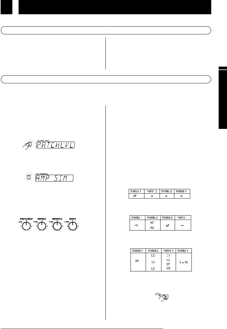
1.Immediately after turning on the GFX-8, press the TOTAL key.
The GFX-8 switches to the edit mode which allows you to change various internal settings. The TOTAL key flashes red, and the display shows "PATCHLVL".
2.Press the TOTAL key twice, so that it flashes orange.
The display indication changes to "AMP SIM".
3.Use the PARM knobs 1 - 4 to select the amp simulator setting that matches the playback system.
While the TOTAL key is flashing orange, the PARM knobs 1 - 4 serve to set the amp simulator operation.
|
|
|
|
|
|
|
|
|
|
|
|
|
|
|
|
|
|
|
|
|
|
|
|
|
|
|
|
(1) PARM knob 1 |
|
(3) PARM knob 3 |
|
||||||||||
|
|
|
|
(2) PARM knob 2 |
(4) PARM knob 4 |
||||||||
(1) PARM knob 1 |
|
AMP SIM |
|
|
|
|
|||||||
Switches amp simulator ON/OFF. |
|
|
|
|
|||||||||
(2) PARM knob 2 |
|
AMP TYPE |
|
|
|
|
|||||||
Selects the amp simulator characteristics as follows (only if parameter 1 is set to "on".
 Line connection
|
•LC |
General combo type amplifier |
|
•Lb |
Bright combo type amplifier |
|
•LS |
Stack type amplifier |
|
Power amplifier connection |
|
|
||
|
•AC |
Combo type amplifier |
|
•AS |
Stack type amplifier |
(3) PARM knob 3 |
CABINET |
|
Selects the speaker cabinet simulator type. |
||
•oF |
Cabinet simulator OFF |
|
•C1 |
Combo amplifier cabinet with one 12" speaker |
|
•C2 |
Combo amplifier cabinet with two 12" speakers |
|
•ST |
Stack amplifier with four 10" speakers |
|
•WL |
Stack amplifier tower with four 10" speakers |
|
(4) PARM knob 4 |
CABI DPT |
|
Adjusts the depth of the cabinet simulator effect, in the range from 0 - 10.
Recommended settings for various connection methods and playback systems are as follows.
 Connected to guitar amplifier input jack
 Connected to power amplifier input jack of guitar amplifier
 Connected to hi-fi playback system such as mixer or audio system
4.When the settings are complete, press the STORE key twice.
T`he new amp simulator setting is stored. This setting is retained also when power to the unit is turned off.
ZOOM GFX-8 |
7 |
Preparations
Unit) the Out (Trying Guide Quick
Quick Guide (Trying Out the Unit)
The Quick Guide explains the basic steps for using the GFX-8 in play mode. This lets you use the unit right away, to check out
what it can do.
Selecting the patch/bank number/group
In play mode, the name of the currently selected patch is shown on the display.
The group and bank number of the patch can be checked on the GROUP/BANK indicator.
Patch name |
Group Bank number |
 To switch the patch within the same bank, press one of the foot switches 1 - 4 whose LED is not lit.
 To switch to a patch from another bank number or group, use the BANK UP/DOWN foot switches and the foot switches 1 - 4 to select the bank number and group.
• For details on patch/bank/group switching, refer to p. 10.
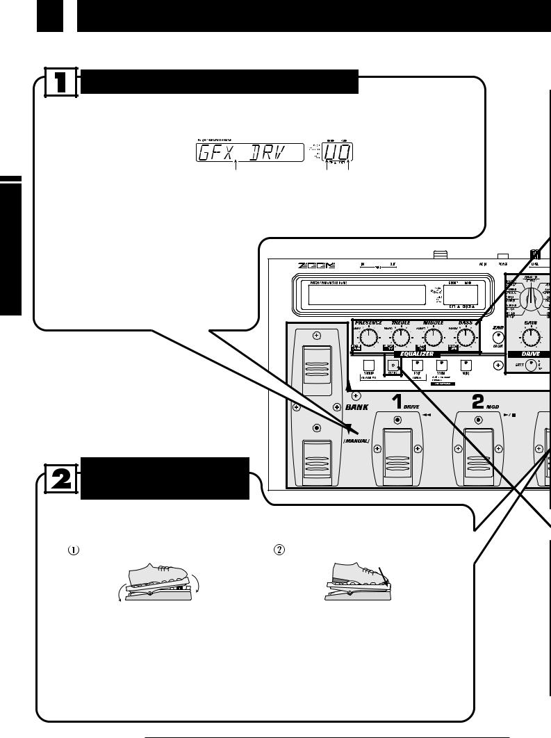
To alter the effect with
RTM
RTM (real-time modulation) refers to changing an effect with the expression pedal in real time.
Rock the expression pedal back and |
Push the expression pedal fully down. |
forth. |
|
Move back and forth |
Push fully down |
The effect changes as the expression pedal is moved. The parameter that is controlled can be programmed for each patch. Try out this function to see which parameter changes for the stored patches.
The expression pedal incorporates a switch that operates when the pedal is pushed firmly down. The switch turns the module for which RTM control is possible on and off.
•For information on effects that allow RTM control, see p. 30.
•For more information on the use of the expression pedal, see p. 41.
8 ZOOM GFX-8
Quick Guide (Trying Out the Unit)
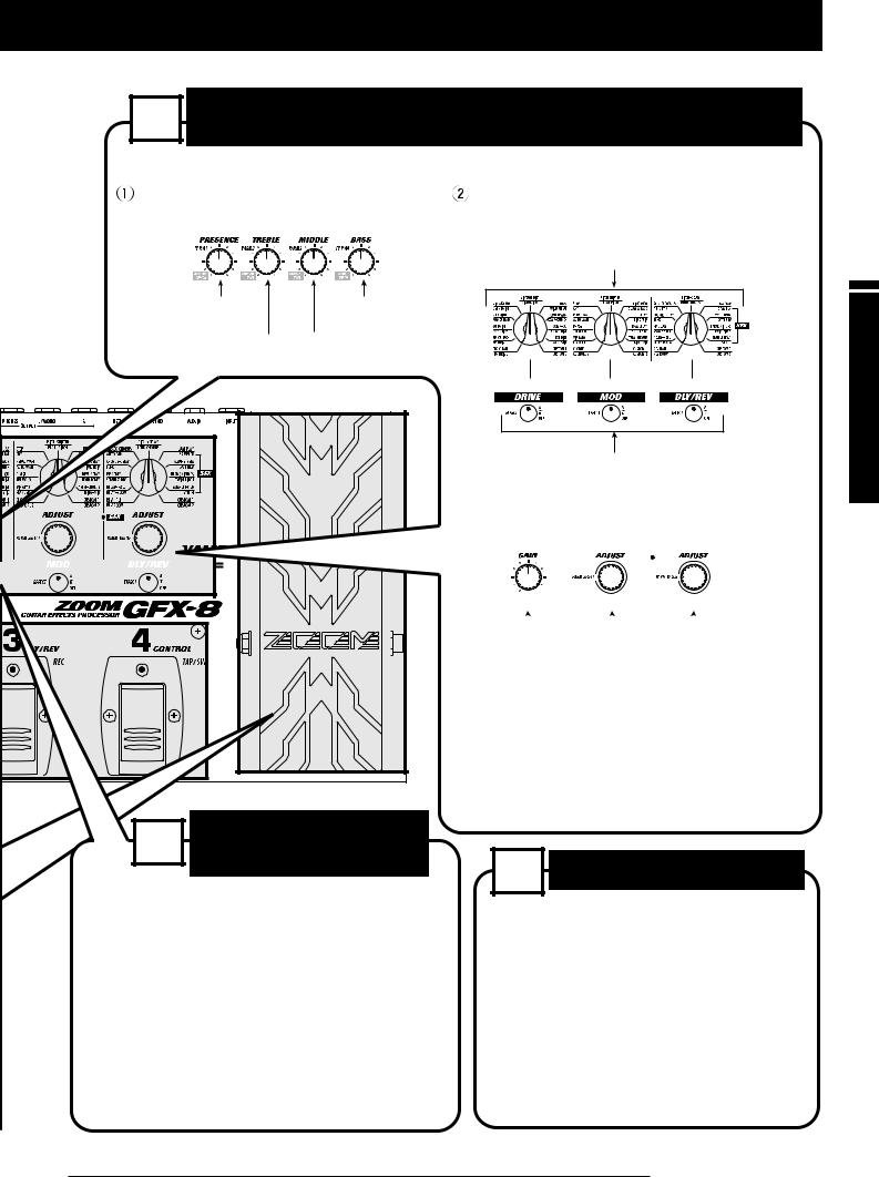
To select other effects or adjust the effect intensity, use 3 the easy edit function.
The steps listed below will result in a change of the patch sound quality and effect intensity.
To adjust the patch sound quality, |
To change the effect, use the DRIVE, |
|
operate PARM knobs 1 - 4. |
MOD, DLY/REV selectors and keys. |
|
|
|
Turn the selector to choose the desired effect in the respective |
|
|
module (DRIVE, MOD, DLY/REV). |
Adjusts the ultra-high |
Adjusts the low |
|
frequency range. |
frequency range. |
|
Adjusts the high |
Adjusts the medium |
|
frequency range. |
frequency range. |
|
Switches the respective module (DRIVE, MOD, DLY/REV)
ON and OFF and switches the group for selectable effects.
 To change the effect intensity, operate the
GAIN, PARM SELECT, or PARM VALUE knob.
|
|
|
|
|
|
|
|
|
|
|
|
|
|
|
|
|
|
|
|
|
|
|
|
|
|
|
|
|
|
|
|
|
|
|
|
|
|
|
|
|
|
|
|
|
|
|
|
|
|
|
|
|
|
|
|
|
|
|
|
|
|
|
|
|
|
|
|
|
|
|
|
|
|
|
|
|
|
|
|
|
|
|
|
|
|
|
|
|
|
|
|
|
|
|
|
|
|
|
|
|
|
|
|
|
|
|
|
|
|
|
|
|
|
|
|
|
|
|
|
|
|
|
|
|
|
|
|
|
|
|
|
|
|
|
|
|
|
|
|
|
|
|
|
|
|
|
|
|
|
|
|
|
|
|
|
|
|
|
|
|
|
|
|
|
|
|
|
|
|
|
|
|
|
|
Adjusts a major parameter |
|
|
Adjusts a major parameter |
|||||||||||||
|
|
|
|
|
|
|
of the DRIVE module. |
|
|
of the DLY/REV module. |
|||||||||||||
|
|
|
|
|
|
|
|
|
|
|
|
|
|
|
|
|
|
|
|
|
|
|
|
Adjusts a major parameter of the MOD module.
* During adjustment, the key for that module flashes.
* The parameter that can be adjusted differs for each patch.
• For more information on easy edit, see p. 11.
• For more information on full edit, see p. 14.
4 Topatchstore an adjusted
To store an edited patch, press the STORE key twice.
If required, change the store target with the BANK UP/DOWN foot switches and foot switches 1 - 4 before pressing the STORE key twice. Note that only patches in a user group can be selected as store targets.
If you press the CANCEL key before pressing the STORE key twice, the store procedure is aborted and the unit returns to the play mode.
• For more information on storing patches, see p. 18.
5 Other useful functions
•For information on using the amp simulator, see p. 7.
•For information on using the built-in tuner, see p. 12.
•For information on record/playback of phrases (sampler), see p. 34.
•For information on special playback of recorded phrases (jam play), see p. 32.
Unit) the Out (Trying Guide Quick
ZOOM GFX-8 |
9 |
Operation) Mode (Play Patches to Listening
Listening to Patches (Play Mode Operation)
Selecting and playing patches stored in the memory of the GFX-8 is called "play mode". The GFX-8 is always in this mode immediately after being turned on. This section describes how to use the functions available in this mode.
 Panel Indication in Play Mode
In play mode, the following information is shown on the panel.
(2) Group (U, u, A, b, C, d)
U and u are user groups,
A - d are preset groups.
(3) Bank number (0 - 9)
(1) Patch name
(5)The foot switch LED
of the currently  selected patch
  lights up.
(4)When a dot (.) is shown here, the user group/preset group patches can be selected continuously.
(6)Lights up in red if the EQ module in the patch is ON.
(7)When the LED is red, the effect is from group A, and when it is green, it is from group B.
When the LED is out, the effect is off.
 Selecting a Patch
1.To switch patches in play mode, press a foot switch 1 - 4 whose LED is not lit.
In play mode, foot switches 1 - 4 serve to select a patch from the same group/bank. The LED of the currently selected foot switch is lit.
2To select a patch from a different group/bank, press the BANK UP or DOWN foot switch to switch the group/patch, and then use the foot switches 1 - 4 to select the new patch.
For example, when the BANK UP foot switch is pressed repeatedly, the group/bank number changes as follows.
User group
Preset group
The patch is not switched as long as you only switch the bank/group (changed section of GROUP/BANK indicator
10 ZOOM GFX-8
flashes). It is switched only after you press one of the foot
switches 1 - 4 (the flashing of the GROUP/BANK indicator
stops).
If desired, you can limit the action of the BANK UP/DOWN
HINT
foot switches to select only user group banks, or only preset group banks. To do this, press the GROUP key. With each push of this key, the selectable groups are cycled as follows.
Both |
User group |
Preset group |
Both |
||||
groups |
|
only |
|
only |
groups |
||
|
|
|
|
|
|
|
|
 Using the Easy Edit Function
To edit patches of the GFX-8, the user normally will activate the edit mode, select the desired parameter, and change the setting. However, it is also possible to switch effects in modules and change major effect parameters in play mode. This is called the easy edit function.
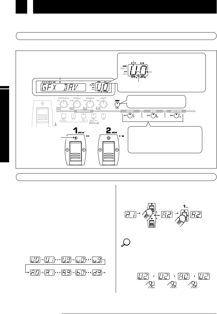
1.To switch the effect used in the DRIVE, MOD, or DLY/REV module, operate the selector and key for the respective module.
Select DRIVE module effect.
Select MOD module effect.
Select DLY/REV module effect.
Switches the respective module (DRIVE, MOD, DLY/REV) ON and OFF and switches the group for selectable effects. With each push of the key, the unit cycles through the following three states.
Key out or slowly flashing red
Respective module is OFF.
Key lit/flashing red
Module is ON and effect from group A (upper labels) is selected.
Key lit/flashing green
Module is ON and effect from group B (lower labels) is selected.
When the effect is switched, the name of the new effect is shown on the display for about 2 seconds. The EDITED mark (.) in the GROUP/BANK indicator lights up. This indicates that an effect parameter of this patch has been edited. The mark disappears when the setting is changed back to the original setting.
 EDITED mark (.)
While only the effect group was switched, the previous
NOTE effect is still active. The change does not occur until the selector for the respective module is operated. Therefore the selector position and the actual effect may differ during this interval.
2.To adjust a major parameter of each module, operate the following knobs.
[EQ]
PRESENCE:
Adjusts boost/cut in the ultra-high frequency range.
TREBLE:
Adjusts boost/cut in the high frequency range.
MIDDLE:
Adjusts boost/cut in the medium frequency range.
BASS:
Adjusts boost/cut in the low frequency range.
[PARM knobs 1 - 4]
Adjust the following EQ module parameters.
[GAIN knob]
Adjusts a major parameter of the DRIVE module. In almost all patches, this is the GAIN parameter that determines the distortion intensity.
[PARM SELECT/ADJUST knob]
Adjusts a major parameter of the MOD module.
[PARM VALUE/ADJUST knob]
Adjusts a major parameter of the DLY/REV module.
When one of the above knobs is moved, the display shows the parameter name and the GROUP/BANK indicator shows the parameter value for about 2 seconds.
Parameter name |
Setting value |
Which parameter is assigned to the GAIN knob, PARM SELECT/ADJUST knob, and PARM VALUE/ADJUST knob depends on which effect is selected for that module (see page 19 - 29).
• Trying to change effects or parameters which are set to
NOTE
OFF in the current module has no effect. In this case, the indication "OFF" is shown on the display.
•All changes made with the easy edit function are temporary. Settings revert to the original condition when the patch is switched. When wishing to keep the changes, you must store the patch (see page 18).
Operation) Mode (Play Patches to Listening
ZOOM GFX-8 11
Operation) Mode (Play Patches to Listening
 Using the Bypass (Mute)/Tuner Function
The GFX-8 incorporates an auto-chromatic tuner for guitars. To use the tuner function, the built-in effects must be bypassed (temporarily turned off) or muted (original sound and effect sound turned off).
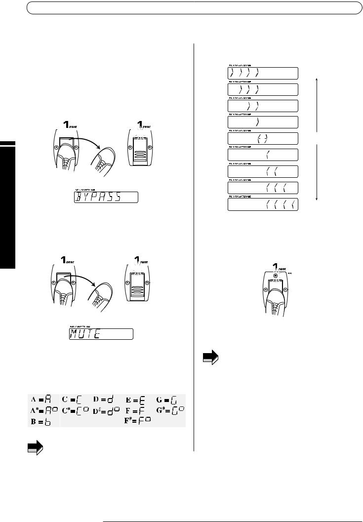
1.To set the GFX-8 to the bypass (mute) condition, press and immediately release the foot switch 1 - 4 that has selected the currently active patch (the foot switch whose LED is lit).
In play mode, when you quickly press the foot switch whose LED is lit, the GFX-8 switches to the bypass condition. The foot switch LED now flashes and the indication "BYPASS" is shown on the display.
Lit 


 Flashes
Release immediately
If you press a foot switch with lit LED for longer than 1 second and then release it, the GFX-8 switches to the mute condition. The foot switch LED now flashes and the indication "MUTE" is shown on the display.
Lit 


 Flashes
Release after more than 1 second
2.Play the open string you want to tune, and watch the GROUP/BANK indicator. The GFX-8 automatically detects the pitch and the GROUP/BANK indicator shows the note which is closest to the current pitch.
3.When the GROUP/BANK indicator shows the desired note, perform fine tuning while watching the display.
Pitch is low
Pitch is correct
Pitch is high
4.Tune the other strings in the same way.
5.When tuning is completed, press the foot switch whose LED is flashing once more.
The GFX-8 returns to the play mode.
If desired, you can change the setting of the unit so that NOTE pressing the foot switch whose LED is lit will not activate
the bypass/mute condition. For details, please refer to page 41.
For tuning, always play a single note. If you play a chord,
NOTE
the pitch will not be detected correctly.
12 ZOOM GFX-8

 Adjusting the Reference Pitch of the Tuner
After the GFX-8 is turned on, the tuner reference pitch is always "center A = 440 Hz". If desired, you can change the reference pitch. This is useful for example to match your instrument to another instrument or sound source whose pitch cannot be changed easily, such as an acoustic piano or a CD. To do this, first change the reference pitch of the GFX-8 and then use to to perform tuning of your guitar.
1.In play mode, press the foot switch 1 - 4 whose LED is lit, to set the GFX-8 to the bypass/mute condition.
2.Rotate the DLY/REV (PARM VALUE) knob to adjust the reference pitch. When this knob is operated, the current reference pitch is shown on the display. The initial setting is "440" (center A = 440 Hz).
Reference pitch value
The available setting range is "435" (center A = 435 Hz) - "445"
(center A = 445 Hz) in 1-Hz steps.
3.When tuning is completed, once more press the foot switch whose LED is flashing.
The GFX-8 returns to the play mode.
When the GFX-8 is turned off and on again, the reference
NOTE |
pitch will be reset to "440". |
|
 Switching Modules On and Off During Play (Manual Mode)
The condition where foot switches 1 - 4 can be used to switch the modules in a patch ON and OFF individually and where specific parameters can be adjusted is called "manual mode". In manual mode, the modules in a patch can be used like independent compact effects.
1. In play mode, select a patch.
2. Press the BANK DOWN foot switch and hold it down for at least 1 second.
The GFX-8 switches to the manual mode. The display shows
"MANUAL".
Hold down for
at least 1 second
3.Operate foot switches 1 - 4.
In manual mode, foot switches 1 - 4 have the following functions.
The parameter to be controlled by foot switch 4
NOTE |
(CONTROL switch) is set using the TOTAL module (see |
|
page 29).
4.To return to the play mode, press the BANK DOWN foot switch once more.
Operation) Mode (Play Patches to Listening
ZOOM GFX-8 13
Changing the Sound of a Patch (Edit Mode)
Mode) (Edit Patch a of Sound the Changing
The condition where you can change the parameters that make up a patch to create your own sound is called "edit mode". This section describes how to use edit mode.
 Basic Edit Mode Steps
The basic steps that are normally taken in edit mode are explained here. Besides these, the edit mode also provides a short cut to quickly edit a specific parameter (see page 16).
1.In play mode, select the patch you want to edit.
The patch can be from a user group or preset group. However, because patches in the preset groups are read-only, after you have edited a patch, you can only select a user group patch as store target.
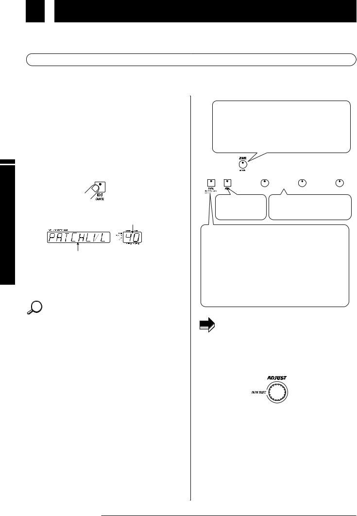
2.Press the EDIT key.
The EDIT key LED lights up, and the GFX-8 enters the edit mode.
In edit mode, the following information is shown on the panel.
Currently selected parameter value
Currently selected parameter name
The keys and foot switch LEDs of modules that are ON in the current patch are lit.
The key of the module selected for editing flashes.
When edit mode was activated immediately after switching
HINT patches, the TOTAL key flashes. When edit mode was activated after easy edit, the key of the edited module flashes.
3.Use the panel keys to select the module you want to edit.
In edit mode, the following keys serve to select the module for editing. The selected key flashes.
ZNR/EQ EDIT key
Selects the EQ module or ZNR.
With each push of the key, the color of the flashing LED changes, and the edit target changes as follows.
|
Flashing red |
EQ module page 1 |
|
|
||||||
|
Flashing green |
EQ module page 2 |
|
|
||||||
|
Flashing orange |
ZNR |
|
|
||||||
|
|
|
|
|
|
|
|
|
|
|
|
|
|
|
|
|
|
|
|
|
|
|
|
|
|
|
|
|
|
|
|
|
|
|
|
|
|
|
|
|
|
|
|
|
|
|
|
|
|
|
|
|
|
|
|
|
|
|
|
|
|
|
|
|
|
MIDI key |
DRIVE, MOD, DLY/REV key |
|
Make MIDI settings |
||
Select the DRIVE, MOD, or |
||
(see page 35). |
DLY/REV module respectively. |
TOTAL key
Serves to set the patch name and patch level (overall output level of the patch) and other parameters applying to the entire patch, as well as global parameters that apply to all patches. With each push of the key, the color of the flashing LED changes, and the edit target changes as follows.
Flashing red |
Set patch name and patch level . |
Flashing green |
Set RTM and CONTROL switch |
|
functions (see page 30). |
Flashing orange |
Make amp simulator (global |
|
parameter) settings . |
If a module is selected that is set to OFF in the current
NOTE patch, editing is not possible (display shows "OFF"). However, ZNR settings can be made also when the EQ module is OFF.
4.Use the PARM SELECT knob to select the parameter you want to edit.
When you turn the PARM SELECT knob, the effects of the
module selected in step 3 and the effect parameters are shown in turn on the display. (Which parameter is shown depends on the currently selected module and effect). The currently selected parameter setting can be checked using the GROUP/BANK indicator.
14 ZOOM GFX-8
 Loading...