


Contents
Safety Precautions • • • |
• |
• • • |
• • • • |
• • |
• • • • • • |
• • |
• • • • • |
• |
• |
• • |
• • • • • |
• |
• • • • • • • • • • |
• • • • • • • • • • • • • • • • • • • • • • • • • • • • • • • • • • • • • • • • • • • • • • • |
• |
2 |
||||||||||
Usage Precautions• • • • |
• |
• • • |
• • • • |
• • |
• • • • • • |
• • |
• • • • • |
• |
• • • • • • • • • |
• • • • • • • • • • |
• • • • • • • • • • • • • • • • • • • • • • • • • • • • • • • • • • • • • • • • • • • • • • • |
• |
2 |
|||||||||||||
Getting Familiar With Some Basic Terms • • |
• • |
• • • • • • • • • • |
• • • • • • • • • • • • • • • • • • • • • • • |
• • • • • • • • • • • • • • • • • • • • • • • • |
• |
|
3 |
|||||||||||||||||||
Names and Functions of Controls and Connectors • • |
• • • • • • • • • • • • • • • • • • • • • • • |
• • • • • • • • • • • • • • • • • • • • • • • • |
• |
|
4 |
|||||||||||||||||||||
Front Panel • |
• • |
• • • • • • • • |
|
• • |
• • • • |
• |
• • • |
• • • |
• |
• • |
• • • • • |
• |
• • |
• • • • • |
• • |
• |
• • • • • • • • • |
• • • • • • • • • • • • • • • • • • • • • • • |
• • • • • • • • • • • • • • • • • • • • • • • • |
• |
|
4 |
||||
Rear Panel • • |
• • |
• • • • • • • • |
|
• • |
• • • • |
• |
• • • |
• • • |
• |
• • |
• • • • • |
• |
• • |
• • • • • |
• • |
• |
• • • • • • • • • |
• • • • • • • • • • • • • • • • • • • • • • • |
• • • • • • • • • • • • • • • • • • • • • • • • |
• |
|
5 |
||||
Connection Examples • |
|
• • |
• • • • |
• |
• • • • • • • |
• • |
• • • • • |
• |
• • • • • • • • • |
• • • • • • • • • • |
• • • • • • • • • • • • • • • • • • • • • • • • • • • • • • • • • • • • • • • • • • • • • • • • |
|
6 |
|||||||||||||
Connection to one guitar amplifier (Example 1) • • • • • • • • • • • • • • • • • • • • • • • • • • • • • • • • • • • • • • • • • • • • • • • • • • • • • • • • • • |
|
6 |
||||||||||||||||||||||||
Connection to two guitar amplifiers (Example 2) • • • • • • • • • • • • • • • • • • • • • • • • • • • • • • • • |
• • • • • • • • • • • • • • • • • • • • • • • • |
• |
|
6 |
||||||||||||||||||||||
Connection to Head phone (Example 3) • • |
• • |
• • • |
• • • |
• • • • • • • • • • • • • • • • • • • • • • • • • • • • • • • • |
• • • • • • • • • • • • • • • • • • • • • • • • |
• |
|
6 |
||||||||||||||||||
Playing a Patch (Use of the Play Mode) • |
• • • |
• • • |
• • • • • • • • • • • • • • • • • • • • • • • • • • • • • • • • |
• • • • • • • • • • • • • • • • • • • • • • • • • |
|
7 |
||||||||||||||||||||
Panel display in Play mode • • • • • • • • • • • • • • • • • • • • • • • • • • • • • • • • • • • • • • • • • • • • • • • • • • • • • • • • • • • • • • • • • • • • • • • • • • • • • • • • • |
|
7 |
||||||||||||||||||||||||
Selecting a patch • • • • |
|
• • • • • • |
• |
• • • • • • • • • • • • • • • |
• • • • • • • • • • |
• • • • • • • • • • • • • • • • • • • • • • • • • • • • • • • • |
• • • • • • • • • • • • • • • • • • • • • • • • • |
|
7 |
|||||||||||||||||
Useful functions in the Play mode • • • • • • • • • • • • • • • • • • • • • • • • • • • • • • • • • • • • • • • • • • • • • • • • • • • • • • • • • • • • • • • • • • • • • • • • • |
|
8 |
||||||||||||||||||||||||
Editing a Patch (Use of the Edit Mode) • • • • • • • |
• |
• • • • • • • • • • |
• • • • • • • • • • • • • • • • • • • • • • • • • • • • • • • • • • • • • • • • • • • • • • • |
|
|
10 |
||||||||||||||||||||
Entering the Edit mode • • • • • • • • • • • • • • • • • • • |
• • • • • • • • • • |
• • • • • • • • • • |
• • • • • • • • • • • • • • • • • • • • • • • • • • • • • • • • • • • • • • • • • • • • • • • |
|
|
10 |
||||||||||||||||||||
Panel display in Edit mode • |
• • • • • • |
• • |
• • • • • |
• |
• • • • • • • • |
• |
• • • • • • • • • • • • • • • • • • • • • • • • • • • • • • • • • • • • • • • • • • • • • • • • • • • • • • • • • |
|
|
10 |
||||||||||||||||
Editing a patch |
• • • • • |
• |
• • • |
• • • • |
• |
• • • • • • • |
• • |
• • • • • |
• |
• • • |
• • • • • |
• |
• • • • • • • • • • |
• • • • • • • • • • • • • • • • • • • • • • • • • • • • • • • • • • • • • • • • • • • • • • • |
|
|
11 |
|||||||||
Turning effect modules on and off • |
• • • • • |
• |
• • • • • • • • • |
• • • • • • • • • • |
• • • • • • • • • • • • • • • • • • • • • • • • • • • • • • • • • • • • • • • • • • • • • • • |
|
|
12 |
||||||||||||||||||
Compare • • • • • • • • • • • • • • • • • • • • • • • • • • • • • • • • • • • |
• • • • • • • • • • |
• • • • • • • • • • |
• • • • • • • • • • • • • • • • • • • • • • • • • • • • • • • • • • • • • • • • • • • • • • • |
|
|
12 |
||||||||||||||||||||
Storing a patch • • • • • |
• • |
• • |
• • • • |
• |
• • • • • • • |
• • |
• • • • • |
• |
• • • • • • • • |
• |
• • • • • • • • • • |
• • • • • • • • • • • • • • • • • • • • • • • • • • • • • • • • • • • • • • • • • • • • • • • |
|
|
12 |
|||||||||||
Effect Types and Parameters • • • • • |
• • |
• • • • • |
• |
• • • • • • • • |
• |
• • • • • • • • • • |
• • • • • • • • • • • • • • • • • • • • • • • • • • • • • • • • • • • • • • • • • • • • • • • |
|
|
13 |
||||||||||||||||
Effect Module 1: (PRE) • |
• • • • • • |
• • |
• • • • • |
• |
• • • • • • • • • |
• • • • • • • • • • |
• • • • • • • • • • • • • • • • • • • • • • • • • • • • • • • • • • • • • • • • • • • • • • • |
|
|
13 |
||||||||||||||||
Effect Module 2: Equalizer (EQ) • • • • |
• • • • • • • • • • |
• • • • • • • • • • • • • • • • • • • • • • • • • • • • • • • • • • • • • • • • • • • • • • • • • • • • • • • • • |
|
|
15 |
|||||||||||||||||||||
Effect Module 3: Modulation |
|
• • |
• • • • • |
• |
• • • • • • • • |
• |
• • • • • • • • • • • • • • • • • • • • • • • • • • • • • • • • • • • • • • • • • • • • • • • • • • • • • • • • • |
|
|
16 |
||||||||||||||||
Effect Module 4: Delay • • • • • • • • • • • • • • • |
• |
• • • • • • • • |
• |
• • • • • • • • • • |
• • • • • • • • • • • • • • • • • • • • • • • • • • • • • • • • • • • • • • • • • • • • • • • |
|
|
20 |
||||||||||||||||||
Effect Module 5: Reverb (REV) • • • • |
• |
• • • • • • • • |
• |
• • • • • • • • • • • • • • • • • • • • • • • • • • • • • • • • • • • • • • • • • • • • • • • • • • • • • • • • • |
|
|
20 |
|||||||||||||||||||
Patch level • • • • • • |
• • |
• • |
• • • • |
• |
• • • • • • • |
• • |
• • • • • |
• |
• • • • • • • • |
• |
• • • • • • • • • • |
• • • • • • • • • • • • • • • • • • • • • • • • • • • • • • • • • • • • • • • • • • • • • • • |
|
|
21 |
|||||||||||
About the TOTAL parameters |
• • • |
• • |
• • • • • |
• |
• • • • • • • • |
• |
• • • • • • • • • • • • • • • • • • • • • • • • • • • • • • • • • • • • • • • • • • • • • • • • • • • • • • • • • |
|
|
21 |
||||||||||||||||
EXTERNAL LOOP • • • |
• |
• • • • • • • |
• • |
• • • • • |
• |
• • • • • • • • • |
• • • • • • • • • • |
• • • • • • • • • • • • • • • • • • • • • • • • • • • • • • • • • • • • • • • • • • • • • • • |
|
|
21 |
|||||||||||||||
EXTERNAL CTRL OUT (External Control) • • • • • • • • • |
• • • • • • • • • • • • • • • • • • • • • • • • • • • • • • • • • • • • • • • • • • • • • • • |
|
|
21 |
||||||||||||||||||||||
MINIMUM VOLUME • |
• • • • • • • |
• • |
• • • • • |
• |
• • • • • • • • • |
• • • • • • • • • • |
• • • • • • • • • • • • • • • • • • • • • • • • • • • • • • • • • • • • • • • • • • • • • • • |
|
|
22 |
||||||||||||||||
MIDI CH (MIDI Channel) • • • • • • • • • • • |
• • • • • • • • • • |
• • • • • • • • • • |
• • • • • • • • • • • • • • • • • • • • • • • • • • • • • • • • • • • • • • • • • • • • • • • |
|
|
22 |
||||||||||||||||||||
EXP. SELECT (Expression Select) • |
• |
• • • • • • • • |
• |
• • • • • • • • • • |
• • • • • • • • • • • • • • • • • • • • • • • • • • • • • • • • • • • • • • • • • • • • • • • |
|
|
22 |
||||||||||||||||||
Edit Mode Application Examples • |
• • • • • |
• |
• • • • • • • |
• • |
• • • • • • • • • • |
• • • • • • • • • • • • • • • • • • • • • • • • • • • • • • • • • • • • • • • • • • • • • • • |
|
|
23 |
|||||||||||||||||
Tapping input of delay time |
|
• • • • • • |
• • |
• • • • • |
• |
• • • • • • • • |
• |
• • • • • • • • • • • • • • • • • • • • • • • • • • • • • • • • • • • • • • • • • • • • • • • • • • • • • • • • • |
|
|
23 |
|||||||||||||||
External effecter loop |
• |
• • • • |
• |
• |
• • |
• • • |
• |
• • |
• • • • • |
• |
• • • • • • • |
• • |
• • • • • • • • • • |
• • • • • • • • • • • • • • • • • • • • • • • |
• • • • • • • • • • • • • • • • • • • • • • • • |
|
|
23 |
||||||||
External control • • • • |
• • |
• • |
• • • • |
• |
• • • • • • • |
• • |
• • • • • |
• |
• • • • • • • • • |
• • • • • • • • • • |
• • • • • • • • • • • • • • • • • • • • • • • • • • • • • • • • • • • • • • • • • • • • • • • |
|
|
23 |
||||||||||||
Expression pedal control • • • • • • • • • • • • • • • • • • • • • • • • • • • • • • • • • • • • • • • • • • • • • • • • • • • • • • • • • • • • • • • • • • • • • • • • • • • • • • • • • • • • |
|
|
24 |
|||||||||||||||||||||||
Other Functions • • |
• • • • • • |
• • |
• • |
• • • • |
• |
• • • • • • • |
• • |
• • • • • |
• |
• • • • • • • • • |
• • • • • • • • • • |
• • • • • • • • • • • • • • • • • • • • • • • • • • • • • • • • • • • • • • • • • • • • • • • |
|
|
25 |
|||||||||||
Restoring individual factory preset patches (patch recall) • • • • • • • • • • • • • • • • • • • • • • |
• • • • • • • • • • • • • • • • • • • • • • • • |
|
|
25 |
||||||||||||||||||||||
Restoring all factory preset patches (initialize) • • • • • • • • • • • • • • • • • • • • • • • • • • • • • • • • • • • • • • • • • • • • • • • • • • • • • • • • • • |
|
|
25 |
|||||||||||||||||||||||
Volume pedal control • • • • • • • • • • • • • • • • • • • • • • • • • • • • • • |
• • • • • • • • • • |
• • • • • • • • • • • • • • • • • • • • • • • |
• • • • • • • • • • • • • • • • • • • • • • • • |
|
|
25 |
||||||||||||||||||||
MIDI control • |
• • • • • • |
• • |
• • |
• • • • |
• |
• • • • • • • |
• • |
• • • • • |
• |
• • • • • • • |
• • |
• • • • • • • • • • |
• • • • • • • • • • • • • • • • • • • • • • • |
• • • • • • • • • • • • • • • • • • • • • • • • |
|
|
26 |
|||||||||
Swapping the pedal functions • • • |
• |
• • |
• • • • • |
• |
• • • • • • • • • |
• • • • • • • • • • |
• • • • • • • • • • • • • • • • • • • • • • • • • • • • • • • • • • • • • • • • • • • • • • • |
|
|
26 |
||||||||||||||||
Application Examples for Use of Foot Switch and Pedal Switch 1–4 • • • • • • • • • • • • • • • • • • • • • • • |
|
|
27 |
|||||||||||||||||||||||
Using the FS01 • • • • • |
• • |
• • |
• • • • |
• |
• |
• • • • • • |
• • |
• • • • • |
• |
• • • • • • • • |
• |
• • • • • • • • • • |
• • • • • • • • • • • • • • • • • • • • • • • • • • • • • • • • • • • • • • • • • • • • • • • |
|
|
27 |
||||||||||
Specifications• • • • • • • • • • |
• • |
• • |
• • • • |
• |
• |
• • • • • • |
• • |
• • • • • |
• |
• • • • • • • • |
• |
• • • • • • • • • • |
• • • • • • • • • • • • • • • • • • • • • • • • • • • • • • • • • • • • • • • • • • • • • • • |
|
|
28 |
||||||||||
|
|
|
|
|
|
|
|
|
|
|
|
|
|
|
|
|
|
|
|
|
|
|
|
|
|
|

Thank you for selecting the ZOOM Player Pro 4040 (hereafter simply called the “4040”).
The 4040 is a sophisticated multi-effect device with the following features and functions:
•A total of 25 built-in individual effects, which can be combined in patches of up to six effects. 40 preset patches and a user memory for 40 additional patches offer extraordinary flexibility.
•Integrated volume and expression pedals allow adjustment of output level and effect settings in real time. This is ideal for use during a live performance.
•Integrated auto-chromatic guitar tuning function lets you quickly and precisely tune instruments on stage.
•Compression and distortion effects are generated using analog circuitry, to assure rich and natural-sounding sustain and distortion.
•Send/return Jacks allow connection of external effect devices, and a control out lets you switch guitar amp channels. You can even program the use of these connectors as part of a patch, to create sophisticated sound effects.
•MIDI OUT for control of external MIDI devices makes the 4040 convenient as a system control center.
•By using the optional foot switch FS01, single effect on/off switching during a performance is possible, for further enhanced playability.
Please take the time to read this manual carefully, in order to get the most out of your 4040 and to ensure optimum performance and reliability.
1

Safety Precautions
Please observe the following safety tips and precautions to ensure hazard-free use of the 4040.
• Power requirements
The 4040 is powered by the supplied AC adapter AD0003/AD0004. To prevent malfunction and safety hazands, Do not use any other kind of AC adapter.
When using the 4040 in an area with a different line voltage, please consult your local ZOOM distributor about acquiring a proper AC adapter.
• Environment
Avoid using your 4040 in environments where it will be exposed to:
•Extreme temperature
•High humidity or moisture
•Excessive dust or sand
•Excessive vibration or shock
•Handling
Since the 4040 is a precision electronic device, avoid applying excessive force to the switches and buttons. Also take care not to drop the unit, and do not subject it to shock or excessive pressure.
• Alterations
Never open the case of the 4040 or attempt to modify the product in any way since this can result in damage to the unit.
• Connecting cables and input and output jacks
You should always turn off the power to the 4040 and all other equipment before connecting or disconnecting any cables. Also make sure to disconnect all cables and the AC adapter before moving the 4040.
Usage Precautions
• Electrical interference
The 4040 uses digital circuitry that may cause interference and noise if placed too close to other electrical equipment, such as TV sets and radio receivers. If such problems occur, move the 4040 further away from the affected equipment. Also, when fluorescent lights or devices with built-in motors are close to the 4040, the unit may not function properly.
• Cleaning
Use a soft, dry cloth to clean the 4040. If necessary, slightly moisten the cloth. Do not use abrasive cleanser, wax, or solvents (such as paint thinner or cleaning alcohol), since these may dull the finish or damage the surface.
Please keep this manual in a convenient place for future reference.
2
Getting Familiar With Some Basic Terms
This manual has been written so that it can be easily understood by first-time users. However, the 4040 offers several special functions which are not available with a conventional effect processor. This section explains some of the terms used to describe such functions.
• Effect Module
The 4040 incorporates five types of effect groups which are referred to as “effect modules”. Each effect module can be thought of as a single compact effect. The 4040 therefore operates like five compact effects connected in series. In addition, it is also possible to connect external effect devices.
The 4040 offers the following five effect modules:
•PRE (Analog compressor and distortion effects)
•EQ (Equalizer and wah effects, amp simulation)
•MODULATION (Modulation effects for changing pitch or sound timbre, such as pedal pitch and flanger)
•DELAY (Delay effects)
•REVERB (Reverberation effects)
•Effect Type
Each effect module contains several effect variations which are called “effect types”. Each effect module can use one effect type at a time. For a list of effect types in each effect module, please see the table on page 10.
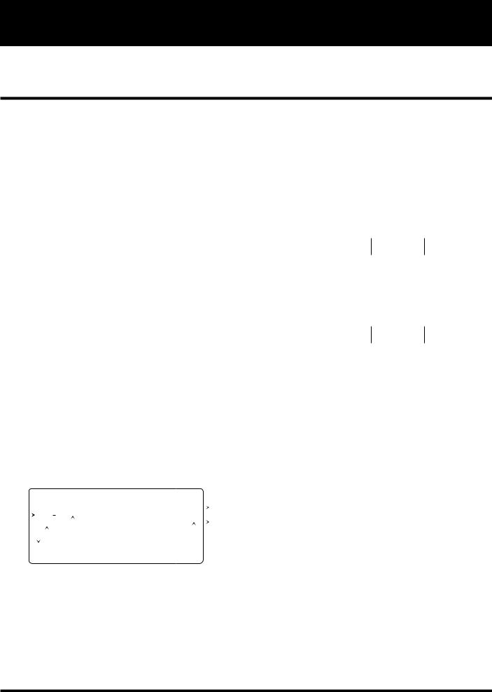
serve to switch between patches. Such a set of four patches is referred to as a “bank”. To select a patch, first specify the group and the bank number (0 – 9), and then use the foot pedal switches 1 – 4 to select the patch number.
GROUP |
BANK No. |
PATCH No. |
|
|
|
|
0 |
1 – 4 |
|
|
|
|
1 |
1 – 4 |
USER |
|
|
2 |
1 – 4 |
|
|
|
|
|
|
|
|
9 |
1 – 4 |
|
|
|
|
0 |
1 – 4 |
|
|
|
|
1 |
1 – 4 |
PRESET |
|
|
2 |
1 – 4 |
|
|
|
|
|
|
|
|
9 |
1 – 4 |
|
|
|
• Patches and Groups
The 4040 allows you to use a maximum of five effect modules simultaneously. A combination of effect modules, each with individual parameter settings plus the final output level setting is referred to as a “patch”. The patch also includes the external effect on/off setting, external control setting, and expression pedal setting.
PATCH
|
|
|
|
|
|
|
|
|
|
|
|
|
|
|
|
|
|
|
INPUT |
|
PRE |
|
EQ |
|
|
MODULATION |
|
DELAY |
|
REVERB |
|
OUTPUT |
|||||
|
|
|
|
|
||||||||||||||
|
|
|
|
|
|
|
|
|
|
|
|
|
|
|
|
|
|
|
|
|
|
|
|
|
|
|
|
|
|
|
|
|
|
|
|
|
|
|
|
|
|
|
|
|
|
|
|
|
|
|
|
|
|
|
|
|
|
|
EXT |
|
VOL. PEDAL |
|
PATCH LEVEL |
|
|
||||||||||
|
|
|
|
|
|
|
|
|
|
|
|
|
|
|
|
|
|
|
The 4040 has two memory areas or “groups” where patches are stored: the USER group for patches that can be freely altered and stored by the user, and the PRESET group for factory defined read-only patches. There are 40 patches in each group, for a total of 80 patches.
• Bank
The 4040 calls up patches in sets of four, and the foot pedals
• Parameter
The elements which determine the sound of an effect are referred to as “parameters”. Parameter values can be adjusted for each effect module, to create your own patches with the 4040.
• Mode
The functions of the 4040 can be roughly divided into three different categories. These are called “modes”, as described below.
•Play Mode
In this mode, patches can be selected and played. This is the default mode of the 4040 when power is turned on.
•Edit (Manual) Mode
In this mode, the parameters of each patch can be edited. The mode can also serve as a manual mode to switch effect modules on and off during a performance using the pedal switches 1 – 4 and the BANK ▼ pedal.
•Special Mode
Serves to return some or all patch data to the factory preset condition.
3

Names and Functions of Controls and Connectors
Front Panel
(1) |
|
|
|
|
(2) |
|
|
|
|
|
|
|
|
|
|
|
|
|
|
|
|
|
|
|
|
|
|
|
|
|
|
|
|
|
|
|
|
|
|
|
|
|
|
|
|
|
|
|
|
|
|
|
|
|
|
|
|
|
|
|
|
|
|
|
|
|
|
|
|
(3) |
||||||||
|
|
|
|
|
|
|
|
|
|
|
|
|
|
|
|
|
|
|
|
|
|
|
|
|
|
|
|
|
|
|
|
|
|
|
|
|
|
|
|
|
|
|
|
|
|
|
|
|
|
|
|
|
|
|
|
|
|
|
|
|
|
|
|
|
|
|
|
|
|
|
|
|
|
|
|
|
|
|
|
|
|
|
|
DELAY TIME |
|
|
PRE MODULE |
|
|
|
|
|
|
|
|
|
|
|
|
|
|
|
|
|
|
|
|
|
|
|
|
|
|
|
|
|
|
|
|
|
|
|
|
|
|
|
|
|
|
|
|
|
|
|
|
|
|
|
|
|
|
|
|
|
|||||||||||||
|
|
|
|
|
BANK TAP EDIT |
|
|
ADVANCE D |
GUITA R |
EFFECT S |
PROCESSOR |
|
|
|
|
|
|
|
|
|
|
|
|
|
|
|
|
|
|
|
|
|
|
|
|
|
|
|
|
|
|
|
|
|
|
|
|
|
|
|
|
|||||||||||||||||||||||||||
|
|
|
|
|
|
|
|
|
|
|
|
|
|
|
|
|
|
|
|
|
|
|
|
|
|
|
|
|
|
|
|
|
|
|
|
|
|
|
|
|
|
|
|
|
|
|
|
|
|
|
|
|
|
|
|
|
|
|
||||||||||||||||||||
|
|
|
|
|
TUNER |
EFFECT |
1 |
|
CLN I |
3 |
|
ODI |
|
|
4 |
ODII |
|
|
|
|
|
EQ |
|
|
|
|
|
|
|
|
MODULATION |
|
|
|
|
|
|
|
|
|
|
|
|
DELAY |
|
|
|
|
REVERB |
|||||||||||||||||||||||||||||
|
|
|
|
|
2 |
|
CLN II |
5 |
|
DST I |
|
|
6 |
DST II |
1 |
EQ |
|
2 |
AMP |
|
3 |
AUTO |
4 |
PDL |
1 |
PDL |
|
2 |
PIT |
3 |
|
|
FLG |
4 |
|
PHA |
5 |
TREM |
|
1 |
|
MONO |
|
|
1 |
HALL |
|
3 |
DELAY |
|
|
|
||||||||||||||||||||||||||
|
|
|
|
|
(BYPASS) |
|
|
|
|
|
|
|
|
|
|
|
|
|
|
|
|
|
|
|
|
|
|
|
|
|
|
|
|
|
|
|
|
|
|
|
|
|
|
|
|
|
|
|
|
|
|
|
|
|
|
|
|
|
|
|
|
|
|
|
|
|
|
|
|
|
|
|
|
|
|
|
|
|
|
|
|
|
|
|
|
|
|
|
|
7 |
|
LEAD |
8 |
METAL |
|
|
|
|
SIM |
|
|
WAH |
|
WAH |
|
PIT |
|
|
|
6 |
|
|
STEP |
7 |
|
SLOW |
8 |
CHO |
|
2 |
|
PPD |
|
|
2 |
ROOM |
|
|
|
|
|||||||||||||||||||||||||||
|
|
|
|
|
|
PARM 1 |
|
|
COMP |
|
|
|
|
|
|
|
|
HIGH |
|
COLOR |
|
FREQ |
FREQ |
|
|
|
|
PITCH |
|
|
|
|
|
|
|
|
|
DEPTH |
|
|
|
|
|
|
|
|
|
|
|
|
[0– 10] |
|
|
|
TIME |
|
|
TIME |
||||||||||||||||||||
|
|
|
|
|
|
|
|
|
|
[0– 4] |
|
|
|
|
|
|
|
|
[-7– +7] |
|
[1– 3] |
|
|
[1–64] |
|
|
|
|
[0– 24] |
|
|
|
|
|
|
|
|
|
|
[0–10] |
|
|
|
|
|
|
|
|
|
|
|
|
(X100mS) |
|
|
|
[1– 10] [0– 90] (X10mS) |
|
||||||||||||||||||||
|
|
|
|
|
|
|
|
|
|
|
|
|
|
|
|
|
|
|
|
|
|
|
|
|
|
|
|
|
|
|
|
|
|
|
|
|
|
|
|
|
|
|
|
|
|
|
|
|
|
|||||||||||||||||||||||||||||
|
|
|
|
|
|
PARM 2 |
|
|
TONE |
|
|
|
|
|
|
|
|
MID |
|
|
BOX |
|
|
SENS |
|
|
EXP. |
MODE |
|
SHIFT |
|
|
|
|
|
|
|
|
|
|
|
|
|
|
|
|
|
|
|
|
|
|
|
|
|
DELAY TIME( |
) |
|
|
TONE |
|
FEEDBACK |
||||||||||||||||
|
|
|
|
|
|
|
|
|
|
|
|
|
|
|
|
|
|
|
|
|
|
|
|
|
|
3 |
|
4 |
|
5 |
|
6 |
|
7 |
8 |
RATE |
|
|
|
|
[0– 99] |
|
|
|
|
|||||||||||||||||||||||||||||||||
|
|
|
|
|
|
|
|
|
|
[-7–+7] |
|
|
|
|
|
|
|
|
[-7– +7] |
|
[1– 3] |
|
[0–10] |
|
MODE |
[1–16] |
[dn, UP] |
|
|
|
|
|
|
|
|
|
|
[1–50] |
|
|
|
|
|
|
|
|
|
|
|
|
|
|
|
[-7– +7] |
|
|
[0– 10] |
|||||||||||||||||||||
|
|
|
|
|
|
|
|
|
|
|
|
|
|
|
|
|
|
|
|
|
|
|
|
|
|
|
|
|
|
|
|
|
|
|
|
|
|
|
|
|
|
|
(mS) |
|
|
|
|
|
||||||||||||||||||||||||||||||
|
|
|
|
|
|
|
|
|
|
|
|
|
|
|
|
|
|
|
|
|
|
|
|
|
|
|
|
|
|
|
|
|
(PITCH) |
|
|
|
|
|
|
|
|
|
|
|
|
|
|
|
|
|
|
|
|
|
|
|
|
|
|
|
|
|
|
|
|
|
|
|
|
|
|
|
|
|
|
|
||
|
|
|
|
|
|
PARM 3 |
|
|
|
|
|
|
|
3 |
– |
8 |
GAIN |
MIDf |
|
DEPTH |
|
|
|
0= NORM |
|
FINE |
|
3 |
|
|
4 |
5 |
|
6 |
|
PEAK |
7 |
|
8 |
BAL. |
|
|
|
|
FEEDBACK |
|
|
|
|
|
MIX |
|
|
|
|
|||||||||||||||||||||||
|
|
|
|
|
|
|
|
|
|
|
|
|
|
|
|
[1–16] |
|
[1–16] |
|
[0–10] |
|
|
|
1= INV |
|
|
|
|
[-5– +5] |
|
|
|
|
|
|
|
|
|
|
[0–10] |
|
|
|
|
|
|
|
|
|
|
|
|
[0– 10] |
|
|
|
|
[0– 10] |
|
|
|
|
||||||||||||||||
|
|
|
|
|
|
|
|
|
|
|
|
|
|
|
|
|
|
|
|
|
|
|
|
|
|
|
|
|
|
|
|
|
|
|
|
|
|
|
|
|
|
|
|
|
|
|
|
|
|
|
|
|
|
|
||||||||||||||||||||||||
|
|
|
|
|
|
PARM 4 |
|
|
|
|
3 |
– |
8 |
DYNAMICS |
LOW |
|
TONE |
|
|
|
|
|
|
|
|
|
|
BAL |
3 |
|
4 |
|
5 |
|
6 |
7 |
MODE |
8 |
|
STR |
|
|
|
|
MIX |
|
|
|
PATCH LEVEL |
|
|
|
||||||||||||||||||||||||||
|
|
|
|
|
|
|
|
|
|
|
|
|
|
|
|
|
[0– 3] |
|
[-7– +7] |
|
[-7– +7] |
|
|
|
|
|
|
|
|
|
|
[0– 10] |
|
|
|
|
|
|
|
|
|
|
[0, 1] |
|
|
|
|
|
|
|
|
|
|
|
|
|
[0– 10] |
|
|
|
|
|
[0– 50] |
|
|
|
|
|||||||||||
|
|
|
|
|
|
PARM 5 |
|
|
ZNR |
|
|
|
|
|
|
|
|
|
|
|
|
|
|
|
LEVEL |
|
|
|
0= NORM |
|
EXP.MODE |
|
|
|
|
|
|
|
|
0= min |
VAL |
|
|
|
|
|
|
|
|
|
|
|
|
EXP. SELECT |
|
|
|
|||||||||||||||||||||
|
|
|
|
|
|
|
|
|
|
[0–15] |
|
|
|
|
|
|
|
|
|
|
|
|
|
[1– 8] |
|
|
|
1= INV |
|
|
|
|
|
|
|
|
|
|
|
|
|
1= VAL |
|
max |
|
|
|
|
|
|
|
|
|
|
|
|
|
|
|
|||||||||||||||||||
|
|
|
|
|
|
|
|
|
|
|
|
|
|
|
|
|
|
|
|
|
|
|
|
|
|
|
|
|
|
|
|
|
|
|
|
|
|
|
|
|
|
|
|
|
|
|
|
|
|
|
|
|
[0– 5] |
|
|
|
|
|||||||||||||||||||||
|
|
|
|
|
|
TOTAL |
|
|
EXTERNAL LOOP |
|
|
EXTERNAL CONTROL OUT |
|
|
|
|
|
MINIMUM VOLUME |
|
|
|
|
|
|
GLOBAL |
MIDI CH |
|
|
0= OFF |
1= DIST |
2= EQ |
|
|
|
||||||||||||||||||||||||||||||||||||||||||||
|
|
|
|
|
|
|
|
|
|
|
|
|
|
|
|
|
|
|
|
|
|
|
|
|
|
|||||||||||||||||||||||||||||||||||||||||||||||||||||
|
|
|
|
|
|
|
|
|
|
[0,1] 0=OFF, 1=ON |
|
|
|
|
[1– 4] |
|
|
|
|
VOL |
|
|
|
|
|
[0–10] |
|
|
|
|
|
|
|
|
|
|
|
|
|
|
|
|
|
|
|
[1– 16] |
|
|
3= MOD |
4= DLY |
5= REV |
|
|
|
||||||||||||||||||||||||
|
BANK |
|
|
|
|
|
|
|
|
|
|
|
|
|
(11) |
PRE MODULE |
|
|
EQ |
|
|
|
MODULATION |
DELAY |
|
REVERB |
|
|
|
(EDIT TUNER VALUE) |
|
|
|
POL–PIT MODE |
|
|
|
|
|
|
|
|||
USER |
|
|
|
|
|
|
TUNER CALIB |
|
|
|
||||
|
|
|
|
|
|
|
|
|
|
|||||
PRESET |
|
|
1: Dirty BEND |
9: |
b3rd |
3rd |
|
|
(435Hz–445Hz) |
|
|
|
||
( ) |
|
|
2: Ham |
Chokin 10: 1Oct |
1Oct |
+ |
|
|
|
|
|
|||
BOTH |
|
STORE |
3: Detune |
11: |
5th |
4th |
|
|
|
|
|
|||
|
|
|
4: |
|
2nd |
12: |
5th |
6th |
– |
|
|
|
|
|
|
|
|
5: |
|
1Oct |
13: 4 Octave |
|
|
|
|
|
|
|
|
|
|
|
6: |
0 |
1Oct |
14: Hi-BAND |
|
VALUE |
EDIT(MANUAL) |
|
|
|
||
GROUP |
GROUP BANK |
|
7: |
|
2Oct |
15: X-fade |
PARAMETER SELECT |
|
|
|
||||
|
8: |
|
|
16: Scratch |
|
|
CANCEL |
|
|
|
||||
(4) |
(5) |
(6) |
|
|
|
|
|
(7) |
(8) |
(9) |
(10) |
(13) |
(14) |
|
(12)
(1) Tuner LED
Indicates the bypass/tuner condition.
(2)Parameter cursor LED
• In Edit mode
Flashing LED indicates the currently edited parameter.
• In bypass/tuner mode
Serves as a fine tuning meter.
(3)Module cursor LED
•In Play mode
Lit LED indicates which effect module in the current patch is ON.
•In Edit mode
Lit LED indicates which effect module in the currently edited patch is ON, and flashing LED indicates the currently edited effect module.
(4) GROUP key
•In Play mode
Serves to select the memory group for the patch :USER, PRESET, or BOTH.
•In Edit mode
Serves to compare the currently edited patch with the patch before editing (compare function). For details, please refer to page 12.
(5) Display
The display shows vital information for operating the 4040, such as group and bank numbers of a patch, effect parameter values and other messages.
(6) STORE key
Serves to store an edited patch with its new parameter and level settings in the user group.
(7) PARAMETER SELECT keys
Serve to select the parameter to be edited in Edit mode.
(8) VALUE + / - keys
These keys serve to change the value of a setting in any mode. Tapping the VALUE + key increases the value by one step, and tapping the VALUE - key decreases the value by one step. Keeping a key depressed changes the value continuously. To increase the speed of the change, press the other key as well.
(9) Edit mode LED
This LED lights up when the 4040 is in the Edit (Manual) mode.
(10) EDIT (MANUAL) / CANCEL key
Pressing this key switches from Play mode to Edit mode.
4
The Edit mode can also be used as Manual mode to switch effect modules on and off with the pedal switches 1 – 4 and the BANK ▼ pedal. The key also serves to return from the Edit mode to the Play mode, and to cancel a store process.
(11) BANK 
 pedal switches
•In Play mode
The ▲ pedal selects the next higher bank, and the ▼ pedal the next lower bank.
•In Edit (Manual) mode
The ▲ pedal serves to set the delay time of the effect module. Each tap of the pedal changes the setting by one step. The ▼ pedal serves to switch PRE for the effect module on and off. The pedal LED lights up when PRE is on.
(12)Pedal switches 1 - 4
•In Play mode
The pedals serve to select a patch. The respective pedal LED lights up.
•In Edit (Manual) mode
The pedals serve to switch the effect modules EQ, MODULATION, DELAY, REVERB on and off. The respective pedal LED lights up.
(13) VOL (Volume) pedal
Serves to manually control the overall level of a patch.
(14) EXP (Expression) pedal
Serves to control any selected effect parameter in real time.
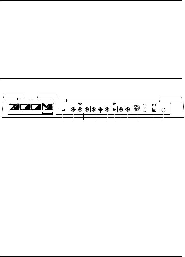
Rear Panel
INPUT GAIN |
|
EXT |
|
OUTPUT |
EXT |
MIDI OUT |
|
|
INPUT |
SEND RETURN |
R |
L/MONO PHONES |
VOLUME MANUAL CTRL OUT |
DC9V 200mA |
POWER |
||
H M L |
||||||||
|
|
|
|
|
|
|
MODEL 4040 ZOOM CORPORATION
MADE IN JAPAN/FABRIQUE AU JAPON SERIAL NO
(1) |
(2) |
(3) |
(1) INPUT GAIN SWITCH
This switch controls the input sensitivity. Select the position most suited to the connected instrument. For reference, standard settings are shown below.
H: For guitars with single-coil pickups
M: For guitars with hum-bucking or active type pickups
L:For guitars with very high output
(2)INPUT jack
Serves for connection of an instrument such as electric guitar or bass.
(3) EXTERNAL SEND/RETURN connectors
Serve for connection of an external effect device. The send/return loop is inserted in series between the compressor and distortion sections in the PRE module. The ON/OFF setting of the send/return loop can be stored as part of a patch.
(4) OUTPUT L/MONO & R connectors
Serves for connection to a guitar amplifier. To use the 4040 in stereo, connect cables to both jacks. For a monaural setup, connect the cable to the L/MONO jack.
(5) PHONES jack
Allows connection of a pair of stereo headphones, to monitor the output of the 4040.
(4) |
(5) |
(6) |
(7) |
(8) |
(9) |
(10) |
(11) |
(6) VOLUME control
Adjusts the master volume (overall output level of the 4040). The control affects both the signal at the OUTPUT connectors and the PHONES jack.
(7) MANUAL connector
This jack serves for connection of the optional foot switch FS01 which can be used to switch between Play mode and Manual mode.
(8) EXTERNAL CONTROL OUT connector
This jack can be used to control channel switching of an external guitar amplifier.
This setting can be stored as part of a patch.
(9) MIDI OUT connector
Serves for connection of a device with MIDI input, such as another effect or a synthesizer. The setting can be stored as part of a patch.
(10) DC INPUT (AC adapter) jack
The supplied AC adapter is connected here.
(11) POWER switch
Serves to turn the 4040 on and off.
5
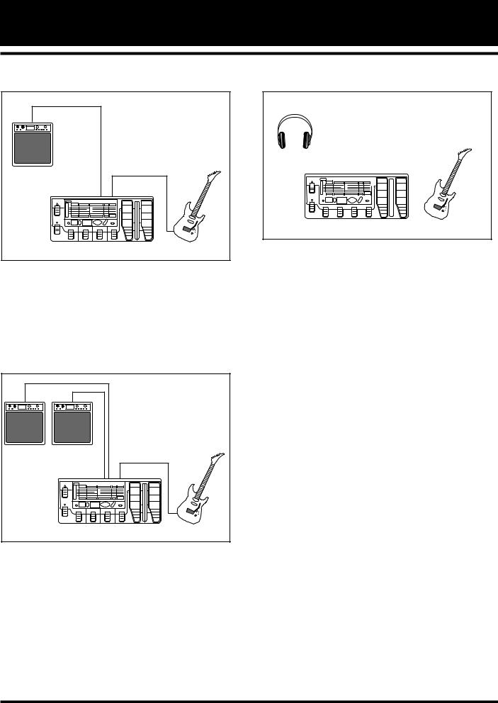
Connection Examples
Connection to one guitar amplifier (Example 1)
Guitar Amplifier |
|
OUTPUT L/MONO |
INPUT |
4040 |
|
To use the 4040 with one guitar amplifier, connect the output of the musical instrument to the INPUT jack of the 4040, and the OUTPUT L/MONO jack of the 4040 to the amplifier. With this connection, stereo effects such as reverb and ping-pong delay are output in mono.
Connection to two guitar amplifiers (Example 2)
Guitar Amplifiers |
OUTPUT R |
|
OUTPUT |
INPUT |
|
L/MONO |
||
|
||
|
4040 |
To use the 4040 with two guitar amplifiers, connect the OUTPUT L/R jacks of the 4040 to the amplifiers. A well balanced stereo sound can be obtained when the stereo effects are activated.
Connection to Headphone (Example 3)
|
|
|
|
|
|
|
|
|
|
|
|
|
|
|
|
|
|
|
|
|
|
|
|
|
|
|
|
|
|
|
|
PHONES OUT |
|
|
|
INPUT |
|
|
|
||||||||
|
|
|
|
|
|
|
|
|
|
|
|
|
|
|
|
|
|
|
|
|
|
|
|
|
|
|
|
|
|
|
|
|
|
|
|
|
|
|
|
|
|
|
|
|
|
|
|
|
|
|
|
|
|
|
|
|
|
|
|
|
|
|
|
|
|
|
|
|
|
|
|
|
|
|
|
|
|
|
|
|
|
|
|
|
|
|
|
|
|
|
|
|
|
|
|
|
|
|
|
|
|
|
|
|
|
|
|
|
|
|
|
4040
This setup is suitable for example to practice individually without disturbing others.
6
Playing a Patch (Use of the Play Mode)
In the Play mode, a patch is selected and played. This section describes the basic operation steps for selecting patches.
•Turn off the amplifier and set the volume control to minimum. Then connect the 4040 to the instrument and amplifier.
•Turn on the 4040 and then the amplifier. Adjust the volume to a suitable position while playing the instrument.
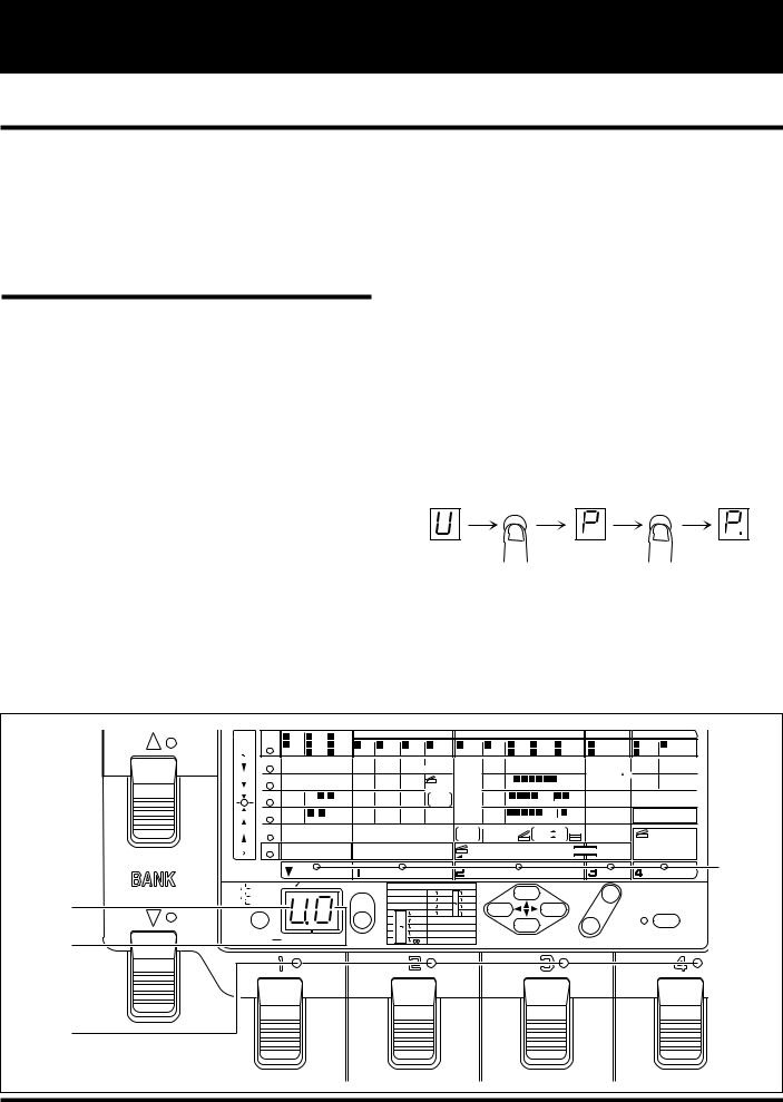
Panel display in Play mode
When the 4040 is turned on, it goes into Play mode automatically. In the Play mode, the following information is shown on the display.
(1)Group
The currently selected group is shown in the GROUP field.
(2)Bank number
The currently selected bank number is shown in the BANK field.
(3)Patch number
The currently selected patch number is indicated by the pedal LED (1 - 4).
(4)Effect module on/off
Selecting a patch
• Select the desired group with the GROUP key.
In the 4040, patches are divided into the USER group for patches which can be created and altered freely and stored by the user, and the PRESET group for factory defined patches where only the output level can be changed, but not stored. Choose the group from which you want to select a patch.
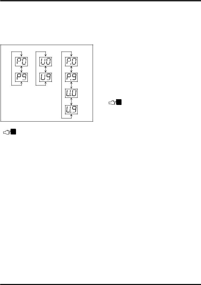
With each push of the GROUP key, the group setting cycles through the following three settings which are shown on the display.
• U (USER) |
USER group only |
•P (PRESET) PRESET group only
•U. or P. (BOTH) USER group and PRESET group
The effect module on/off condition in the patch is indicated by the module cursor LED.
DELAY TIME |
|
PRE MODULE |
|
|
|
|
|
|
|
|
|
|
|
|
|
|
|
|
|
|
|
|
|
|
|
|||||
BANK TAP EDIT |
|
|
|
|
|
|
|
|
|
|
|
|
|
|
|
|
|
|
|
|
|
|
|
|
||||||
|
|
|
|
|
|
|
|
|
|
|
|
|
|
|
|
|
|
|
|
|
|
|
|
|
|
|
|
|
||
TUNER |
EFFECT |
1 |
CLN I |
3 |
ODI |
4 |
ODII |
|
|
|
EQ |
|
|
|
MODULATION |
|
|
|
|
DELAY |
|
REVERB |
||||||||
2 |
CLN II |
5 |
DST I |
6 |
DST II |
1 EQ |
2 |
AMP |
3 |
AUTO |
4 |
PDL |
1 PDL |
2 PIT |
3 |
FLG |
|
4 |
PHA |
5 |
TREM |
1 |
MONO |
1 |
HALL |
3 DELAY |
||||
(BYPASS) |
|
|
||||||||||||||||||||||||||||
|
|
|
7 |
LEAD 8 |
METAL |
|
|
SIM |
|
WAH |
|
WAH |
PIT |
|
6 |
STEP |
7 |
SLOW |
8 |
CHO |
2 |
PPD |
2 |
ROOM |
||||||
|
|
|
|
|
|
|
|
|
||||||||||||||||||||||
|
PARM 1 |
|
COMP |
|
|
|
HIGH |
COLOR |
|
FREQ |
|
FREQ |
|
PITCH |
|
|
|
|
DEPTH |
|
|
|
|
[0– 10] |
|
TIME |
TIME |
|||
|
|
|
[0– 4] |
|
|
|
[-7– +7] |
|
[1– 3] |
|
[1–64] |
|
|
[0– 24] |
|
|
|
|
|
[0–10] |
|
|
|
|
(X100mS) |
|
[1– 10] [0– 90] (X10mS) |
|||
|
PARM 2 |
|
TONE |
|
|
|
MID |
|
BOX |
|
SENS |
|
EXP. |
MODE |
SHIFT |
|
3 |
4 |
5 |
6 7 8 |
RATE |
|
DELAY TIME( |
) |
TONE |
FEEDBACK |
||||
|
|
|
|
|
|
|
|
|
|
[0– 99] |
|
|||||||||||||||||||
|
|
|
[-7–+7] |
|
|
|
[-7– +7] |
|
[1– 3] |
|
[0–10] |
|
MODE |
[1–16] |
[dn, UP] |
|
|
|
|
|
[1–50] |
|
|
|
|
(mS) |
|
[-7– +7] |
[0– 10] |
|
|
PARM 3 |
|
|
|
3 – 8 |
GAIN |
MIDf |
DEPTH |
|
|
0= NORM |
(PITCH) |
FINE |
3 |
4 |
|
5 |
6 PEAK |
7 |
8 |
BAL. |
|
FEEDBACK |
|
|
MIX |
||||
|
|
|
|
|
|
|
|
|
|
|
||||||||||||||||||||
|
|
|
|
|
[1–16] |
|
[1–16] |
|
[0–10] |
|
|
1= INV |
|
[-5– +5] |
|
|
|
|
|
[0–10] |
|
|
|
|
[0– 10] |
|
[0– 10] |
|||
|
PARM 4 |
|
|
3 – 8 |
DYNAMICS |
LOW |
|
TONE |
|
|
|
|
|
BAL |
3 |
4 |
5 |
|
6 |
7 MODE |
8 |
STR |
|
MIX |
|
PATCH LEVEL |
||||
|
|
|
|
|
[0– 3] |
|
[-7– +7] |
[-7– +7] |
|
|
|
|
|
[0– 10] |
|
|
|
|
|
[0, 1] |
|
|
|
|
[0– 10] |
|
|
[0– 50] |
||
|
PARM 5 |
|
ZNR |
|
|
|
|
|
|
LEVEL |
|
|
0= NORM |
EXP.MODE |
|
|
|
|
0= min |
VAL |
|
|
|
|
EXP. SELECT |
|||||
|
|
|
[0–15] |
|
|
|
|
|
|
[1– 8] |
|
|
1= INV |
|
|
|
|
|
|
1= VAL |
max |
|
|
|
|
|||||
|
|
|
|
|
|
|
|
|
|
|
|
|
|
|
|
|
|
|
|
|
|
[0– 5] |
||||||||
|
|
|
|
|
|
|
|
|
|
|
|
|
|
|
|
|
|
|
|
|
|
|
|
|
|
|
|
|
|
|
TOTAL |
EXTERNAL LOOP |
EXTERNAL CONTROL OUT |
|
MINIMUM VOLUME |
GLOBAL |
MIDI CH |
0= OFF |
1= DIST |
2= EQ |
|
[0,1] 0=OFF, 1=ON |
[1– 4] |
|
[0–10] |
[1– 16] |
||||
|
VOL |
|
3= MOD |
4= DLY |
5= REV |
||||
|
|
|
|
|
|
|
|
BANK |
|
|
|
|
|
|
|
|
(4) |
|
|
PRE MODULE |
|
|
EQ |
|
|
|
MODULATION |
DELAY |
REVERB |
|
USER |
(EDIT TUNER VALUE) |
|
|
|
POL–PIT MODE |
|
|
TUNER CALIB |
||
|
|
|
|
|
|
|
|||||
|
|
|
1: Dirty BEND |
9: |
b3rd |
3rd |
|
||||
|
PRESET |
|
|
|
(435Hz–445Hz) |
||||||
(1) |
( ) |
|
|
2: Ham |
Chokin 10: 1Oct |
1Oct |
+ |
|
|||
BOTH |
|
STORE |
3: Detune |
11: |
5th |
4th |
|
||||
|
|
|
|||||||||
|
|
|
|
4: |
|
2nd |
12: |
5th |
6th |
– |
|
|
|
|
|
5: |
|
1Oct |
13: 4 Octave |
|
|
|
|
|
|
|
|
6: |
0 |
1Oct |
14: Hi-BAND |
|
VALUE |
EDIT(MANUAL) |
|
(2) |
GROUP |
GROUP BANK |
|
7: |
|
2Oct |
15: X-fade |
PARAMETER SELECT |
|||
|
8: |
|
|
16: Scratch |
|
CANCEL |
|||||
|
|
|
|
|
|
|
|
|
|
|
|
(3)
7
• Select the bank with the BANK 
 pedals.
A bank is a group of four patches. There are ten banks each (numbered 0 through 9) for the USER group and the PRESET group. The BANK ▲ pedal selects the next higher bank, and the BANK ▼ pedal the next lower bank. (The bank number display flashes.)
GROUP=PRESET GROUP=USER GROUP=BOTH
NOTE Merely pressing one of the BANK pedals does not yet change the patch. To activate the patch and change the sound, press one of the pedal switches 1 - 4, as described below.
•Select the patch by pressing one of the pedal switches 1 – 4.
The LED of that pedal lights up, showing that the patch has been selected. (The BANK number is now constantly lit.)
Now would be a good time to try out some of the various patches offered by the 4040 while playing your instrument.
Useful functions in the Play mode
Some other useful functions available in Play mode are described below.
■ Adjusting the patch level
The final output level of the patch — called the patch level
— is also stored as a parameter along with the other parameters of the patch. In the Play mode, the patch level can be adjusted.
•Press the VALUE + / - keys in the Play mode.
When one of the VALUE + / - keys is pressed, the current patch level setting is shown on the display as a numeric value (0 – 50). Pressing VALUE + increases the value and pressing VALUE - decreases it. To change values continuously, hold down the key. To change values more rapidly, press the other key as well.
NOTE The patch level setting change made in this way is only temporary. If you select a different patch without storing the new level setting first, the setting will be lost. (For details on how to store settings, please refer to page 12.)
In the Play mode, the patch level can be adjusted also for patches from the PRESET group, but the new level setting cannot be stored. When wishing to store the level, select a patch from the USER group.
■ Bypassing the effects
You can temporarily turn off all effects in a patch. This is useful for example to check the sonic character of a patch. The bypass mode is also used for the chromatic tuning function.
•In the Play mode, press the pedal switch 1 - 4 whose LED is lit (i.e. the pedal switch that was used to choose the current patch).
All effects in the patch are now bypassed and the original instrument sound is heard. In the bypass condition, the LED of the selected patch flashes and the tuner LED lights up.
•Press the pedal switch once more to turn the patch on again. Normal Play mode can also be restored by selecting a different patch.
■ Tuning a guitar
The 4040 incorporates an automatic guitar tuning function. When the 4040 is set to the bypass mode, the tuning function is automatically enabled.
•In the Play mode, press the pedal switch 1 – 4 whose LED is lit. This activates the bypass mode and the tuner LED lights up.
8
 Loading...