


OPERATION MANUAL
Using the MIDI Control Function • • • • • 10
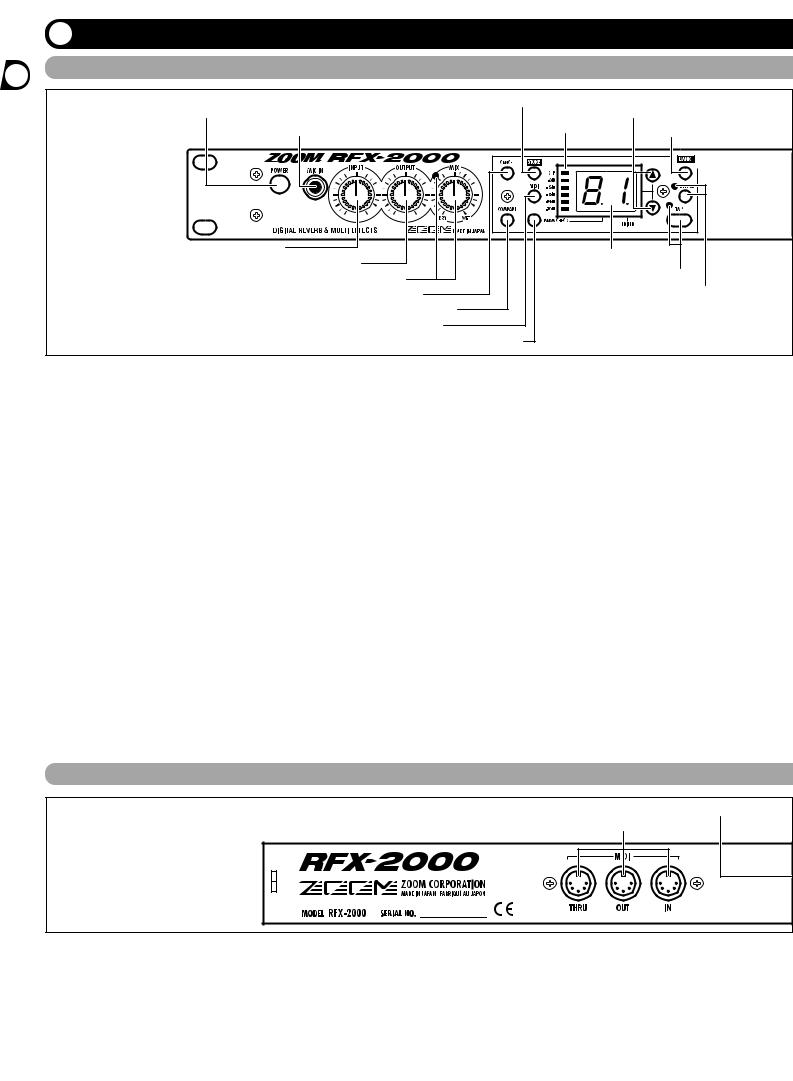
Front Panel
(1) POWER switch |
(10) STORE key |
(12) VALUE UP/DOWN keys |
|||
|
|
||||
|
(2) MIC IN jack |
(11) |
Level meter |
(13) BANK key |
|
|
|
|
|
||
(3) |
INPUT control |
|
|
(14) Display |
|
|
(4) OUTPUT control |
|
|
|
|
|
(5) MIX control and LED |
|
(15) TAP key and LED |
||
|
(6) CANCEL key |
|
(16) BYPASS key and LED |
||
|
(7) COMPARE key |
|
|
|
|
|
(8) |
MIDI key |
|
|
|
|
|
(9) PARM CHECK key |
|
|
|
(1)POWER switch
Serves to turn the unit on and off.
(2)MIC IN jack
A dynamic microphone with an output impedance of about 600 ohms can be connected here. Normally the input signal from this jack is mixed with the signal from the rear-panel INPUT jacks and sent to the internal effect circuitry. When the VOCODER effect is selected, the mike input signal serves for controlling the sound character and the envelope (volume change curve) of the effect.
(3)INPUT control
Serves to adjust the signal from the INPUT jacks and the MIC IN jack.
(4)OUTPUT control
Serves to adjust the level of the signal supplied at the OUTPUT jacks.
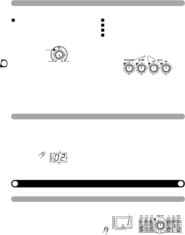
(5)MIX control and LED
Serves to adjust the balance between original sound (DRY) and effect sound (WET). When the control is
turned fully counterclockwise, only the original sound is output. When the control is turned fully clockwise, only the effect sound is output. If the mixing balance setting was changed since the last store operation, the LED lights up.
(6)CANCEL key
Serves to cancel a store operation.
(7)COMPARE key
When a patch (group of stored effect settings) is being edited, this key can be used to compare the sound before and after the edit.
(8)MIDI key
This key is used to make various MIDI settings.
(9)PARM CHECK key
Serves for checking effect parameter settings.
(10)STORE key
Used for storing patches in memory and other functions.
(11)Level meter
These indicators show the signal input level.
Rear Panel
(2) BYPASS jack
(1) MIDI connectors
(1)MIDI connectors
Serves for connection to the MIDI interface of a computer or to a MIDI keyboard or similar. This allows patch switching from external equipment or control of the entire operation of the RFX-2000 from a computer, using the supplied editor/librarian software.
(2)BYPASS jack
Serves for connection of the foot switch FS01 (option) for switching effects on and off.
(3)DIGITAL OUT connectors
The same signal as available at the OUTPUT jacks is carried by these connectors in S/PDIF digital format. This can be used to supply the signal to consumer equipment with a digital input, such as a digital multitrack recorder,
2 ZOOM RFX-2000
Controls and Functions 
Front Panel
|
|
|
|
|
|
|
(17) BANK LEDs |
|
|
(19) REV CHARACTER (EDIT 1) control and LED |
|||||||||||||||||||||||||||||||||||||||||
|
|
|
|
|
|
|
|
|
|
|
|
|
|
|
|
|
|
|
|
|
|
|
|
|
|
|
|
|
|
|
|
|
|
|
(20) REV TIME (EDIT 2) control and LED |
||||||||||||||||
|
|
|
|
|
|
|
|
|
|
|
|
|
|
|
|
|
|
|
|
|
|
|
|
|
|
|
|
|
|
|
|
|
|
|
|||||||||||||||||
|
|
|
|
|
|
|
|
|
|
|
|
|
|
|
|
|
|
|
|
|
|
|
|
|
|
|
|
|
|
|
|
|
|
|
|
|
|
|
|
|
|
|
|
|
|
|
|
|
|
|
|
|
|
|
|
|
|
|
|
|
|
|
|
|
|
|
|
|
|
|
|
|
|
|
|
|
|
|
|
|
|
|
|
|
|
|
|
|
|
|
|
|
|
|
|
|
|
|
|
|
|
|
|
|
|
|
|
|
|
|
|
|
|
|
|
|
|
|
|
|
|
|
|
|
|
|
|
|
|
|
|
|
|
|
|
|
|
|
|
|
|
|
|
|
|
|
|
|
|
|
|
|
|
|
|
|
|
|
|
|
|
|
|
|
|
|
|
|
|
|
|
|
|
|
|
|
|
|
|
|
|
|
|
|
|
|
|
|
|
|
|
|
|
|
|
|
|
|
|
|
|
|
|
|
|
|
|
|
|
|
|
|
|
|
|
|
|
|
|
|
|
|
|
|
|
|
|
|
|
|
|
|
|
|
|
|
|
|
|
|
|
|
|
|
|
|
|
|
|
|
|
|
|
|
|
|
|
|
|
|
|
|
|
|
|
|
|
|
|
|
|
|
|
|
|
|
|
|
|
|
|
|
|
|
|
|
|
|
|
|
|
|
|
|
|
|
|
|
|
|
|
|
|
|
|
|
|
|
|
|
|
|
|
|
|
|
|
|
|
|
|
|
|
|
|
|
|
|
|
|
|
|
|
|
|
|
|
|
|
|
|
|
|
|
|
|
|
|
|
|
|
|
|
|
|
|
|
|
|
|
|
|
|
|
|
|
|
|
|
|
|
|
|
|
|
|
|
|
|
|
|
|
|
|
|
|
|
|
|
|
|
|
|
|
|
|
|
|
|
|
|
|
|
|
|
|
|
|
|
|
|
|
|
|
|
|
|
|
|
|
|
|
|
|
|
|
|
|
|
|
|
|
|
|
|
|
|
|
|
|
|
|
|
|
|
|
|
|
|
|
|
|
|
|
|
|
|
|
|
|
|
|
|
|
|
|
|
|
|
|
|
|
|
|
|
|
|
|
|
|
|
|
|
|
|
|
|
|
|
|
|
|
|
|
|
|
|
|
|
|
|
|
|
|
|
|
|
|
|
|
|
|
|
|
|
|
|
|
|
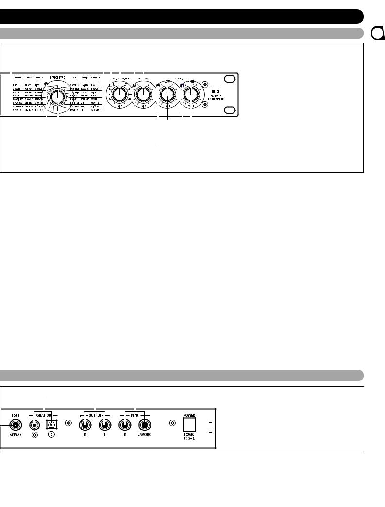
(18) EFFECT TYPE selector and LED |
(22) REV EQ HIGH (EDIT 4) control and LED |
(21) REV EQ LOW (EDIT 3) control and LED
(12) VALUE UP/DOWN keys |
(17) BANK LEDs |
Serve for switching patches and changing parameter values. Holding down one key while pressing the other results in a fast change.
(13)BANK key
Serves to select the effect bank (group of effects arranged by general type).
(14)Display
Shows various information such as patch numbers and parameter values.
(15)TAP key and LED
This key serves for tap input of time-based parameters such as delay time and rate. When an effect where tap input can be used is selected, the LED flashes with a frequency that indicates the current setting. When an effect where tap input cannot be used is selected, the LED is out.
(16)BYPASS key and LED
These indicators show which bank is currently selected. When the EXTRA bank (only selectable with the supplied software) is selected, all six LEDs are lit.
(18)EFFECT TYPE selector and LED
Serves to choose an effect from the currently selected bank. If the setting was changed since the last store operation, the LED lights up.
(19)REV CHARACTER (EDIT 1) control and LED
(20)REV TIME (EDIT 2) control and LED
(21)REV EQ LOW (EDIT 3) control and LED
(22)REV EQ HIGH (EDIT 4) control and LED
These controls allow the user to adjust effect parameters to a desired value. Which parameters can be adjusted depends on the currently selected effect. If a setting was changed since the last store operation, the respective LED lights up.
Serves to set the unit to the bypass condition where only the original sound is output. In this condition, the LED is lit.
Rear Panel
(3)DIGITAL OUT connectors
(4)OUTPUT jacks (5) INPUT jacks


 (6) POWER (AC adapter) connector
MD recorder, or DAT recorder. The optical and coaxial output connectors can be used at the same time. The OUTPUT control is not active in this case.
(4)OUTPUT jacks
Connect these jacks to the recorder or playback system.
(5)INPUT jacks
Connect a line-level source, such as an instrument or CD
player to these jacks. If a plug is inserted only in the L/MONO jack, the signal from this plug will be supplied to both channels.
(6)POWER (AC adapter) connector
The supplied AC adapter is to be connected here for powering the unit.
Functions and Controls
ZOOM RFX-2000 3
The RFX-2000 is compatible with international 19-inch rack standards (EIA, DIN). Because the unit has been designed for rack installation, it is preferable to operate the unit in this
• The RFX-2000 uses a metal frame, making the unit heavier than it might seem at first
Caution glance. While installing the unit in a rack, carefully support the weight of the unit until all screws are securely tightened. Otherwise the unit may drop, possibly causing injury to persons or damage to itself or to other equipment.
•Do not directly stack the unit on top of other equipment. Otherwise heat may
way, rather than simply placing it on a table or similar. Align the four screw holes with the rack screw holes and securely fasten the unit to the rack with screws.
lead to a fire risk or cause performance degradation.
•Before installation, always unplug any connecting cables and the AC adapter cable. Otherwise the equipment or the cables may be damaged.
•Make sure that the rack in which the unit is installed is placed on a firm, solid surface, so that it cannot shake or topple over. Otherwise there is a risk of injury to persons or damage to the unit or to other equipment.
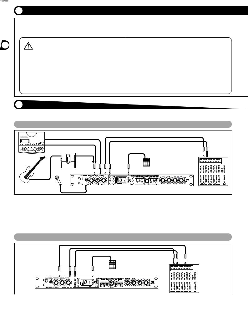
This section shows how to connect the RFX-2000 to the sound source and to the playback system.
Insert Connection
Send/Return Connection
digital multitrack recorder, MD recorder, or DAT recorder) is
4 ZOOM RFX-2000

Rack Mounting
* Rack mount screws are not supplied with the unit.
Getting Connected
Using the VOCODER Effect
MD player or sampler or similar with recorded voice
Connected Mounting/Getting Rack
Synthesizer |
INPUT |
OUTPUT |
|
L/MONO R |
L R |
Microphone |
|
|
|
MIC IN |
RFX-2000 Keyboard amplifiers |
This is a connection example for using the VOCODER effect from the SFX bank. Connect a dynamic microphone to the front-panel MIC IN jack on the RFX-2000. Connect a synthesizer or other instrument to the rear-panel INPUT L/MONO jack. You can then use the mike to vary the
envelope (volume change curve) and the sound character of the VOCODER effect.
If nothing is connected to the MIC IN jack, the signal supplied to the INPUT L/MONO jack is controlled by the signal supplied to the INPUT R jack.
Controlling the RFX-2000 Effects from a Computer
Sound source  MIDI IN module
Computer
INPUT |
OUTPUT |
L R |
L R |
MIDI |
OUT |
MIDI interface |
MIDI IN |
MIDI IN |
MIDI OUT |
RFX-2000 Playback system |
|
The supplied software can be used to edit the patches of the |
Note: For information on software installation, please |
RFX-2000, switch the patches in conjunction with other |
refer to the separate sheet. For information on |
sequencer software, and to control patch switching and make |
how to use the software, please refer to the |
parameter changes. To enable these functions, make |
documentation included on the CD-ROM. |
connections as shown above. |
|
ZOOM RFX-2000 5
This section is intended to familiarize you with the basic operation steps of the RFX-2000.
Power UP
1. Verify that the AC adapter, sound source, and playback system are correctly connected to the RFX-2000.
The INPUT control and OUTPUT control of the RFX2000 as well as the volume control of the playback system should be set to minimum.
2. Turn on the system in the following order: sound source RFX-2000 playback system.
3. While playing the sound source, turn up the
INPUT control of the RFX-2000 to adjust the input level.
To minimize noise and distortion, the INPUT control should be set as high as possible without causing the CLIP LED to light.
4. Adjust the OUTPUT control and the volume control of the playback equipment to obtain a suitable playback volume.
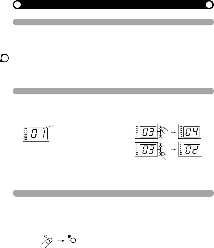
Selecting a Patch
The memory of the RFX-2000 contains 100 stored patches. The display shows the number of the currently selected patch (01, 02,...99, 00). This condition is called the play mode.
To switch patches, proceed as described below. We suggest that you simply try out various patches to see what kind of sound the unit can produce.
CLIP |
|
-6dB |
|
-12dB |
|
-24dB |
|
-36dB |
|
-48dB |
|
PARM CHECK |
EDITED |
|
Number of the currently selected patch
(01, 02,...99, 00)
1. Use the VALUE UP/DOWN keys to select the number of the desired patch.
The VALUE UP key switches to higher patch numbers and the VALUE DOWN key to lower patch numbers.
2. While playing the instrument or producing sound from the sound source, switch patches to check out the resulting sound.
Bypassing the Effects
You can temporarily turn effect processing off, so that only the original sound is output. This is useful to quickly check the change brought about by an effect.
1. To set the RFX-2000 to the bypass mode, press the BYPASS key while the unit is in play mode.
BYPASS |
BYPASS |
The BYPASS indicator lights up.
The RFX-2000 has two different bypass states, depending on the effect in the currently selected patch. (For information on which effects use which bypass type, please refer to pages 14 - 23.)
•WET MUTE
In this condition, only the effect sound is muted and the original sound is output. The level of the original sound output depends on the MIX control position. Therefore there may be a drop in volume or the sound may be entirely cut off.
•DRY THRU
The original sound is output without any processing. The setting of the MIX control has no effect on the volume level.
2.To cancel the bypass mode and return the RFX-2000 to the normal state, press the BYPASS key once more.
6 ZOOM RFX-2000
A patch called up from memory can be edited using the front-panel controls. You can for example select different effects and adjust effect intensity and other parameters.
If any parameter is changed from the stored condition, the new parameter value is shown on the display for about 2 seconds, and the EDITED mark (.) at the right edge of the display
|
Parameter |
LED lights |
changed |
EDITED mark (.) shown |
|
EDITED |
|
appears. This indicates that the current patch has been edited. Because the LED of the control knob that was used to adjust the value also lights, it is easy to see which parameter has been edited.
Note:
When the effect is changed, the LEDs of all control knobs except the MIX control light up.
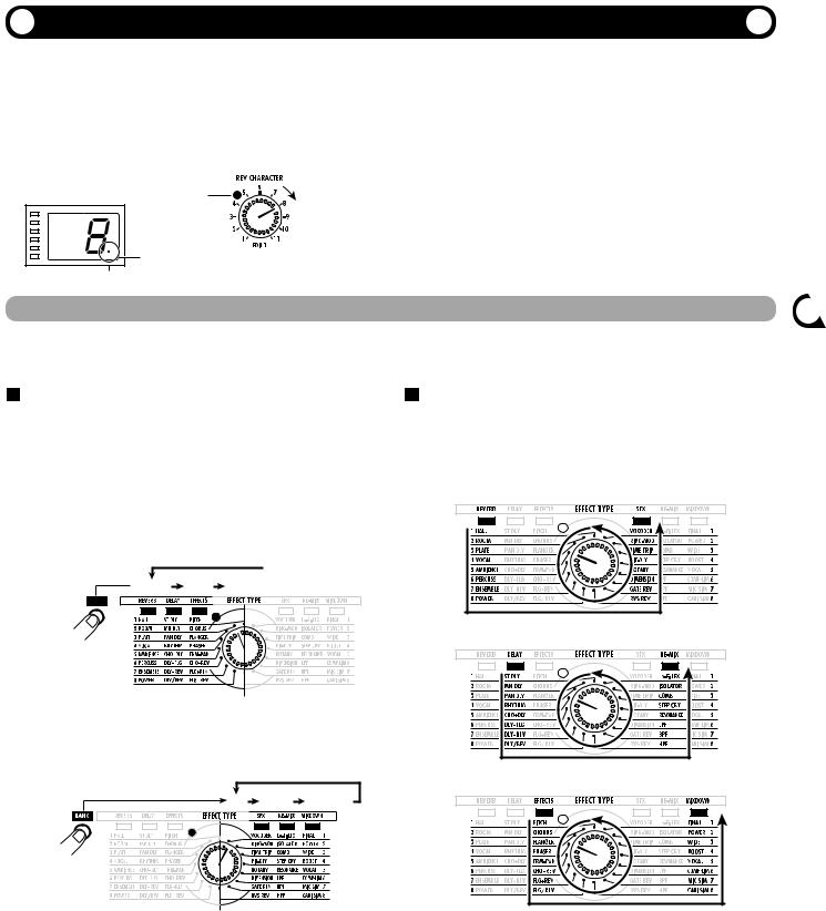
Selecting an Effect
The effect determines the type of sound processing that is performed. To select an effect, use the BANK key and EFFECT TYPE selector.
depends on the current BANK position.
• Left side BANK selected
Pressing the BANK key cycles through the following banks: REVERB DELAY EFFECTS REVERB etc.
Bank switching
 REVERB DELAY EFFECTS
BANK
setting currently selected with the BANK key.
REVERB or SFX bank selected
DELAY or RE-MIX bank selected
BANK key
• Right side BANK selected
Pressing the BANK key cycles through the following banks: SFX RE-MIX MIXDOWN SFX etc.
Bank switching |
EFFECTS or MIXDOWN bank selected |
|
|
SFX RE-MIX MIXDOWN |
|
BANK key
•When a changed bank is returned to the original setting, the respective BANK LED flashes for 1 second.
Note:
For patches where the EXTRA bank is selected, all six BANK LEDs light up.
•When the EFFECT TYPE selector is moved, the display shows the effect number (1 - 8 in the normal banks) for about 2 seconds.
•When the effect number is changed from the last stored condition, the LED of the EFFECT TYPE selector lights up. When the setting is returned to the original effect, the LED goes out.
•When calling up a patch, the LED of the bank where the patch is stored lights up.
Patch a Editing
ZOOM RFX-2000 7
Changing the Value of an Effect Parameter
Each effect of the RFX-2000 consists of certain effect parameters which determine the intensity and tone character of the effect. Effect parameters can be adjusted with the following edit controls.
Storing an Edited Patch
If an edited patch is not stored in memory, the edited contents will be lost when another patch is selected. When wishing to keep the edited patch, store it in memory as follows.
1.
2.
3.
Select the patch and edit it. |
the patch. |
|||||||
Press the STORE key. |
When wishing to use the same patch number, this step is |
|||||||
not necessary. |
||||||||
The patch number on the display flashes. |
||||||||
4. Press the STORE key once more to execute |
||||||||
|
|
|
|
|
||||
|
STORE |
|||||||
|
|
|
|
|
|
|
the store operation. |
|
|
|
|
|
|
|
|
||
|
|
|
|
|
|
|
||
|
|
|
|
|
|
|
||
STORE key |
|
|
|
|
The patch is stored in memory and the flashing of the |
|||
|
|
|
|
|||||
|
|
|
|
|||||
|
|
|
|
|||||
|
|
|
|
|||||
|
|
|
|
|||||
|
|
|
|
display stops. |
||||
|
|
|
|
|||||
|
|
|
|
|
|
|
||
|
|
|
|
|
|
|
||
Use the VALUE UP/DOWN keys to select the |
If you press the CANCEL key instead of the STORE key, |
|||||||
the operation is aborted and the unit reverts to the |
||||||||
patch number in which you want to store |
||||||||
condition of step 1. |
||||||||
|
|
|
|
|
|
|
||
The RFX-2000 offers various handy functions for editing patches.
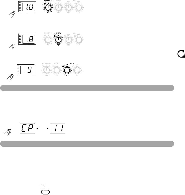
Checking the parameter value (parameter check)
You can also check a parameter value without moving its associated front-panel control.
1. Press the PARM CHECK key.
The PARM CHECK mark (.) in the center of the display appears and the EFFECT TYPE selector LED flashes for about 2 seconds.
This indicates that the effect setting is being checked. The number of the currently selected effect (1 - 8) is shown for about 2 seconds on the display. The display then reverts to the original condition.
|
Effect number |
|
|
LED flashes |
|
|
|
||
|
|
|
|
|
|
|
|
|
|
|
|
|
|
|
|
|
|
|
|
|
|
|
|
|
|
|
|
|
|
|
|
|
|
|
|
|
|
|
|
|
|
|
|
|
|
|
|
|
|
|
|
|
|
|
|
|
|
|
|
|
|
|
|
|
|
|
|
|
|
|
|
|
|
|
PARM CHECK
PARM CHECK mark (.)
PARM CHECK key
2. To check another parameter, press the PARM CHECK key again before the display indication reverts to the previous condition.
8 ZOOM RFX-2000
With each push of the PARM CHECK key, the parameter to be checked is advanced successively.
REV CHARACTER
Parameter adjusted with REV CHARACTER (EDIT 1) control
PARM CHECK
REV TIME
Parameter adjusted with REV TIME (EDIT 2) control
PARM CHECK
REV EQ LOW
Parameter adjusted with REV EQ LOW (EDIT 3) control
PARM CHECK
Comparing the Sound Before and After Edit (Compare Function)
This function allows you to compare the currently edited sound to the sound before editing.
1. Press the COMPARE key.
The currently edited patch is temporarily returned to the condition before editing. The indication "CP" and the patch number flash alternately on the display, and the "EDITED" mark is out.
COMPARE key |
|
Shown |
||
alternately |
||||
COMPARE |
||||
|
|
|
||
2. To return to editing, press the COMPARE key once more (or press the CANCEL key).
•If desired, you can check the original value of each parameter by pressing the PARM CHECK key while the unit is in the compare mode.
•Moving any of the controls in compare mode has no effect.
Setting Parameters With the Tap Key (Tap Input)
The RFX-2000 allows input of time-based parameters by tapping the TAP key at the desired intervals. For example, the flanger modulation speed or delay time can be easily matched to the tempo of a song in this way.
1. Select a patch for which tap input is possible.
Whether tap input is possible or not depends on the effect selected for that patch (see pages 14 - 23). When a patch for which tap input is possible is selected, the TAP LED flashes.

 TAP
TAP
2. Hit the TAP key several times in the desired interval.
The delay time or rate is set according to the tap interval and the tap beat parameter set for the respective patch (see page 12).
3. If desired, store the patch.
The parameter changed by tap input will revert to the original setting when the patch is switched. If wishing to retain the change, you should therefore store the patch.
•The parameter which can be set by tap input is preset (see pages 14 - 23).
•The maximum interval that can be measured by the tap input function is 2 seconds.
•If the tap input interval is outside the setting range for that parameter, it will be corrected to an acceptable value.
•If a parameter was set by tap input and is then changed by moving the control knob for that parameter, the control knob setting will override the tap input.
Functions Useful
ZOOM RFX-2000 9
 Loading...