


Operation Manual
© ZOOM Corporation
Reproduction of this manual, in whole or in part, by any means, is prohibited.

SAFETY PRECAUTIONS Usage Precautions
SAFETY PRECAUTIONS
In this manual, symbols are used to highlight warnings and cautions for you to read so that accidents can be prevented. The meanings of these symbols are as follows:
|
This symbol indicates explanations about extremely |
|
dangerous matters. If users ignore this symbol and |
Warning |
handle the device the wrong way, serious injury or |
|
death could result. |
|
This symbol indicates explanations about dangerous |
|
matters. If users ignore this symbol and handle the |
Caution |
device the wrong way, bodily injury and damage to |
|
the equipment could result. |
Please observe the following safety tips and precautions to ensure hazard-free use of the A2.
|
Power requirements |
|
Warning |
Since power consumption of this unit is fairly high, we |
|
recommend the use of an AC adapter whenever |
||
|
||
|
possible. When powering the unit from batteries, use |
|
|
only alkaline types. |
[AC adapter operation]
•Be sure to use only an AC adapter which supplies 9 V DC, 300 mA and is equipped with a "center minus" plug (Zoom AD-0006). The use of an adapter other than the specified type may damage the unit and pose a safety hazard.
•Connect the AC adapter only to an AC outlet that supplies the rated voltage required by the adapter.
•When disconnecting the AC adapter from the AC outlet, always grasp the adapter itself and do not pull at the cable.
•During lightning or when not using the unit for an extended period, disconnect the AC adapter from the AC outlet.
[Battery operation]
•Use four conventional IEC R6 (size AA) batteries (alkaline).
•The A2 cannot be used for recharging.
•Pay close attention to the labelling of the battery to make sure you choose the correct type.
•When not using the unit for an extended period, remove the batteries from the unit.
•If battery leakage has occurred, wipe the battery compartment and the battery terminals carefully to remove all remnants of battery fluid.
•While using the unit, the battery compartment cover should be closed.
|
Environment |
|
Warning |
To prevent the risk of fire, electric shock or |
|
malfunction, avoid using your A2 in environments |
||
|
||
|
where it will be exposed to: |
•Extreme temperatures
•Heat sources such as radiators or stoves
•High humidity or moisture
•Excessive dust or sand
•Excessive vibration or shock
|
Handling |
|
Warning |
• Never place objects filled with liquids, such as vases, on |
|
the A2 since this can cause electric shock. |
||
|
•Do not place naked flame sources, such as lighted candles, on the A2 since this can cause fire.
•The A2 is a precision instrument. Do not exert undue pressure on the keys and other controls. Also take care not to drop the unit, and do not subject it to shock or excessive pressure.
•Take care that no foreign objects (coins or pins etc.) or liquids can enter the unit.
Connecting cables and input and output
Caution jacks
You should always turn off the power to the A2 and all other equipment before connecting or disconnecting any cables. Also make sure to disconnect all connection cables and the power cord before moving the A2.
|
Alterations |
|
Warning |
Never open the case of the A2 or attempt to modify the |
|
product in any way since this can result in damage to |
||
|
||
|
the unit. |
|
|
Volume |
|
Caution |
Do not use the A2 at a loud volume for a long time |
|
since this can cause hearing impairment. |
||
|
Usage Precautions
Electrical interference
For safety considerations, the A2 has been designed to provide maximum protection against the emission of electromagnetic radiation from inside the device, and protection from external interference. However, equipment that is very susceptible to interference or that emits powerful electromagnetic waves should not be placed near the A2, as the possibility of interference cannot be ruled out entirely.
With any type of digital control device, the A2 included, electromagnetic interference can cause malfunctioning and can corrupt or destroy data. Care should be taken to minimize the risk of damage.
Cleaning
Use a soft, dry cloth to clean the A2. If necessary, slightly moisten the cloth. Do not use abrasive cleanser, wax, or solvents (such as paint thinner or cleaning alcohol), since these may dull the finish or damage the surface.
Please keep this manual in a convenient place for future reference.
2 |
ZOOM A2 |

Contents
SAFETY PRECAUTIONS Usage Precautions |
.............................. 2 |
Features......................................................................................... |
4 |
Terms Used in This Manual ......................................................... |
5 |
Controls and Functions / Connections ....................................... |
6 |
Selecting a Patch .......................................................................... |
8 |
Using the Tuner ........................................................................... |
10 |
Using the Rhythm Function ....................................................... |
12 |
Editing a Patch ............................................................................ |
14 |
Storing/Copying Patches ........................................................... |
16 |
Using the Feedback Control ...................................................... |
18 |
Manual operation of feedback control ....................................... |
18 |
Automatic detection of feedback frequency ............................. |
19 |
Using Manual Mode .................................................................... |
20 |
Using an Optional Foot Switch or Pedal ................................... |
21 |
Using the foot switch (FS01) ....................................................... |
21 |
Using the expression pedal (FP01/FP02)................................... |
22 |
Restoring Factory Defaults ........................................................ |
24 |
Linking Effects ............................................................................ |
25 |
CONTROL module and GLOBAL module .................................. |
25 |
Effect Types and Parameters ..................................................... |
26 |
How to read the parameter table ............................................... |
26 |
MODEL ........................................................................................... |
27 |
MIC ................................................................................................. |
28 |
COMP/LIMIT ................................................................................... |
28 |
LO EQ ............................................................................................. |
28 |
HI EQ ............................................................................................... |
29 |
ZNR ................................................................................................. |
29 |
MOD/EFX......................................................................................... |
29 |
DELAY/REVERB ............................................................................. |
31 |
CONTROL ....................................................................................... |
33 |
GLOBAL .......................................................................................... |
34 |
Specifications .............................................................................. |
35 |
Troubleshooting .......................................................................... |
35 |
A2 Preset Pattern ............................................................ |
Back cover |
The FCC regulation warning (for U.S.A.)
This equipment has been tested and found to comply with the limits for a Class B digital device, pursuant to Part 15 of the FCC Rules. These limits are designed to provide reasonable protection against harmful interference in a residential installation. This equipment generates, uses, and can radiate radio frequency energy and, if not installed and used in accordance with the instructions, may cause harmful interference to radio communications. However, there is no guarantee that interference will not occur in a particular installation. If this equipment does cause harmful interference to radio or television reception, which can be determined by turning the equipment off and on, the user is encouraged to try to correct the interference by one or more of the following measures:
•Reorient or relocate the receiving antenna.
•Increase the separation between the equipment and receiver.
•Connect the equipment into an outlet on a circuit different from that to which the receiver is connected.
•Consult the dealer or an experienced radio/TV technician for help.
ZOOM A2 |
3 |

Features
Thank you for selecting the ZOOM A2 (simply called the "A2" in this manual). The A2 is a sophisticated effect processor for acoustic guitar with the following features.
●Latest technology for top performance
Excellent sound quality is assured by signal processing circuitry featuring 96 kHz/24 bit sampling and internal 32-bit processing. Frequency response remains flat to 40 kHz, and signal-to-noise ratio is an amazing 100 dB.
●Full array of effects optimized for acoustic guitar
Out of a versatile palette of 47 effects, up to eight (including ZNR) can be used simultaneously. In addition to standard effects such as compressor and delay/reverb, the A2 offers effects which simulate the sound of famous acoustic guitars, a mic simulator, and other specialized acoustic guitar effects.
●Select optimum characteristics for pickups and amps
The A2 allows you to select the best frequency response for your pickup and amp. This is great for eliminating sonic problems that can occur when playing an acoustic guitar through a guitar amplifier.
●Automatic suppression of acoustic feedback
The feedback control feature pinpoints the frequency where acoustic feedback (howling) occurs and provides an efficient cure. The function can be activated by foot switch during a performance.
●Advanced interface
Rotary selectors and three parameter knobs make operation extremely quick and intuitive. The muting interval when switching patches has been reduced to less than 8 milliseconds, allowing virtually seamless patch changes.
●Rhythm function and auto-chromatic tuner
Rhythm patterns created from highly realistic PCM sources are convenient for use instead of a metronome during practice or for quick session work. The auto-chromatic tuner designed for guitar makes tuning a snap.
●Support for foot switch and expression pedal
By connecting an optional foot switch (FS01) to the CONTROL IN jack, you can switch banks, specify the rhythm tempo, and switch feedback control on and off with your foot. Or use an expression pedal (FP01/FP02) to vary the volume or tone in real time.
●Dual power supply principle allows use anywhere
The A2 can be powered from four IEC R6 (size AA) batteries or an AC adapter. Continuous operating time on batteries is approximately 7.5 hours with alkaline batteries.
Please take the time to read this manual carefully, in order to get the most out of your A2 and to ensure optimum performance and reliability.
4 |
ZOOM A2 |

Terms Used in This Manual
This section explains some important terms that are used throughout the A2 documentation.
IN  MODEL
MODEL 
 MIC
MIC  COMP/LIMIT
  LO EQ
LO EQ  HI EQ
HI EQ 
 ZNR
ZNR 
 MOD/EFX
 DELAY/REVERB
  OUT
OUT
■ Effect module |
comprises information about the on/off status of each |
|
As shown in the illustration above, the A2 can be |
effect module, about the effect type used in each |
|
thought of as a combination of several single effects. |
module, and about effect parameter settings. The |
|
Each of these is referred to as an effect module. |
internal memory of the A2 holds 80 patches (40 of |
|
Among others, there is a module for ZNR (ZOOM |
these can be rewritten by the user). |
|
Noise Reduction), as well as a modeling (sound |
● Bank and area |
|
simulation) module (MODEL), compressor/limiter |
A group of ten patches is called a bank. The memory |
|
module (COMP/LIMIT), modulation/special effects |
||
of the A2 comprises a total of eight banks, labelled A |
||
module (MOD/EFX). Parameters such as effect |
||
to d and 0 to 3. Banks A - d form the user area which |
||
intensity can be adjusted for each module individually, |
||
allows read/write patches. Banks 0 to 3 are the preset |
||
and modules can be switched on and off. |
||
area of read-only. |
||
|
||
■ Effect type |
The patches within each bank are numbered 0 |
|
Most effect modules comprise several different effects |
through 9. To specify a patch, you use the format |
|
which are referred to as effect types. For example, the |
"A1" (patch number 1 from bank A), "06" (patch |
|
MOD/EFX module comprises chorus, flanger, delay, |
number 6 from bank 0), etc. |
|
phaser, and other effect types. Only one of these can |
■ Modes |
|
be selected at any time. |
||
The A2 has the following operation modes. |
||
■ Effect parameter |
||
● Play mode |
||
All effect modules have various parameters that can |
||
In this mode, patches can be selected and played. |
||
be adjusted. These are called effect parameters. |
||
● Manual mode |
||
In the A2, effect parameters are adjusted with the |
||
In this mode, you play your instrument while |
||
parameter knobs 1 - 3. Similar to the knobs on a |
||
using the foot switches to turn the MOD/EFX |
||
compact effect, these change aspects such as tonal |
||
module or the feedback control function on and |
||
character and effect intensity. Which parameter is |
||
off. The mode also is used for automatic |
||
assigned to each knob depends on the currently |
||
detection of acoustic feedback frequency. |
||
selected effect module and effect type. |
||
● Edit mode |
||
■ Patch |
||
In this mode, the effect parameters of a patch can |
||
In the A2, effect module combinations are stored and |
||
be edited (changed). |
||
called up in units referred to as patches. A patch |
||
|
Operating the A2 on batteries
1. Turn the A2 over and open the cover |
2. Insert four fresh IEC R6 |
of the battery compartment on the bottom. (size AA) batteries. |
|
A2 |
Four IEC R6 |
bottom view |
(size AA) batteries |
Latch
3.Close the cover of
the battery compartment.
Push the cover in until the latch audibly snaps into place.
Insert batteries facing  in alternate directions.
|
Latch |
Cover |
Press the latch to release |
|
it and then raise the cover. |
Use four IEC R6 (size AA) batteries.
When the batteries are getting low, the indication "bt" appears on the display.
ZOOM A2 |
5 |

Controls and Functions / Connections
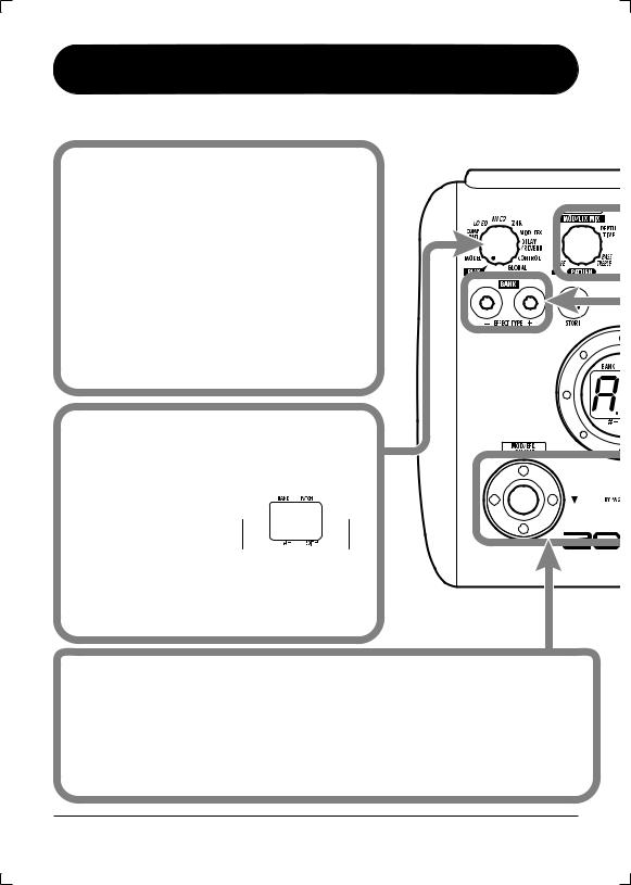
Module selector
Top Panel
Switches between play / manual mode and edit mode.
In edit mode, the knob selects the module for operation.
BANK [-]/[+] keys
In play / manual mode, the keys serve for directly switching to the next lower or higher bank.
In edit mode, the keys switch the effect type for the currently selected module.
[STORE] key
Serves for storing edited patches in memory.
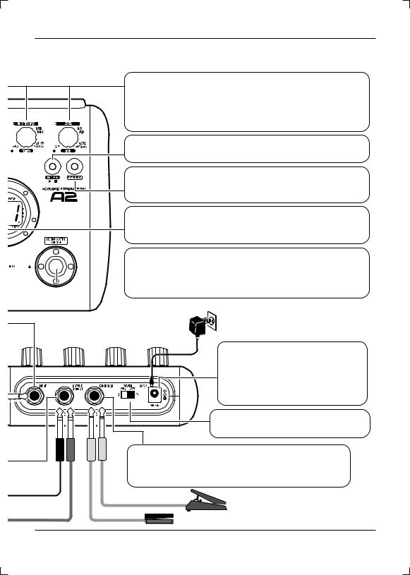
[INPUT] jack
Serves for connecting of an acoustic guitar with a pickup, an electroacoustic guitar, or an electric guitar.
■ About HI-GAIN mode
When using a magnetic pickup, a single-coil electric guitar, or any other pickup with low output level, the input gain of the A2 can be increased by selecting the HI-GAIN mode.
To start the A2 in HI-GAIN mode
Turn power on while holding down the [W] foot switch. The indication "Hi-GAin" scrolls on the display, and input gain will be set to a higher value.
NOTE
The input gain setting is not stored in memory and will be
canceled when the unit is turned off. Perform the above Acoustic guitar procedure every time at power-on, as needed.
[OUTPUT/PHONES] jack |
|
|
This stereo phone jack can be used for |
|
|
connection to a guitar amplifier or hi-fi |
|
|
system. It is also possible to use a Y cable for |
|
|
sending the output to two amplifiers, or to |
Headphones |
|
plug a pair of stereo headphones into this jack. |
||
PA system |
||
|
6 |
ZOOM A2 |
Controls and Functions / Connections
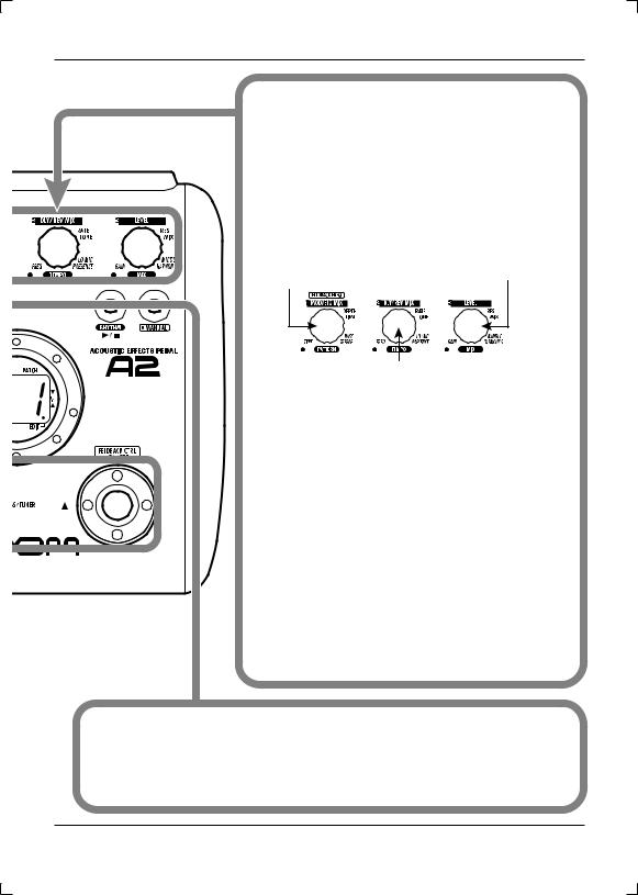
Parameter knobs 1 - 3
These knobs allow changing the value of effect parameters or the level of the overall patch. During rhythm playback, the knobs let you select a pattern, set the tempo, and adjust the rhythm volume.
RHYTHM [R/P] key
Serves to start/stop rhythm playback.
[MANUAL] key
Switches between play mode and manual mode. The key is lit when the A2 is in manual mode.
Display
Shows patch numbers, setting values, and other information about operating the A2.
[W]/[Q] foot switches
These switches serve for selecting patches, turning effect
 modules on and off, controlling the tuner, and other
  functions.
Rear Panel
AC adapter
[DC 9V] jack
An AC adapter (ZOOM AD-0006) with a rated output of 9 volts DC, 300 mA (center minus plug) can be plugged into this jack.
[POWER] switch
Turns the unit on and off.
[CONTROL IN] jack
Serves for connection of the optional foot switch (FS01) or expression pedal (FP01/FP02).


 FP01/FP02
FS01
ZOOM A2 |
7 |
Selecting a Patch
While playing your instrument, try out various patches to see what the A2 can do.
 Turn power on
 Use a shielded cable with mono phone plug to connect your guitar to the [INPUT] jack of the A2.
 To power the A2 from the AC adapter, plug the adapter into a wall outlet and plug the cable from the adapter into the [DC IN] jack on the A2.
 Set the [POWER] switch on the rear panel of the A2 to ON.
 Turn the playback system on and adjust the volume to a suitable position.
 Set the A2 to play mode
 If the Module selector is set to a position other than "PLAY", set it to "PLAY".
The bank and patch that were selected when the power was last turned off will appear on the display.
 A1
A1
Bank name Patch number
HINT Immediately after turning the A2 on, the unit will be in play mode, even if the Module selector is set to a position other than "PLAY".
 Select a patch
 To switch the patch, press one of the [W]/[Q] foot switches.
Pressing the [W] foot switch calls up the next lower patch, and pressing the [Q] foot switch calls up the next higher patch.
Repeatedly pressing one foot switch cycles through patches in the order A0 – A9 ... d0 – d9 → 00 – 09 ... 30 – 39 →A0, or the reverse order.
8 |
ZOOM A2 |
Selecting a Patch
 Adjust tone and volume
 To adjust the effect sound and volume levels in play mode, the Parameter knobs 1 – 3 can be used. Each knob controls a specific parameter.
Parameter knob 1
Mainly adjusts the MIX parameter of the MOD/EFX module (the level of the effect sound mixed to the orignal sound).
Parameter knob 3
Adjusts the PATCH LEVEL parameter (output level of the entire patch).
Parameter knob 2
Adjusts the MIX parameter of the DELAY/REVERB module (the level of the effect sound mixed to the orignal sound).
When you turn a Parameter knob, the corresponding LED lights up and the display briefly shows the current value of the respective parameter.
NOTE
•If the MOD/EFX module or DELAY/REVERB module is set to off for the currently selected patch (display shows "oF"), the respective parameter knobs (1 or 2) have no effect.
•Changes made here are temporary and will be lost when you select another patch. To retain the changes, store the patch (→ p. 16).
•Besides the individual patch levels, the A2 also allows adjusting the master level. This setting affects all patches (→ p. 33).
 Directly selecting a bank
 To select the banks A – d, 0 – 3 directly, use the BANK [-]/[+] keys.
Pressing the BANK [-] key calls up the next lower bank, and pressing the BANK [+] key calls up the next higher bank.
ZOOM A2 |
9 |

Using the Tuner
The A2 incorporates an auto-chromatic tuner. To use the tuner function, the built-in effects must be bypassed (temporarily turned off) or muted (original sound and effect sound turned off).
 Switch to bypass or mute
 Setting the A2 to the bypass condition
In play mode (or manual mode), press
both [W]/[Q] foot switches together BP briefly and release.
 Setting the A2 to the mute condition
In play mode (or manual mode), press |
MT |
both [W]/[Q] foot switches together |
|
and hold for at least 1 second. |
 Patch change at bypass/mute
When you press both [W]/[Q] foot switches together while playing your instrument, the bypass/mute condition is activated. However, the sound may change momentarily just before the condition is activated. This is because the A2 switches to the next higher or lower patch when one of the foot switches is pressed slightly earlier. (When you cancel the bypass/mute condition, the original patch number will be active again.)
This kind of behavior is not a defect. It is due to the very high speed at which the A2 responds to patch switching. To prevent the sound change caused by the above condition, do not produce sound with your instrument until the bypass/mute condition is fully established.
 Play the string to tune
 Play the open string to tune,
and adjust the pitch.
A8
The left side of the display shows the note which is closest to the current pitch.
10 |
ZOOM A2 |
Using the Tuner
 Adjusting the reference pitch of the tuner
If required, you can fine-adjust the reference pitch of the A2 tuner. The default setting after power-on is center A = 440 Hz.
The right side of the display shows a symbol that indicates by how much the tuning is off.
A8
 Turn parameter knob 1.
40
The current reference pitch is shown.
The adjustment range is 35 – 45 (center A = 435 to 445 Hz).
 While the reference pitch value is shown, turn parameter knob 1 to adjust it.
42
When you release the parameter knob, the display indication will return to the previous condition after a while.
NOTE When you turn the A2 off and on again, the reference pitch setting will be reset
to 40 (center A = 440 Hz).
 Return to play mode
Press one of the [W]/[Q] foot switches.
Pitch is high |
Pitch is correct Pitch is low |
Tune other strings in the same way.
Indication turns faster the more the pitch is off.
ZOOM A2 |
11 |

Using the Rhythm Function
The A2 has a built-in rhythm function that plays realistic drum sounds in various patterns. The rhythm function is available in play mode or in the bypass/mute condition.
 Set the A2 to play mode (or manual mode)
 If the Module selector is set to a position other than "PLAY", set it to "PLAY".
HINT The rhythm function can be used both in play mode and manual mode.
 Start the rhythm function
 To start the rhythm function, press the
RHYTHM [R/P] key.
NOTE While the rhythm is playing, the
DELAY/REVERB module is set to off.
 Select a rhythm pattern
The A2 has 40 built-in rhythm patterns. For more information on the pattern contents, see the back cover of this manual.
 To continuously switch rhythm patterns, turn parameter knob 1.
 To select the next higher or next lower rhythm pattern, press one of the BANK [-]/[+] keys.
When the above steps are carried out, the current rhythm pattern number (01 – 40) is briefly shown on the display.
12 |
ZOOM A2 |
 Loading...