


Texas Instruments THS7002IPWPR, THS7002IPWP, THS7002CPWPR, THS7002EVM, THS7002CPWP Datasheet
...THS7001, THS7002
70-MHz PROGRAMMABLE-GAIN AMPLIFIERS
|
|
|
|
|
SLOS214B ± OCTOBER 1998 ± REVISED AUGUST 1999 |
|
|
|
|
|
|
D Separate Low Noise Preamp and PGA |
D |
PGA Features |
|||
|
Stages |
|
± Digitally Programmable Gain |
||
D |
Shutdown Control |
|
± ±22 dB to 20 dB Gain/Attenuation Range |
||
D |
Preamp Features |
|
|
|
± 6 dB Step Resolution |
|
± Output Clamp Protection |
||||
|
± Low Voltage Noise . . . 1.7 nV/√ Hz |
|
|||
|
|
± 70 MHz Bandwidth (±3 dB) |
|||
|
± Accessible Output Pin for External |
|
|||
|
|
± 175 V/ s Slew Rate |
|||
|
Filtering |
|
|||
|
D Wide Supply Range ±4.5 V to ±16 V |
||||
|
± Voltage Feedback, Gmin = ±1, 2 |
||||
|
|
PowerPAD Package for Enhanced |
|||
|
± 100 MHz Bandwidth (±3 dB) |
D |
|||
Thermal Performance
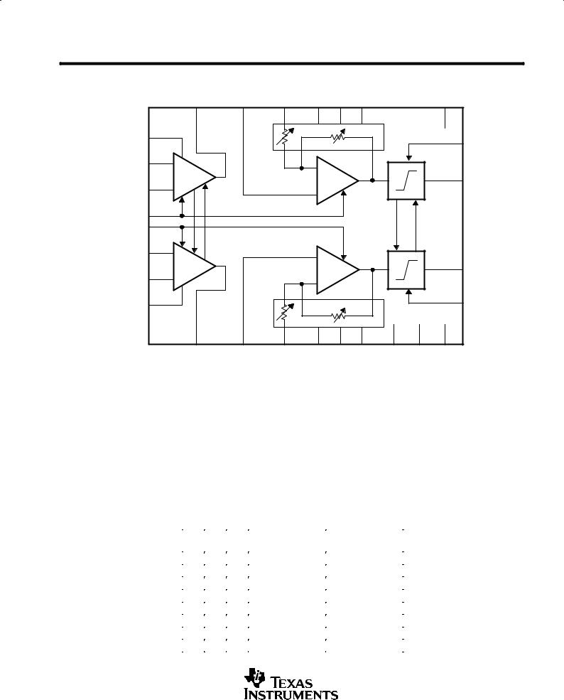
description
The THS7001 (single) and THS7002 (dual) are high-speed programmable-gain amplifiers, ideal for applications where load impedance can often vary. Each channel on this device consists of a separate low-noise input preamp and a programmable gain amplifier (PGA). The preamp is a voltage-feedback amplifier offering a low 1.7-nV/√ Hz voltage noise with a 100-MHz (±3 dB) bandwidth. The output pin of the preamp is accessible so that filters can be easily added to the amplifier.
The 3-bit digitally-controlled PGA provides a ±22-dB to 20-dB attenuation/gain range with a 6-dB step resolution. In addition, the PGA provides both high and low output clamp protection to prevent the output signal from swinging outside the common-mode input range of an analog-to-digital converter. The PGA provides a wide 70-MHz (±3 dB) bandwidth, which remains relatively constant over the entire gain/attenuation range. Independent shutdown control is also provided for power conservation and multiplexing. These devices operate over a wide ±4.5-V to ±16-V supply voltage range.
|
PREAMP |
|
|
|
|
|
|
|
OUT |
PGA IN± |
G0 |
G1 |
G2 |
|
|
PREAMP VCC+ |
|
|
|
|
|
|
CLAMP+ (VH) |
|
|
|
|
|
|
|
|
PREAMP IN± |
_ |
|
_ |
|
|
|
|
|
|
|
|
|
|
||
|
Preamp |
|
|
|
|
|
PGA OUT |
|
|
|
|
|
|
|
|
PREAMP IN+ |
+ |
|
+ |
|
|
|
|
|
|
|
|
|
|
|
|
PREAMP VCC± |
|
|
|
|
|
|
CLAMP± (V ) |
|
|
|
|
|
|
|
L |
|
SHDN |
PGA REF |
|
|
PGA |
PGA |
GND |
|
|
|
|
|
VCC+ |
VCC± |
|
Figure 1. THS7001 Block Diagram
CAUTION: The THS7001 and THS7002 provides ESD protection circuitry. However, permanent damage can still occur if this device is subjected to high-energy electrostatic discharges. Proper ESD precautions are recommended to avoid any performance degradation or loss of functionality.
Please be aware that an important notice concerning availability, standard warranty, and use in critical applications of Texas Instruments semiconductor products and disclaimers thereto appears at the end of this data sheet.
PowerPAD is a trademark of Texas Instruments Incorporated.
PRODUCTION DATA information is current as of publication date. Products conform to specifications per the terms of Texas Instruments standard warranty. Production processing does not necessarily include testing of all parameters.
Copyright 1999, Texas Instruments Incorporated
POST OFFICE BOX 655303 •DALLAS, TEXAS 75265 |
1 |

THS7001, THS7002
70-MHz PROGRAMMABLE-GAIN AMPLIFIERS
SLOS214B ± OCTOBER 1998 ± REVISED AUGUST 1999
THS7001
PWP PACKAGE
(TOP VIEW)
GND |
|
|
|
1 |
20 |
|
|
G0 |
|
|
|
|
|
|
|||||
VREFPGA |
|
|
2 |
19 |
|
|
G1 |
||
|
|
|
|
|
|||||
|
|
|
|
||||||
±VINPGA |
|
|
|
3 |
18 |
|
|
G2 |
|
|
4 |
17 |
|
|
|||||
VOUTPre-AMP |
|
|
|
|
|
SHDN |
|||
|
|
|
|
||||||
±VINPre-Amp |
|
|
|
5 |
16 |
|
|
VOUTPGA |
|
|
|
|
|
|
|||||
+VINPre-Amp |
|
|
|
6 |
15 |
|
|
VLNegative Clamp |
|
|
|
|
|
|
|||||
VCC±Pre-Amp |
|
|
|
7 |
14 |
|
|
VCC±PGA |
|
|
|
|
|
|
|||||
VCC+Pre-Amp |
|
|
|
8 |
13 |
|
|
VCC+PGA |
|
|
|
|
|
|
|||||
Spare/NC |
|
|
|
9 |
12 |
|
|
VHPositive Clamp |
|
|
|
|
|
||||||
Spare/NC |
|
|
|
10 |
11 |
|
|
Spare/NC |
|
|
|
|
|
|
|
|
|
|
|
|
|
|
|
|
|
THS7002 |
|
|
|
|
|
|
|
|
PWP PACKAGE |
|
|
|
|
|
|
|
|
|
|
(TOP VIEW) |
|
|
|
|
|
|
|
|
|
|
|
|
|
GND-A |
|
|
|
1 |
28 |
|
|
G0-A |
|
|
|
|
|
||||||
PGA-A REF |
|
|
|
2 |
27 |
|
|
G1-A |
|
|
|
|
|
||||||
PGA-A IN± |
|
|
|
3 |
26 |
|
|
G2-A |
|
|
|
|
4 |
25 |
|
|
|||
PREAMP OUT A |
|
|
|
|
|
SHDN±A |
|||
PREAMP-A IN± |
|
|
|
5 |
24 |
|
|
PGA-A OUT |
|
|
|
|
|
||||||
PREAMP-A IN+ |
|
|
|
6 |
23 |
|
|
CLAMP± (VL) |
|
|
|
|
|
||||||
|
|
|
|
||||||
PREAMP VCC± |
|
|
|
7 |
22 |
|
|
PGA VCC± |
|
|
|
|
|
||||||
PREAMP VCC+ |
|
|
|
8 |
21 |
|
|
PGA VCC+ |
|
|
|
|
|
||||||
PREAMP-B IN+ |
|
|
|
9 |
20 |
|
|
CLAMP+ (VH) |
|
|
|
|
|
||||||
PREAMP-B IN± |
|
|
|
10 |
19 |
|
|
PGA-B OUT |
|
PREAMP OUT B |
|
|
|
11 |
18 |
|
|
SHDN±B |
|
|
|
|
|
|
|||||
PGA-B IN± |
|
|
|
12 |
17 |
|
|
G2-B |
|
|
|
|
|
|
|||||
|
|
|
|
|
|||||
PGA-B REF |
|
|
|
13 |
16 |
|
|
G1-B |
|
|
|
|
|
|
|||||
GND-B |
|
|
|
14 |
15 |
|
|
G0-B |
|
|
|
|
|
|
|||||
|
|
|
|
|
|
|
|
|
|
AVAILABLE OPTIONS
|
NUMBER OF |
PACKAGED DEVICES |
EVALUATION |
|
TA |
|
|||
PowerPAD PLASTIC TSSOP |
||||
CHANNELS |
MODULE |
|||
|
|
(PWP) |
|
|
|
|
|
|
|
0°C to 70°C |
1 |
THS7001CPWP |
THS7001EVM |
|
|
|
|
||
2 |
THS7002CPWP |
THS7002EVM |
||
|
||||
|
|
|
|
|
±40°C to 85°C |
1 |
THS7001IPWP |
Ð |
|
|
|
|
||
2 |
THS7002IPWP |
Ð |
||
|
2 |
POST OFFICE BOX 655303 •DALLAS, TEXAS 75265 |
THS7001, THS7002
70-MHz PROGRAMMABLE-GAIN AMPLIFIERS
SLOS214B ± OCTOBER 1998 ± REVISED AUGUST 1999
block diagram
|
PREAMP |
|
PGA±A |
|
|
|
|
|
PGA±A |
|
OUT A |
PGA±A REF |
IN± |
G0A |
G1A |
G2A |
|
|
GND |
PREAMP VCC+ |
|
|
|
|
|
|
|
|
CLAMP+ (VH) |
|
|
|
|
|
|
|
|
|
|
PREAMP A IN± |
_ |
|
|
_ |
|
|
|
|
|
|
|
|
|
|
|
|
|
||
|
Preamp |
|
|
|
|
|
|
|
PGA±A OUT |
|
|
|
|
|
|
|
|
|
|
PREAMP A IN+ |
+ |
|
|
+ |
|
|
|
|
|
|
|
|
|
|
|
|
|
|
|
SHDN±A |
|
|
|
|
|
|
|
|
|
SHDN±B |
|
|
|
|
|
|
|
|
|
PREAMP B IN+ |
+ |
|
|
+ |
|
|
|
|
|
|
Preamp |
|
|
|
|
|
|
|
|
|
|
|
|
|
|
|
|
PGA±B OUT |
|
|
_ |
|
|
|
|
|
|
|
|
PREAMP B IN± |
|
|
_ |
|
|
|
|
|
|
|
|
|
|
|
|
|
|
||
PREAMP VCC± |
|
|
|
|
|
|
|
|
CLAMP± (VL) |
|
PREAMP |
PGA±B REF |
PGA±B |
G0B |
G1B |
G2B |
PGA |
PGA |
PGA±B |
|
OUT B |
|
IN± |
|
|
|
VCC+ |
VCC± |
GND |
Figure 2. THS7002 Dual Channel PGA
input preamp
To achieve the minimum input equivalent noise required for very small input signals, the input preamp is configured as a classic voltage feedback amplifier with a minimum gain of 2 or ±1. The output of the preamp is accessible, allowing for adjustment of gain using external resistors and for external filtering between the preamp and the PGA.
programmable gain amplifier (PGA)
The PGA is an inverting, programmable gain amplifier. The gain is digitally programmable using three control bits (TTL-compatible terminals) that are encoded to provide eight distinct levels of gain/attenuation. Nominal gain/attenuation is shown in Table 1.
Table 1. Nominal Gain/Attenuation
|
G2 |
G1 |
G0 |
PGA GAIN |
PGA GAIN |
|
|
(dB) |
(V/V) |
|
|||
|
|
|
|
|
||
|
|
|
|
|
|
|
|
0 |
0 |
0 |
±22 |
0.08 |
|
|
|
|
|
|
|
|
|
0 |
0 |
1 |
±16 |
0.16 |
|
|
|
|
|
|
|
|
|
0 |
1 |
0 |
±10 |
0.32 |
|
|
|
|
|
|
|
|
|
0 |
1 |
1 |
±4 |
0.63 |
|
|
|
|
|
|
|
|
|
1 |
0 |
0 |
2 |
1.26 |
|
|
|
|
|
|
|
|
|
1 |
0 |
1 |
8 |
2.52 |
|
|
|
|
|
|
|
|
|
1 |
1 |
0 |
14 |
5.01 |
|
|
|
|
|
|
|
|
|
1 |
1 |
1 |
20 |
10.0 |
|
|
|
|
|
|
|
|
|
|
|
|
|
|
|
POST OFFICE BOX 655303 •DALLAS, TEXAS 75265 |
3 |

THS7001, THS7002
70-MHz PROGRAMMABLE-GAIN AMPLIFIERS
SLOS214B ± OCTOBER 1998 ± REVISED AUGUST 1999
output clamping
Output clamping for both upper (VH) and lower (VL) levels for the PGAs is provided. There is only one terminal for the positive output clamp and one for the negative output clamp for both channels.
shutdown control
The SHDN terminals allow for powering down the internal circuitry for power conservation or for multiplexing. Separate shutdown controls are available for each channel. The control levels are TTL compatible.
absolute maximum ratings over operating free-air temperature (see Notes 1 and 2)²
Supply voltage, VCC . . . . . . . . . . . . . . . . . . . . . . . . . . . . . . . . . . . . . . . . . . . . . . . . . . . . . . . . . . . . . . |
. . . . . . ±16.5 V |
Input voltage, VI . . . . . . . . . . . . . . . . . . . . . . . . . . . . . . . . . . . . . . . . . . . . . . . . . . . . . . . . . . . . . . . . . . |
. . . . . . . . ±VCC |
Output current, IO (preamp) (see Note 1) . . . . . . . . . . . . . . . . . . . . . . . . . . . . . . . . . . . . . . . . . . . . |
. . . . . . 150 mA |
IO (PGA) (see Note 1) . . . . . . . . . . . . . . . . . . . . . . . . . . . . . . . . . . . . . . . . . . . . . . . |
. . . . . . . 85 mA |
Differential input voltage, VID . . . . . . . . . . . . . . . . . . . . . . . . . . . . . . . . . . . . . . . . . . . . . . . . . . . . . . . |
. . . . . . . . . ±4 V |
Total continuous power dissipation at (or below) TA = 25°C (see Note 2): THS7001 . . . . . . . |
. . . . . . . 3.83 W |
THS7002 . . . . . . . |
. . . . . . . 4.48 W |
Maximum junction temperature, TJ . . . . . . . . . . . . . . . . . . . . . . . . . . . . . . . . . . . . . . . . . . . . . . . . . |
. . . . . . . 150°C |
Operating free-air temperature, TA:C-suffix . . . . . . . . . . . . . . . . . . . . . . . . . . . . . . . . . . . . . . . . . . . |
. . 0°C to 70°C |
I-suffix . . . . . . . . . . . . . . . . . . . . . . . . . . . . . . . . . . . . . . . . . . . . |
±40°C to 85°C |
Storage temperature, Tstg . . . . . . . . . . . . . . . . . . . . . . . . . . . . . . . . . . . . . . . . . . . . . . . . . . . . . . . . |
±65°C to 125°C |
Lead temperature 1,6 mm (1/16 inch) from case for 10 seconds . . . . . . . . . . . . . . . . . . . . . . . . |
. . . . . . . 300°C |
²Stresses beyond those listed under ªabsolute maximum ratingsº may cause permanent damage to the device. These are stress ratings only, and functional operation of the device at these or any other conditions beyond those indicated under ªrecommended operating conditionsº is not
implied. Exposure to absolute-maximum-rated conditions for extended periods may affect device reliability.
NOTES: 1. The THS7001 and THS7002 incorporates a PowerPAD on the underside of the chip. The PowerPAD acts as a heatsink and must be connected to a thermal dissipation plane for proper power dissipation. Failure to do so can result in exceeding the maximum junction temperature, which could permanently damage the device. See the Thermal Information section of this document for more information about PowerPAD technology.
2.For operation above TA = 25°C, derate the THS7001 linearly to 2 W at the rate of 30.6 mW/°C and derate the THS7002 linearly to
2.33W at the rate of 35.9 mW/°C.
recommended operating conditions
|
|
MIN NOM |
MAX |
UNIT |
|
|
|
|
|
|
|
Preamp supply voltage, VCC+ and VCC± |
Split supply |
±4.5 |
±16 |
V |
|
PGA supply voltage, VCC+ and VCC± |
Split supply |
±4.5³ |
±16 |
V |
|
Operating free-air temperature, TA |
C-suffix |
0 |
70 |
°C |
|
|
|
|
|
||
I-suffix |
±40 |
85 |
°C |
||
|
|||||
|
|
|
|
|
³ PGA minimum supply voltage must be less than or equal to preamp supply voltage.
4 |
POST OFFICE BOX 655303 •DALLAS, TEXAS 75265 |

THS7001, THS7002
70-MHz PROGRAMMABLE-GAIN AMPLIFIERS
SLOS214B ± OCTOBER 1998 ± REVISED AUGUST 1999
preamp electrical characteristics, G = 2, TA = 25°C, RL = 150 Ω, (unless otherwise noted)
|
PARAMETER |
|
TEST CONDITIONS² |
MIN |
TYP |
MAX |
UNIT |
|
VCC |
Supply voltage operating range |
Split supply |
|
±4.5 |
|
±16.5 |
V |
|
|
|
RL = 1 kΩ |
VCC = ±5 V |
±3.6 |
±3.8 |
|
|
|
VOM |
Maximum output voltage swing |
VCC = ±15 V |
±13 |
±13.6 |
|
V |
||
|
|
|
||||||
RL = 150 Ω |
VCC = ±5 V |
±3.5 |
±3.7 |
|
||||
|
|
|
|
|||||
|
|
RL = 250 Ω |
VCC = ±15 V |
±11 |
±12.6 |
|
|
|
VIO |
Input offset voltage |
VCC |
= ±5 V or ±15 V |
TA = 25°C |
|
1 |
5 |
mV |
TA = full range |
|
|
7 |
|||||
|
|
|
|
|
|
|
||
|
Input offset voltage drift |
|
|
|
|
10 |
|
µV/°C |
|
|
|
|
|
|
|
|
|
VICR |
Common-mode input voltage range |
VCC = ±5 V |
|
±3.8 |
±4.2 |
|
V |
|
VCC = ±15 V |
|
±13.8 |
±14 |
|
||||
|
|
|
|
|
||||
IO |
Output current (see Note 3) |
RL = 20 Ω |
VCC = ±5 V |
40 |
70 |
|
mA |
|
VCC = ±15 V |
60 |
95 |
|
|||||
|
|
|
|
|
|
|||
IOC |
Short-circuit output current (see Note 3) |
VCC = ±15 V |
|
|
120 |
|
mA |
|
IIB |
Input bias current |
VCC |
= ±5 V or ±15 V |
TA = 25°C |
|
2.5 |
6 |
µA |
TA = full range |
|
|
8 |
|||||
|
|
|
|
|
|
|
||
IIO |
Input offset current |
VCC |
= ±5 V or ±15 V |
TA = 25°C |
|
30 |
175 |
nA |
TA = full range |
|
|
400 |
|||||
|
|
|
|
|
|
|
||
|
Input offset current drift |
|
|
|
|
0.3 |
|
nA/°C |
|
|
|
|
|
|
|
|
|
|
|
V |
= ±5 V, |
TA = 25°C |
80 |
89 |
|
|
|
|
CC |
|
|
|
|
|
|
|
|
VIC = ±2.5 V |
T = full range |
78 |
|
|
|
|
CMRR |
Common-mode rejection ratio |
|
|
A |
|
|
|
dB |
V |
= ±15 V, |
TA = 25°C |
80 |
88 |
|
|||
|
|
|
|
|||||
|
|
CC |
|
|
|
|
|
|
|
|
VIC = ±12 V |
T = full range |
78 |
|
|
|
|
|
|
|
|
A |
|
|
|
|
PSRR |
Power supply rejection ratio |
VCC |
= ±5 V or ±15 V |
TA = 25°C |
85 |
100 |
|
dB |
TA = full range |
80 |
|
|
|||||
|
|
|
|
|
|
|
||
RI |
Input resistance |
|
|
|
|
1 |
|
MΩ |
CI |
Input capacitance |
|
|
|
|
1.5 |
|
pF |
RO |
Output resistance |
Open loop |
|
|
13 |
|
Ω |
|
|
|
VCC |
= ±5 V |
TA = 25°C |
|
5.5 |
7 |
|
ICC |
Quiescent current (per channel) |
TA = full range |
|
|
8 |
mA |
||
|
|
|
|
|||||
VCC |
= ±15 V |
TA = 25°C |
|
7 |
8 |
|||
|
|
|
|
|||||
|
|
TA = full range |
|
|
9 |
|
||
|
|
|
|
|
|
|
||
² Full range for the THS7001/02C is 0°C to 70°C. Full range for the THS7001/022I is ± 40°C to 85°C.
NOTE 3: A heatsink may be required to keep the junction temperature below absolute maximum when an output is heavily loaded or shorted. (See absolute maximum ratings and thermal information section.)
POST OFFICE BOX 655303 •DALLAS, TEXAS 75265 |
5 |
25°C, RL = 150 Ω, (unless otherwise noted)
|
PARAMETER |
TEST CONDITIONS² |
MIN |
TYP |
MAX |
UNIT |
|||
|
|
|
VO = ±2 V, |
|
65 |
|
|
|
|
|
|
|
VCC = ±5 V |
|
|
|
|
|
|
SR |
Slew rate (see Note 4) |
G = ±1 |
|
|
|
V/µs |
|||
VO = ±10 V, |
|
85 |
|
||||||
|
|
|
|
|
|
|
|
||
|
|
|
VCC = ±15 V |
|
|
|
|
|
|
|
|
|
|
|
|
|
|
|
|
|
Settling time to 0.1% |
|
VCC = ±5 V |
|
85 |
|
|
|
|
ts |
G = ±1, |
VCC = ±15 V |
|
70 |
|
ns |
|||
|
|
|
|||||||
Settling time to 0.01% |
5 V Step |
VCC = ±5 V |
|
95 |
|
||||
|
|
|
|
|
|
||||
|
|
VCC = ±15 V |
|
90 |
|
|
|
|
|
|
|
|
|
|
|
|
|
||
THD |
Total harmonic distortion |
VCC = ±15 V, |
fc = 1 MHz, |
|
± 88 |
|
dBc |
||
VO(PP) = 2V |
RL = 250 Ω |
|
|
||||||
|
|
|
|
|
|
|
|
||
Vn |
Input noise voltage |
VCC = ±5 V or ±15 V, |
f = 10 kHz |
|
1.7 |
|
nV/√ |
|
|
|
|
Hz |
|
||||||
In |
Input noise current |
VCC = ±5 V or ±15 V, |
f = 10 kHz |
|
0.9 |
|
pA/√ |
|
|
|
|
Hz |
|
||||||
BW |
Small-signal bandwidth (±3 dB) |
VO(PP) = 0.4V, |
VCC = ±5 V |
|
85 |
|
MHz |
||
G = 2 |
VCC = ±15 V |
|
100 |
|
|||||
|
|
|
|
|
|
|
|||
|
Bandwidth for 0.1 dB flatness |
VO(PP) = 0.4V, |
VCC = ±5 V |
|
35 |
|
MHz |
||
|
G = 2 |
VCC = ±15 V |
|
45 |
|
||||
|
|
|
|
|
|
|
|||
|
Full power bandwidth (see Note 5) |
VCC = ±5 V, |
VO = 5 VO(PP) |
|
4.1 |
|
MHz |
||
|
VCC = ±15 V, |
VO = 20 VO(PP) |
|
1.4 |
|
||||
|
|
|
|
|
|
|
|||
AD |
Differential gain error |
G = 2, 100 IRE, |
VCC = ±5 V |
|
0.02% |
|
|
|
|
NTSC |
VCC = ±15 V |
|
0.02% |
|
|
|
|
||
|
|
|
|
|
|
|
|||
φD |
Differential phase error |
G = 2, 100 IRE, |
VCC = ±5 V |
|
0.01° |
|
|
|
|
NTSC |
VCC = ±15 V |
|
0.01° |
|
|
|
|
||
|
|
|
|
|
|
|
|||
|
|
VCC = ±5 V, |
TA = 25°C |
85 |
89 |
|
|
|
|
|
|
VO = ±2.5 V, |
|
|
|
|
|
|
|
|
|
TA = full range |
83 |
|
|
|
|
|
|
|
Open loop gain |
RL = 1 kΩ |
|
|
dB |
||||
|
|
VCC = ±15 V, |
TA = 25°C |
86 |
91 |
|
|
|
|
|
|
VO = ±10 V, RL = 1 kΩ |
T = full range |
84 |
|
|
|
|
|
|
|
|
A |
|
|
|
|
|
|
|
Channel-to-channel crosstalk (THS7002) |
VCC = ±5 V or ±15 V, |
f = 1 MHz |
|
±85 |
|
dB |
||
² Full range for the THS7001/02C is 0°C to 70°C. Full range for the THS7001/02I is ± 40°C to 85°C. NOTES: 4. Slew rate is measured from an output level range of 25% to 75%.
5. Full power bandwidth = slew rate/2π V(PP).
shutdown electrical characteristics
|
PARAMETER |
|
|
|
TEST CONDITIONS |
MIN |
TYP |
MAX |
UNIT |
|
|
|
|
|
|
|
|
|
|
|
|
|
Standby current, disabled |
Preamp |
|
|
|
VCC = ±5 V |
|
0.2 |
0.3 |
|
ICC(standby) |
VI(SHDN) = 2.5 V |
VCC = ±15 V |
|
0.65 |
0.8 |
mA |
||||
(per channel) |
|
|
||||||||
|
PGA |
|
|
|
VCC = ±5 V or ±15 V |
|
0.8 |
1.2 |
|
|
|
|
|
|
|
|
|
||||
VIH(SHDN) |
Shutdown voltage for power up |
VCC = ±5 V or ±15 V, |
Relative to GND |
|
|
0.8 |
V |
|||
VIL(SHDN) |
Shutdown voltage for power down |
2 |
|
|
V |
|||||
|
|
|
|
|
|
|||||
IIH(SHDN) |
Shutdown input current high |
|
VCC = ±5 V or ±15 V, |
VI(SHDN) = 5 V |
|
300 |
400 |
µA |
||
IIL(SHDN) |
Shutdown input current low |
|
VI(SHDN) = 0.5 V |
|
25 |
50 |
µA |
|||
|
|
|
|
|
||||||
t |
Disable time² |
|
V |
CC |
= ±5 V or ±15 V, |
Preamp and PGA |
|
100 |
|
ns |
dis |
|
|
|
|
|
|
|
|
|
|
t |
Enable time² |
|
V |
CC |
= ±5 V or ±15 V, |
Preamp and PGA |
|
1.5 |
|
µs |
en |
|
|
|
|
|
|
|
|
|
|
²Disable time and enable time are defined as the interval between application of the logic signal to SHDN and the point at which the supply current has reached half its final value.
6 |
POST OFFICE BOX 655303 •DALLAS, TEXAS 75265 |
THS7001, THS7002
70-MHz PROGRAMMABLE-GAIN AMPLIFIERS
SLOS214B ± OCTOBER 1998 ± REVISED AUGUST 1999
PGA electrical characteristics, TA = 25°C, Gain = 2 dB, RL = 1 kΩ, (unless otherwise noted)
|
PARAMETER |
TEST CONDITIONS² |
MIN |
TYP |
MAX |
UNIT |
|
VCC |
Supply voltage range |
Split supply |
|
±4.5³ |
|
±16.5 |
V |
VOM |
Maximum output voltage swing |
RL = 1 kΩ |
VCC = ±5 V |
±3.6 |
±4.1 |
|
V |
VCC = ±15 V |
±13.2 |
±13.8 |
|
||||
|
|
|
|
|
|||
VIO |
Input offset voltage |
VCC = ±5 V or ±15 V |
TA = 25°C |
|
2 |
9 |
mV |
TA = full range |
|
|
11 |
||||
|
|
|
|
|
|
||
|
Input offset voltage drift |
|
|
|
10 |
|
µV/°C |
|
Reference input voltage range |
VCC = ±5 V |
|
±3.8 |
±4.0 |
|
V |
|
VCC = ±15 V |
|
±13.5 |
±13.8 |
|
||
|
|
|
|
|
|||
IIB |
Input bias current (reference terminal) |
VCC = ±5 V or ±15 V |
TA = 25°C |
|
1 |
2 |
µA |
TA = full range |
|
|
3 |
||||
|
|
|
|
|
|
||
IO |
Output current |
RL = 20 Ω |
VCC = ±5 V |
30 |
50 |
|
mA |
IOS |
Short-circuit output current |
|
|
|
80 |
|
mA |
PSRR |
Power supply rejection ratio |
VCC = ±5 V or ±15 V |
TA = 25°C |
75 |
82 |
|
dB |
TA = full range |
72 |
|
|
||||
|
|
|
|
|
|
||
RI |
Input resistance |
Gain = 20 dB |
|
|
0.27 |
|
kΩ |
|
|
|
|
|
|||
Gain = ±22 dB |
|
|
3 |
|
|||
|
|
|
|
|
|
||
|
|
|
|
|
|
|
|
RO |
Output resistance |
Open loop |
|
|
20 |
|
Ω |
|
|
VCC = ±5 V |
TA = 25°C |
|
4.8 |
6 |
|
ICC |
Quiescent supply current (per channel) |
TA = full range |
|
|
7 |
mA |
|
|
|
|
|||||
VCC = ±15 V |
TA = 25°C |
|
5 |
7 |
|||
|
|
|
|
||||
|
|
TA = full range |
|
|
8 |
|
|
|
|
|
|
|
|
||
² Full range for the THS7001/02C is 0°C to 70°C. Full range for the THS7001/02I is ± 40°C to 85°C. ³ PGA minimum supply voltage must be less than or equal to preamp supply voltage.
output limiting characteristics
PARAMETER |
|
|
TEST CONDITIONS² |
|
MIN |
TYP |
MAX |
UNIT |
|||
|
VCC = ±15 V, |
VH = 10 V, |
|
TA = 25°C |
|
±250 |
±300 |
|
|||
|
VI = ±10 V, |
VL = ±10 V, |
|
|
|
|
|
|
|||
|
|
TA = full range |
|
|
±350 |
|
|||||
Clamp accuracy |
Gain = 2 dB |
|
|
|
|
|
|
mV |
|||
VCC = ±5 V, |
VH = 2 V, |
|
TA = 25°C |
|
±50 |
±80 |
|||||
|
|
|
|
||||||||
|
VI = ±2.5 V, |
VL = ±2 V, |
|
|
|
|
|
|
|||
|
|
TA = full range |
|
|
±100 |
|
|||||
|
Gain = 2 dB |
|
|
|
|
|
|
|
|||
|
VCC = ±15 V, |
VH = 10 V, |
VL = ±10 V, |
|
0.5% |
|
|
||||
|
VI = ±10 V, |
tr and tf = 1 ns |
|
|
|
|
|||||
Clamp overshoot |
|
|
|
|
|
||||||
VCC = ±5 V, |
VH = 2 V, |
VL = ±2 V, |
|
0.3% |
|
|
|||||
|
|
|
|
||||||||
|
VI = ±2.5 V, |
tr and tf = 1 ns |
|
|
|
|
|||||
|
|
|
|
|
|
||||||
|
VCC = ±15 V, |
VH = 10 V, |
VL = ±10 V, |
|
7 |
|
|
||||
|
VI = ±10 V |
|
|
|
|
|
|
|
|
||
Overdrive recovery time |
|
|
|
|
|
|
|
|
ns |
||
VCC = ±5 V, |
VH = 2 V, |
VL = 2 V, |
|
6 |
|
||||||
|
|
|
|
||||||||
|
VI = ±2.5 V |
|
|
|
|
|
|
|
|
||
|
|
|
|
|
|
|
|
|
|
||
|
V |
= 3.3 V, |
V |
|
= 3.3 V, |
|
TA = 25°C |
|
1 |
5 |
|
Clamp input bias current |
|
O |
|
L |
|
|
|
|
|
|
µA |
|
|
|
|
T = full range |
|
|
8 |
||||
|
VH = 3.3 V |
|
|
|
|
|
|
|
|||
|
|
|
|
|
|
|
A |
|
|
|
|
² Full range for the THS7002C is 0°C to 70°C. Full range for the THS7002I is ± 40°C to 85°C.
POST OFFICE BOX 655303 •DALLAS, TEXAS 75265 |
7 |
THS7001, THS7002
70-MHz PROGRAMMABLE-GAIN AMPLIFIERS
SLOS214B ± OCTOBER 1998 ± REVISED AUGUST 1999
PGA electrical characteristics, TA = 25°C, Gain = 2 dB, RL = 1 kΩ, (unless otherwise noted)
(continued)
digital gain characteristics
|
PARAMETER |
|
|
TEST CONDITIONS |
MIN TYP |
MAX |
UNIT |
|
|
|
|
|
|
|
|
VIH |
High-level input voltage |
Relative to GND |
2 |
|
V |
||
VIL |
Low-level input voltage |
|
0.8 |
V |
|||
|
|
|
|
||||
IIH |
High-level input current |
VIH = 5 V |
20 |
100 |
nA |
||
IIL |
Low-level input current (sink current) |
VIL = 0.5 V |
0.9 |
2 |
µA |
||
t |
Gain-change delay time² |
V |
CC |
= ±5 V or ±15 V |
2 |
|
µs |
d |
|
|
|
|
|
|
|
² Gain-change delay time is the time needed to reach 90% of its final gain value.
PGA operating characteristics, TA = 25°C, Gain = 2 dB, RL = 1 kΩ, (unless otherwise noted)
|
PARAMETER |
|
TEST CONDITIONS² |
|
MIN |
TYP |
MAX |
UNIT |
|||
SR |
Slew rate (see Note 4) |
VCC = ±5 V, |
VO = ±2.5 V |
|
160 |
|
V/µs |
||||
VCC = ±15 V, |
VO = ±10 V |
|
175 |
|
|||||||
|
|
|
|
|
|
|
|||||
ts |
Settling time to 0.1% |
5 V Step |
|
VCC = ±15 V |
|
125 |
|
ns |
|||
|
VCC = ±5 V |
|
120 |
|
|||||||
|
|
|
|
|
|
|
|
|
|||
THD |
Total harmonic distortion |
VCC = ±15 V, |
VO(PP)= 2 V, |
|
± 69 |
|
dBc |
||||
fc = 1 MHz, |
|
Gain = 8 dB |
|
|
|||||||
|
|
|
|
|
|
|
|
|
|||
|
|
Gain = 20 dB, |
VCC = ±15 V |
|
65 |
|
|
|
|
||
|
|
VO(PP) = 0.4 V |
V |
= ±5 V |
|
60 |
|
|
|
|
|
|
|
|
|
CC |
|
|
|
|
|
|
|
BW |
Small-signal bandwidth (±3 dB) |
Gain = 2 dB, |
VCC = ±15 V |
|
75 |
|
MHz |
||||
VO(PP) = 0.4 V |
V |
= ±5 V |
|
70 |
|
||||||
|
|
|
|
|
|
|
|||||
|
|
|
|
CC |
|
|
|
|
|
|
|
|
|
Gain = ±22 dB, |
VCC = ±15 V |
|
80 |
|
|
|
|
||
|
|
VO(PP) = 0.4 V |
V |
= ±5 V |
|
70 |
|
|
|
|
|
|
|
|
|
CC |
|
|
|
|
|
|
|
|
Bandwidth for 0.1 dB flatness |
Gain = 2 dB, |
VCC = ±15 V |
|
20 |
|
MHz |
||||
|
VO(PP) = 0.4 V |
V |
= ±5 V |
|
18 |
|
|||||
|
|
|
|
|
|
|
|||||
|
|
|
|
CC |
|
|
|
|
|
|
|
|
Full power bandwidth (see Note 5) |
VO(PP) = 5 V, |
VCC = ±5 V |
|
10 |
|
MHz |
||||
|
VO(PP) = 20 V, |
VCC = ±15 V |
|
2.8 |
|
||||||
|
|
|
|
|
|
|
|||||
AD |
Differential gain error |
G = 8 dB, |
100 IRE, |
VCC = ±5 V |
|
0.04% |
|
|
|
|
|
NTSC, |
RL = 150 Ω |
VCC = ±15 V |
|
0.04% |
|
|
|
|
|||
|
|
|
|
|
|
|
|||||
φD |
Differential phase error |
G = 8 dB, |
±100 IRE, |
VCC = ±15 V |
|
0.07 |
|
° |
|
|
|
NTSC, |
RL = 150 Ω |
VCC = ±5 V |
|
0.09 |
|
|
|
||||
|
|
|
|
|
|
|
|||||
|
Gain accuracy (see Note 6) |
Gain = ±22 dB to 20 dB, |
TA = 25°C |
±7.5% |
0% |
7.5% |
|
|
|
||
|
All 8 steps, |
|
|
|
|
|
|
|
|
|
|
|
|
TA = full range |
±8.5% |
|
8.5% |
|
|
|
|||
|
|
V = ±5 V or ±15 V |
|
|
|
|
|||||
|
|
CC |
|
|
|
|
|
|
|
|
|
|
Channel-to-channel gain accuracy |
Gain = ±22 dB to 20 dB, |
TA = 25°C |
±5.5% |
0% |
5.5% |
|
|
|
||
|
All 8 steps, |
|
|
|
|
||||||
|
(THS7002 only) (see Note 7) |
|
TA = full range |
±6.5% |
|
6.5% |
|
|
|
||
|
V = ±5 V or ±15 V |
|
|
|
|
||||||
|
|
CC |
|
|
|
|
|
|
|
|
|
Vn |
Input referred noise voltage |
VCC = ±5 V or ±15 V, |
Gain = 20 dB |
|
10 |
|
|
|
|
||
|
|
nV/√ Hz |
|||||||||
f = 10 kHz |
|
Gain = ±22 dB |
|
500 |
|
||||||
|
|
|
|
|
|
|
|
||||
|
|
|
|
|
|
|
|
|
|
|
|
|
PGA channel-to-channel crosstalk |
VCC = ±5 V or ±15 V, |
f = 1 MHz |
|
±77 |
|
dB |
||||
|
(THS7002 only) |
|
|
||||||||
|
|
|
|
|
|
|
|
|
|
|
|
|
|
|
|
|
|
|
|
|
|
|
|
² Full range for the THS7001/02C is 0°C to 70°C. Full range for the THS7001/02I is ± 40°C to 85°C. NOTES: 4. Slew rate is measured from an output level range of 25% to 75%.
5.Full power bandwidth = slew rate/2π VPEAK
6.Specified as ±100 × (output voltage ± (input voltage × gain))/(input voltage × gain)
7.Specified as 100 × (output voltage B± output voltage A)/output voltage A
8 |
POST OFFICE BOX 655303 •DALLAS, TEXAS 75265 |

THS7001, THS7002
70-MHz PROGRAMMABLE-GAIN AMPLIFIERS
|
SLOS214B ± OCTOBER 1998 ± REVISED AUGUST 1999 |
|
|
|
|
|
TYPICAL CHARACTERISTICS |
|
INPUT OFFSET VOLTAGE |
STANDBY SUPPLY CURRENT |
QUIESCENT SUPPLY CURRENT |
vs |
vs |
vs |
FREE-AIR TEMPERATURE |
FREE-AIR TEMPERATURE |
FREE-AIR TEMPERATURE |
|
3.5 |
|
|
|
|
|
|
|
|
2 |
|
|
|
|
|
|
|
|
9 |
|
|
|
|
|
|
|
|
|
|
|
|
|
|
|
|
|
|
|
PGA ± ICC |
|
|
|
|
|
|
|
|
|
|
Per Channel |
|
||||
InputOffset Voltage ± mV |
3 |
|
|
|
|
|
|
|
Supply Current ± mA |
1.5 |
|
|
|
|
|
|
|
Supply± Current ± mA |
8 |
|
Preamp |
|
|
|
|
|
|
|
|
PGA |
|
|
|
|
|
|
|
|
Preamp ± I |
|
|
|
VCC = ±15 V |
|
|
|
|
|
|||||||
2.5 |
|
VCC = ±5 V |
|
|
|
|
|
|
|
|
|
CC |
|
|
|
|
|
|
|
|
|
|
|
||||
|
|
|
|
|
|
|
|
|
|
|
|
|
7 |
|
|
|
|
|
|
|
|
||||||
|
|
|
|
|
|
|
|
|
|
|
|
|
|
|
|
|
|
|
|
|
|
|
|
||||
2 |
|
|
|
|
PGA |
|
|
1 |
|
|
|
Preamp ± IEE |
|
|
|
Preamp |
|
|
|
|
|
|
|||||
|
|
|
|
|
VCC = ±15 V |
|
|
|
|
|
|
|
|
|
6 |
|
|
|
|
|
|
||||||
1.5 |
|
|
|
|
|
|
|
|
|
|
|
|
|
VCC = ±5 V |
|
|
|
|
|
|
|||||||
|
|
|
|
Preamp |
|
|
0.5 |
|
|
|
|
|
|
|
|
|
|
|
|
|
|
|
|
||||
|
|
|
|
|
|
|
|
|
|
|
|
|
|
5 |
|
|
|
|
|
|
|
|
|||||
1 |
|
Preamp |
|
VCC = ±15 V |
|
|
PGA ± I |
|
|
|
|
|
|
|
|
|
|
PGA |
|
|
|||||||
± |
|
VCC = ±5 V |
|
|
|
|
Standby |
|
EE |
|
|
|
|
|
CC |
|
|
|
|
|
|
|
|||||
|
|
|
|
|
|
0 |
|
|
|
|
|
|
|
|
|
|
|
V |
CC |
= ±15 V |
|
||||||
IO |
|
|
|
|
|
|
|
|
|
|
|
|
|
|
|
I |
4 |
|
PGA |
|
|
|
|
||||
V |
0.5 |
|
|
|
|
|
|
|
|
|
|
|
|
|
|
|
|
|
|
|
|
|
|
|
|||
|
|
|
|
|
|
|
|
|
|
|
|
|
|
|
|
|
|
|
|
VCC = ±5 V |
|
|
|
|
|
||
|
|
|
|
|
|
|
|
|
|
|
VCC = ±15 V |
|
|
|
|
|
|
|
|
|
|
|
|
||||
|
0 |
|
|
|
|
|
|
|
|
±0.5 |
|
|
|
|
|
|
|
|
|
|
|
|
|
|
|||
|
|
|
|
|
|
|
|
|
|
|
|
|
|
|
|
|
3 |
|
|
|
|
|
|
|
|
||
|
±40 |
±20 |
0 |
20 |
40 |
60 |
80 |
100 |
|
±40 |
±20 |
0 |
20 |
40 |
60 |
80 |
100 |
|
±40 |
±20 |
0 |
20 |
40 |
60 |
80 |
100 |
|
|
|
TA ± Free-AIR Temperature ± _C |
|
|
|
TA ± Free-Air Temperature ± _C |
|
|
|
TA ± Free-Air Temperature ± _C |
|
||||||||||||||||
|
|
|
|
Figure 3 |
|
|
|
|
|
|
|
Figure 4 |
|
|
|
|
|
|
Figure 5 |
|
|
|
|
||||
|
|
|
|
PSRR |
|
|
|
|
|
INPUT BIAS CURRENT |
|
||||||
|
|
|
|
vs |
|
|
|
|
|
|
|
vs |
|
|
|
|
|
dB± |
|
|
FREQUENCY |
|
|
|
|
FREE-AIR TEMPERATURE |
|
||||||||
120 |
|
|
|
|
|
|
|
|
3 |
|
|
|
|
|
|
|
|
|
|
|
|
|
|
|
|
|
|
|
|
|
|
|
|
||
Ratio |
100 |
|
|
Preamp - VCC + & VCC ± |
uA± |
2.5 |
|
|
Pre±Amp: VCC = ±15 V |
|
|||||||
|
|
|
|
|
|
|
|
|
|
||||||||
RejectionSupply-Power |
|
|
|
|
|
|
|
CurrentBiasInput±Iib |
|
|
|
||||||
80 |
|
|
|
|
|
|
|
2 |
|
|
Pre±Amp: VCC = ±5 V |
|
|
||||
|
|
|
|
|
|
|
|
|
|
|
|
|
|
|
|||
|
60 |
PGA - VCC + |
|
|
|
|
|
1.5 |
|
|
|
|
|
|
|
||
|
40 |
|
PGA - VCC ± |
|
|
|
|
1 |
PGA: VCC = ±15 V and ±5 V |
|
|
|
|||||
|
|
|
|
|
|
|
|
|
|
|
|
||||||
|
|
|
|
|
|
|
|
|
|
|
|
|
|
||||
± |
20 |
VCC = ±15 V & ±5 V |
|
|
|
|
|
0.5 |
|
|
|
|
|
|
|
||
PSRR |
|
|
|
|
|
|
|
|
|
|
|
|
|||||
|
|
|
|
|
|
|
|
|
|
|
|
|
|
||||
0 |
|
|
|
|
|
|
|
|
0 |
|
|
|
|
|
|
|
|
|
|
|
|
|
|
|
|
|
|
|
|
|
|
|
|
||
|
10 |
100 |
1k |
10k |
100k |
1M |
10M |
100M |
|
±40 |
±20 |
0 |
20 |
40 |
60 |
80 |
100 |
|
|
|
f ± Frequency ± Hz |
|
|
|
|
TA ± Free-Air Temperature ± _C |
|
||||||||
|
|
|
|
Figure 6 |
|
|
|
|
|
|
|
Figure 7 |
|
|
|
||
PREAMP INPUT COMMON-MODE |
|
VOLTAGE RANGE |
PREAMP OUTPUT VOLTAGE |
vs |
vs |
SUPPLY VOLTAGE |
SUPPLY VOLTAGE |
V |
15 |
|
|
|
|
|
14 |
|
TA = 25 _C |
|
|
|
|
||
+ ± |
|
|
|
|
|
||
Input Common-Mode Range ± |
13 |
|
|
|
|
| ± Output Voltage Swing ± V |
12 |
11 |
|
|
|
|
10 |
||
9 |
|
|
|
|
8 |
||
7 |
|
|
|
|
6 |
||
|
|
|
|
|
|
||
± |
5 |
|
|
|
|
O |
4 |
ICR |
|
|
|
|
|
|V |
|
V |
3 |
|
|
|
|
|
2 |
|
|
|
|
|
|
||
|
5 |
7 |
9 |
11 |
13 |
15 |
|
|
|
±VCC ± Supply Voltage ± V |
|
|
|||
Figure 9
|
TA = 25° C |
|
|
|
|
|
|
|
RL = 1 kΩ |
|
|
|
|
|
|
RL = 250 Ω |
|
5 |
7 |
9 |
11 |
13 |
15 |
|
± VCC ± Supply Voltage ± V |
|
|||
Figure 10
CLOSED-LOOP OUTPUT
IMPEDANCE vs
FREQUENCY
|
100 |
VCC = ±15 V & ±5 V |
|
|
|
|
|
|
|
|
|
± Ω |
|
V|(PP)= 2 V |
|
|
|
10 |
|
|
|
|
|
Impedance |
PGA: G = +20 dB |
|
|
|
|
|
|
|
|
||
1 |
|
PGA: G = ±22 dB |
|||
± Output |
|
||||
0.1 |
|
|
|
|
|
o |
|
|
|
|
|
Z |
|
|
|
|
|
|
|
Preamp: G = +2 |
|
|
|
|
0.01 |
|
|
|
|
|
100k |
1M |
10M |
100M |
500M |
|
|
f ± Frequency ± Hz |
|
|
|
Figure 8
|
|
|
PREAMP CMRR |
|
|
||
|
|
|
|
vs |
|
|
|
dB |
100 |
|
FREQUENCY |
|
|
||
|
|
|
|
|
|
||
Ratio ± |
|
|
|
|
|
|
|
80 |
|
|
|
|
|
|
|
Rejection |
|
|
|
|
|
|
|
60 |
|
|
|
|
|
|
|
-Mode |
40 |
|
|
|
|
|
|
± Common |
|
|
|
|
|
|
|
20 |
|
|
|
|
|
|
|
CMRR |
0 |
VCC = ±15 V and ±5 V |
|
|
|
||
|
|
|
|
|
|
||
|
|
|
|
|
|
|
|
|
100 |
1k |
10k |
100k |
1M |
10M |
100M |
|
|
|
f ± Frequency ± Hz |
|
|
||
Figure 11
POST OFFICE BOX 655303 •DALLAS, TEXAS 75265 |
9 |

THS7001, THS7002
70-MHz PROGRAMMABLE-GAIN AMPLIFIERS
SLOS214B ± OCTOBER 1998 ± REVISED AUGUST 1999
TYPICAL CHARACTERISTICS
PREAMP OPEN LOOP GAIN AND
PHASE RESPONSE
|
|
|
|
vs |
|
|
|
|
|
|
|
|
FREQUENCY |
|
|
|
|||
|
100 |
|
|
|
|
|
|
45_ |
|
|
80 |
|
|
Gain |
|
|
|
0_ |
|
± dB |
60 |
|
|
|
|
|
|
±45_ |
|
Loop Gain |
|
|
|
|
|
|
|
||
|
Phase |
|
|
|
|
|
Phase |
||
40 |
|
|
|
|
|
|
±90_ |
||
|
|
|
|
|
|
|
|
||
Open |
20 |
VCC = ±15 V and ±5 V |
|
|
|
±135_ |
|
||
|
|
|
|
|
|
||||
|
|
|
|
|
|
|
|||
|
0 |
RL = 250 Ω |
|
|
|
|
±180_ |
|
|
|
±20 |
|
|
|
|
|
|
±225_ |
|
|
100 |
1k |
10k |
100k |
1M |
10M |
100M |
1G |
|
|
|
|
f ± Frequency ± Hz |
|
|
|
|||
Figure 12
PREAMP INPUT REFERRED VOLTAGE NOISE
AND CURRENT NOISE
|
|
vs |
|
|
|
FREQUENCY |
|
|
|
20 |
|
|
|
10 |
|
Hz |
Hz |
|
|
nV/ |
pA/ |
VN |
|
Noise ± |
Noise ± |
||
1 |
|||
± Voltage |
± Current |
||
IN |
|||
VCC = ±15 V and ±5 V |
|||
n |
n |
||
V |
I |
TA = 25 _C |
|
|
|
0.1 |
|
|
|
|
10 |
100 |
1k |
10k |
100k |
f ± Frequency ± Hz
Figure 13
|
|
PREAMP OUTPUT AMPLITUDE |
|
|
PREAMP OUTPUT AMPLITUDE |
|
|
PREAMP OUTPUT AMPLITUDE |
||||||||||||
|
|
|
|
vs |
|
|
|
|
|
|
vs |
|
|
|
|
|
|
vs |
|
|
|
|
|
FREQUENCY |
|
|
|
|
|
FREQUENCY |
|
|
|
|
|
FREQUENCY |
|
|
|||
|
8 |
|
|
RF = 1 kΩ |
|
|
|
8 |
|
|
RF = 1 kΩ |
|
|
2 |
|
|
|
|
|
|
|
7 |
|
|
|
|
|
7 |
|
|
|
|
1 |
|
|
RF = 1 kΩ |
|
||||
|
|
|
|
|
|
|
|
|
|
|
|
|
|
|
|
|||||
dB |
6 |
|
RF = 499 Ω |
|
|
dB |
6 |
|
RF = 499 Ω |
|
|
dB |
0 |
|
|
|
|
|
||
|
|
|
|
|
|
|
|
|
|
|
|
|
|
|||||||
± |
5 |
|
|
|
± |
5 |
|
|
|
± |
±1 |
|
RF = 499 Ω |
|
|
|||||
|
|
|
|
|
|
|
|
|
|
|
|
|
||||||||
Amplitude |
|
|
RF = 100 Ω |
|
|
Amplitude |
|
|
RF = 100 Ω |
|
|
Amplitude |
|
|
|
|||||
4 |
|
|
|
|
4 |
|
|
|
|
±2 |
|
|
|
|
|
|||||
|
|
|
|
|
|
|
|
|
|
|
|
RF = 100 Ω |
|
|
||||||
|
|
|
|
|
|
|
|
|
|
|
|
|
|
|
|
|
||||
3 |
|
|
|
|
|
3 |
|
|
|
|
|
±3 |
|
|
|
|
|
|||
Output |
2 |
|
|
|
|
|
Output |
2 |
|
|
|
|
|
Output |
±4 |
|
|
|
|
|
1 |
VCC = ±5 V |
|
|
|
1 |
|
VCC = ±15 V |
|
|
|
±5 |
VCC = |
±5 V |
|
|
|
||||
|
|
|
|
|
|
|
|
|
|
|
|
|
||||||||
|
|
G = 2 |
|
|
|
|
|
|
|
G = 2 |
|
|
|
|
|
G = ±1 |
|
|
|
|
|
0 |
RL = 150 Ω |
|
|
|
|
0 |
|
RL = 150 Ω |
|
|
|
|
±6 |
RL = 150 Ω |
|
|
|
||
|
VO(PP) = 0.4 V |
|
|
|
|
VO(PP) = 0.4 V |
|
|
|
|
VO(PP) = 0.4 V |
|
|
|||||||
|
|
|
|
|
|
|
|
|
|
|
|
|
|
|||||||
|
±1 |
|
|
|
|
|
|
±1 |
|
|
|
|
|
|
±7 |
|
|
|
|
|
|
|
100k |
1M |
10M |
100M |
500M |
|
100k |
1M |
10M |
100M |
500M |
|
100k |
1M |
10M |
100M |
500M |
||
|
|
|
f ± Frequency ± Hz |
|
|
|
|
|
f ± Frequency ± Hz |
|
|
|
|
|
f ± Frequency ± Hz |
|
|
|||
|
|
|
|
Figure 14 |
|
|
|
|
|
Figure 15 |
|
|
|
|
|
|
Figure 16 |
|
|
|
|
|
PREAMP OUTPUT AMPLITUDE |
|
|
PREAMP OUTPUT AMPLITUDE |
|
|
PREAMP OUTPUT AMPLITUDE |
||||||||||||
|
|
|
|
vs |
|
|
|
|
|
|
vs |
|
|
|
|
|
|
vs |
|
|
|
|
|
FREQUENCY |
|
|
|
|
|
FREQUENCY |
|
|
|
|
|
FREQUENCY |
|
|
|||
|
2 |
|
|
|
|
|
|
16 |
|
|
|
|
|
|
16 |
|
|
|
|
|
|
1 |
|
|
RF = 1 kΩ |
|
|
14 |
|
|
RF = 5.1 kΩ |
|
|
14 |
|
|
RF = 5.1 kΩ |
|
|||
± dB |
0 |
|
|
|
|
|
± dB |
12 |
|
RF = 499 Ω |
|
|
± dB |
12 |
|
|
RF = 499 Ω |
|
|
|
±1 |
|
RF = 499 Ω |
|
|
10 |
|
|
|
|
|
10 |
|
|
|
|
|
||||
Amplitude |
|
|
|
Amplitude |
|
|
|
|
|
Amplitude |
|
|
|
|
|
|||||
±2 |
|
|
RF = 100 Ω |
|
|
8 |
|
|
|
|
|
8 |
|
|
|
|
|
|||
|
|
|
|
|
|
|
|
|
|
|
|
|
|
|
|
|
||||
±3 |
|
|
|
|
|
6 |
|
|
|
|
|
6 |
|
|
|
|
|
|||
Output |
±4 |
|
|
|
|
|
Output |
4 |
|
|
|
|
|
Output |
4 |
|
|
|
|
|
±5 |
VCC = ±15 V |
|
|
2 |
VCC = ±5 V |
|
|
|
2 |
VCC = |
±15 V |
|
|
|||||||
|
|
|
|
|
|
|
|
|
|
|||||||||||
|
|
G = ±1 |
|
|
|
|
|
|
G = 5 |
|
|
|
|
|
G = 5 |
|
|
|
|
|
|
|
RL = 150 Ω |
|
|
|
|
|
|
|
|
|
|
|
|
|
|
||||
|
±6 |
|
|
|
|
0 |
RL = 150 Ω |
|
|
|
|
0 |
RL = 150 Ω |
|
|
|
||||
|
±7 |
VO(PP) = 0.4 V |
|
|
|
±1 |
VO(PP) = 0.4 V |
|
|
|
|
±1 |
VO(PP) = 0.4 V |
|
|
|||||
|
100k |
1M |
10M |
100M |
500M |
|
100k |
1M |
10M |
100M |
500M |
|
100k |
1M |
10M |
100M |
500M |
|||
|
|
|
f ± Frequency ± Hz |
|
|
|
|
|
f ± Frequency ± Hz |
|
|
|
|
|
f ± Frequency ± Hz |
|
|
|||
|
|
|
|
Figure 17 |
|
|
|
|
|
Figure 18 |
|
|
|
|
|
|
Figure 19 |
|
|
|
10 |
POST OFFICE BOX 655303 •DALLAS, TEXAS 75265 |
 Loading...