Siemens ILD252, ILD251, ILD250, IL252, IL251 Datasheet
...
SINGLE CHANNEL IL250/251/252
DUAL CHANNEL ILD250/251/252
BIDIRECTIONAL INPUT OPTOCOUPLER
FEATURES
•Selected Current Transfer Ratios 20%, 50%, 100% Minimum
•AC or Polarity Insensitive Input
•Built-in Reverse Polarity Input Protection
•Improved CTR Symmetry
•Industry Standard DIP Package
•Underwriters Lab File #E52744
• |
V |
VDE 0884 Available with Option 1 |
||
D E |
||||
Maximum Ratings (Per Channel) |
|
|
||
Emitter |
|
|
||
Continuous Forward Current ......................... |
|
60 mA |
||
Power Dissipation at 25°C.......................... |
|
100 mW |
||
Derate Linearly from 25°C.................... |
|
1.33 mW/°C |
||
Detector |
|
|
||
Collector-Emitter Breakdown Voltage |
.............. 30 V |
|||
Emitter-Base Breakdown Voltage ...................... |
|
5 V |
||
Collector-Base Breakdown Voltage ................. |
70 V |
|||
Power Dissipation at 25°C |
|
|
||
|
Single Channel ....................................... |
|
200 mW |
|
|
Dual Channel .......................................... |
|
150 mW |
|
Derate Linearly from 25°C |
|
2.6 mW/°C |
||
|
Single Channel ................................... |
|
||
|
Dual Channel ...................................... |
|
2.0 mW/°C |
|
Package |
|
|
||
Isolation Test Voltage (between |
|
|
||
|
emitter and detector referred to |
|
|
|
|
standard climate 23°C/50%RH, |
|
|
|
|
DIN 50014) .................................... |
|
5300 VACRMS |
|
Creepage ............................................... |
|
7 mm min. |
||
Clearance............................................... |
|
7 mm min. |
||
Isolation Resistance |
|
1012 Ω |
||
|
V |
=500V, T =25°C .................................. |
|
|
|
IO |
A |
|
1011 Ω |
|
V |
=500V, T =100°C ................................ |
|
|
|
IO |
A |
|
|
Total Dissipation at 25°C |
|
|
||
|
Single Channel ....................................... |
|
250 mW |
|
|
Dual Channel .......................................... |
|
400 mW |
|
Derate Linearly from 25°C |
|
3.3 mW/°C |
||
|
Single Channel ................................... |
|
||
|
Dual Channel ...................................... |
|
5.3 mW/°C |
|
Storage Temperature ................... |
–55°C to +150°C |
|||
Operating Temperature ............... |
–55°C to +100°C |
|||
Lead Soldering Time at 260°C .................... |
|
10 sec. |
||
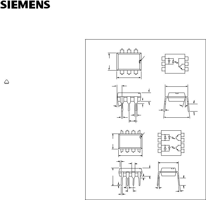
Dimensions in inches (mm)
Single Channel
3 |
2 |
1 |
|
|
|
|
|
|
pin one |
|
|
|
|
.248 (6.30) |
|
ID. |
Anode/ |
1 |
6 |
Base |
|
|
Cathode |
|
|
|
|
.256 (6.50) |
|
|
Cathode/ |
2 |
5 |
Collector |
|
|
|
Anode |
|||
|
|
|
NC |
3 |
4 |
Emitter |
4 |
5 |
6 |
|
|
|
.335 (8.50) |
|
|
|
|
.343 (8.70) |
|
|
|
|
.070 (1.78) |
.300 (7.62) |
|
|
|
.080 (2.03) |
typ. |
|
|
|
|
.130 (3.30) |
|
|
|
|
.138 (3.50) |
|
|
4° |
|
|
18° typ. |
.114 (2.90) |
typ. |
|
.031 (0.80) |
|
|
|
|
.010 (.25) typ. |
.130 (3.30) |
|
|
|
.035 (0.90) |
||
|
|
|
||
|
|
|
|
|
.018 (0.45) |
|
.031 (0.80) |
.300 (7.62) |
|
|
.035 (0.90) |
|
||
.022 (0.55) |
|
.100 (2.54) typ. |
.347 (8.82) |
|
|
|
|
|
|
Dual Channel
4 |
3 |
2 |
1 |
0.24 (6.30) |
|
|
|
0.260 |
|
|
|
5 |
6 |
7 |
8 |
|
.388 (9.86) |
|
|
|
.400 (10.16) |
|
|
Anode/ |
1 |
8 |
Emitter |
Cathode |
|
|
|
Cathode/ |
2 |
7 |
Collector |
Anode |
|||
Anode/ |
3 |
6 |
Collector |
Cathode |
|
|
|
Cathode/ |
4 |
5 |
Emitter |
Anode |
.035 (.89) |
.048 (1.22) |
.300 (7.62) |
|
.040 (1.02) |
|||
typ. |
|||
|
.052 (1.32) |
||
|
|
||
.280 (7.11) |
.130 (3.30) |
|
|
.150 (3.81) |
|
||
.330 (8.38) |
|
||
|
|
||
.014 |
|
|
|
(.35) |
|
.130 (3.30) |
|
typ. |
.020 (.51) |
||
|
.150 (3.81) |
||
|
.030 (.76) |
||
|
3° to 9° |
||
|
.033 (.84) typ. |
||
|
.008 (.20) |
||
|
.100 (2.54) typ. |
||
.016(.41) |
.012 (.31) |
||
|
|||
.020(.51) |
|
|
DESCRIPTION
The IL/ILD250/251/252 are bidirectional input optically coupled isolators consisting of two Gallium Arsenide infrared LEDs coupled to a silicon NPN phototransistor per channel.
The IL/ILD250 has a minimum CTR of 50%, the IL/ILD251 has a minimum CTR of 20%, and the IL/ILD252 has a minimum CTR
of 100%.
The IL/IL250/1/2 are single channel optocouplers. The
ILD250/1/2 has two isolated channels in a single DIP package.
These optocouplers are ideal for applications requiring AC signal detection and monitoring.
5–1
This document was created with FrameMaker 4.0.4
 Loading...