


optiPoint 500
System-Specific Telephones
Key Modules, Adapters, Accessories
Service Providers
Service Manual
P31003-E8400-A100-3-7620

*1PP31003-E8400-A100-3-7620*
1P P31003-E8400-A100-3-7620
The information in this document contains general descriptions of the technical options available, which do not always have to be present in individual cases.
The required features should therefore be specified in each individual case at the time of closing the contract.
The device conforms to the EU guideline 1999/5/EG, as attested by the CE mark.
This device has been manufactured in accordance with our certified environmental management system (ISO 14001). This process ensures that energy consumption and the use of primary raw materials are kept to a minimum, thus reducing waste production.
Siemens AG 2003 ● Information and Communication Networks, Hofmannstraße 51, D-81359 München, Germany Reference No.: P31003-E8400-A100-3-7620
Printed in the Federal Republic of Germany. ● Subject to availability. Right of modification reserved.
Contents
Figures . . . . . . . . . . . . . . . . . . . . . . . . . . . . . . . . . . . . . . . . . . . . . . . . . . . . . . . . . . . . . . . . 0-1
Tables . . . . . . . . . . . . . . . . . . . . . . . . . . . . . . . . . . . . . . . . . . . . . . . . . . . . . . . . . . . . . . . . 0-1
1 General Service Information . . . . . . . . . . . . . . . . . . . . . . . . . . . . . . . . . . . . . . . . . . . . 1-1
1.1 Service Concept . . . . . . . . . . . . . . . . . . . . . . . . . . . . . . . . . . . . . . . . . . . . . . . . . . . . . 1-1
1.2 Safety Information . . . . . . . . . . . . . . . . . . . . . . . . . . . . . . . . . . . . . . . . . . . . . . . . . . . . 1-1
1.3 Safety Symbols . . . . . . . . . . . . . . . . . . . . . . . . . . . . . . . . . . . . . . . . . . . . . . . . . . . . . . 1-2
2 Product Description . . . . . . . . . . . . . . . . . . . . . . . . . . . . . . . . . . . . . . . . . . . . . . . . . . . 2-1
2.1 optiPoint 500 Features at Hicom/HiPath . . . . . . . . . . . . . . . . . . . . . . . . . . . . . . . . . . . 2-2 2.2 Configuration Notes . . . . . . . . . . . . . . . . . . . . . . . . . . . . . . . . . . . . . . . . . . . . . . . . . . . 2-3 2.3 Telephones . . . . . . . . . . . . . . . . . . . . . . . . . . . . . . . . . . . . . . . . . . . . . . . . . . . . . . . . . 2-4
2.3.1 optiPoint 500 entry . . . . . . . . . . . . . . . . . . . . . . . . . . . . . . . . . . . . . . . . . . . . . . . . 2-4 2.3.2 optiPoint 500 economy . . . . . . . . . . . . . . . . . . . . . . . . . . . . . . . . . . . . . . . . . . . . . 2-5
2.3.3 optiPoint 500 basic . . . . . . . . . . . . . . . . . . . . . . . . . . . . . . . . . . . . . . . . . . . . . . . . 2-6
2.3.4 optiPoint 500 standard . . . . . . . . . . . . . . . . . . . . . . . . . . . . . . . . . . . . . . . . . . . . . 2-7 2.3.5 optiPoint 500 advance. . . . . . . . . . . . . . . . . . . . . . . . . . . . . . . . . . . . . . . . . . . . . . 2-8
2.4 Module Options . . . . . . . . . . . . . . . . . . . . . . . . . . . . . . . . . . . . . . . . . . . . . . . . . . . . . . 2-9
2.4.1 optiPoint 500 key module . . . . . . . . . . . . . . . . . . . . . . . . . . . . . . . . . . . . . . . . . . 2-10 2.4.2 Busy Lamp Field BLF . . . . . . . . . . . . . . . . . . . . . . . . . . . . . . . . . . . . . . . . . . . . . 2-11
2.4.2.1 Power Supply . . . . . . . . . . . . . . . . . . . . . . . . . . . . . . . . . . . . . . . . . . . . . . . . 2-11
2.4.2.2 Connection to the Terminal . . . . . . . . . . . . . . . . . . . . . . . . . . . . . . . . . . . . . 2-13 2.4.3 optiPoint 500 signature module (HiPath 4000 only) . . . . . . . . . . . . . . . . . . . . . . 2-15
2.5 Accessories . . . . . . . . . . . . . . . . . . . . . . . . . . . . . . . . . . . . . . . . . . . . . . . . . . . . . . . . 2-16
2.5.1 External Speaker/Desk Microphone . . . . . . . . . . . . . . . . . . . . . . . . . . . . . . . . . . 2-16 2.5.2 optiPoint Headsets . . . . . . . . . . . . . . . . . . . . . . . . . . . . . . . . . . . . . . . . . . . . . . . 2-17
2.5.3 Local Power Supply Unit . . . . . . . . . . . . . . . . . . . . . . . . . . . . . . . . . . . . . . . . . . . 2-18
2.5.4 Accessory Pack. . . . . . . . . . . . . . . . . . . . . . . . . . . . . . . . . . . . . . . . . . . . . . . . . . 2-19 2.5.5 Online Key Labeling Tool . . . . . . . . . . . . . . . . . . . . . . . . . . . . . . . . . . . . . . . . . . 2-19
2.5.6 Wall Mounting . . . . . . . . . . . . . . . . . . . . . . . . . . . . . . . . . . . . . . . . . . . . . . . . . . . 2-19
2.6 Technical Data . . . . . . . . . . . . . . . . . . . . . . . . . . . . . . . . . . . . . . . . . . . . . . . . . . . . . . 2-20 2.6.1 Asset ID. . . . . . . . . . . . . . . . . . . . . . . . . . . . . . . . . . . . . . . . . . . . . . . . . . . . . . . . 2-20 2.6.2 Environmental Conditions . . . . . . . . . . . . . . . . . . . . . . . . . . . . . . . . . . . . . . . . . . 2-20 2.6.3 Ranges . . . . . . . . . . . . . . . . . . . . . . . . . . . . . . . . . . . . . . . . . . . . . . . . . . . . . . . . 2-21 2.6.4 UP0/E Interface. . . . . . . . . . . . . . . . . . . . . . . . . . . . . . . . . . . . . . . . . . . . . . . . . . 2-21 2.6.5 USB 1.1 Interface . . . . . . . . . . . . . . . . . . . . . . . . . . . . . . . . . . . . . . . . . . . . . . . . 2-21
3 Startup . . . . . . . . . . . . . . . . . . . . . . . . . . . . . . . . . . . . . . . . . . . . . . . . . . . . . . . . . . . . . . 3-1
3.1 Unpacking the Box. . . . . . . . . . . . . . . . . . . . . . . . . . . . . . . . . . . . . . . . . . . . . . . . . . . . 3-1
3.2 Setting Up the Telephone . . . . . . . . . . . . . . . . . . . . . . . . . . . . . . . . . . . . . . . . . . . . . . 3-1
3.3 Keypad and Control Panel . . . . . . . . . . . . . . . . . . . . . . . . . . . . . . . . . . . . . . . . . . . . . . 3-1
P31003-E8400-A100-3-7620 |
0-1 |
Service Manual |
3.4 Date and Time Indicator . . . . . . . . . . . . . . . . . . . . . . . . . . . . . . . . . . . . . . . . . . . . . . . . 3-2 3.5 Ports on the Underside of the Telephone . . . . . . . . . . . . . . . . . . . . . . . . . . . . . . . . . . . 3-3 3.6 Telephone Tests . . . . . . . . . . . . . . . . . . . . . . . . . . . . . . . . . . . . . . . . . . . . . . . . . . . . . . 3-4 3.7 Block Diagrams. . . . . . . . . . . . . . . . . . . . . . . . . . . . . . . . . . . . . . . . . . . . . . . . . . . . . . . 3-7
4 Private Network Termination Units . . . . . . . . . . . . . . . . . . . . . . . . . . . . . . . . . . . . . . . 4-1
4.1 PNT Private Network Termination. . . . . . . . . . . . . . . . . . . . . . . . . . . . . . . . . . . . . . . . . 4-2 4.2 PNT E Private Network Termination . . . . . . . . . . . . . . . . . . . . . . . . . . . . . . . . . . . . . . . 4-2 4.3 PNT Q Private Network Termination. . . . . . . . . . . . . . . . . . . . . . . . . . . . . . . . . . . . . . . 4-2 4.4 Distance Adapter (UCON S and M) at Hicom 300/300 E and HiPath 4000 . . . . . . . . . 4-2
5 Option Adapters and Ports . . . . . . . . . . . . . . . . . . . . . . . . . . . . . . . . . . . . . . . . . . . . . . 5-1
5.1 Adapter Slots. . . . . . . . . . . . . . . . . . . . . . . . . . . . . . . . . . . . . . . . . . . . . . . . . . . . . . . . . 5-3 5.2 optiPoint 500 acoustic adapter . . . . . . . . . . . . . . . . . . . . . . . . . . . . . . . . . . . . . . . . . . . 5-4 5.2.1 Electrical Requirements of the Headset . . . . . . . . . . . . . . . . . . . . . . . . . . . . . . . . . 5-6 5.2.2 Floating Contacts . . . . . . . . . . . . . . . . . . . . . . . . . . . . . . . . . . . . . . . . . . . . . . . . . . 5-7
5.3 optiPoint 500 Analog Adapters . . . . . . . . . . . . . . . . . . . . . . . . . . . . . . . . . . . . . . . . . . . 5-8
5.4 optiPoint 500 ISDN Adapter . . . . . . . . . . . . . . . . . . . . . . . . . . . . . . . . . . . . . . . . . . . . 5-10
5.5 optiPoint 500 Phone Adapter (Host/Client) . . . . . . . . . . . . . . . . . . . . . . . . . . . . . . . . . 5-11 5.6 optiPoint 500 recorder adapter . . . . . . . . . . . . . . . . . . . . . . . . . . . . . . . . . . . . . . . . . . 5-12
5.7 Port Overview . . . . . . . . . . . . . . . . . . . . . . . . . . . . . . . . . . . . . . . . . . . . . . . . . . . . . . . 5-15
6 CallBridge . . . . . . . . . . . . . . . . . . . . . . . . . . . . . . . . . . . . . . . . . . . . . . . . . . . . . . . . . . . . 6-1
6.1 CallBridge TU . . . . . . . . . . . . . . . . . . . . . . . . . . . . . . . . . . . . . . . . . . . . . . . . . . . . . . . . 6-1
6.2 CallBridge for Data . . . . . . . . . . . . . . . . . . . . . . . . . . . . . . . . . . . . . . . . . . . . . . . . . . . . 6-2
7 IP Adapter . . . . . . . . . . . . . . . . . . . . . . . . . . . . . . . . . . . . . . . . . . . . . . . . . . . . . . . . . . . . 7-1
7.1 optiPoint IPadapter Installation . . . . . . . . . . . . . . . . . . . . . . . . . . . . . . . . . . . . . . . . . . . 7-2
7.2 Connection to the Terminal . . . . . . . . . . . . . . . . . . . . . . . . . . . . . . . . . . . . . . . . . . . . . . 7-3
7.3 Connection to the System . . . . . . . . . . . . . . . . . . . . . . . . . . . . . . . . . . . . . . . . . . . . . . . 7-4 7.4 Administration Via the Web Browser. . . . . . . . . . . . . . . . . . . . . . . . . . . . . . . . . . . . . . . 7-5
7.5 Administration via optiPoint 500 . . . . . . . . . . . . . . . . . . . . . . . . . . . . . . . . . . . . . . . . . 7-22
7.6 Configuration Examples . . . . . . . . . . . . . . . . . . . . . . . . . . . . . . . . . . . . . . . . . . . . . . . 7-31
8 Troubleshooting. . . . . . . . . . . . . . . . . . . . . . . . . . . . . . . . . . . . . . . . . . . . . . . . . . . . . . . 8-1
8.1 Test Loops 3 and 4 . . . . . . . . . . . . . . . . . . . . . . . . . . . . . . . . . . . . . . . . . . . . . . . . . . . . 8-1
8.2 Reboot. . . . . . . . . . . . . . . . . . . . . . . . . . . . . . . . . . . . . . . . . . . . . . . . . . . . . . . . . . . . . . 8-1
9 Ordering Information . . . . . . . . . . . . . . . . . . . . . . . . . . . . . . . . . . . . . . . . . . . . . . . . . . . 9-1
9.1 Products and Spare Parts . . . . . . . . . . . . . . . . . . . . . . . . . . . . . . . . . . . . . . . . . . . . . . . 9-1
9.1.1 Initial Equipment: Telephone Models, Optiset E Key Modules, and Adapters . . . . 9-1
9.1.2 Accessories, Spare Parts, Miscellaneous . . . . . . . . . . . . . . . . . . . . . . . . . . . . . . . 9-3
9.2 Documentation . . . . . . . . . . . . . . . . . . . . . . . . . . . . . . . . . . . . . . . . . . . . . . . . . . . . . . . 9-6
9.3 Order Addresses . . . . . . . . . . . . . . . . . . . . . . . . . . . . . . . . . . . . . . . . . . . . . . . . . . . . . . 9-7
9.4 After-Sales Service and Repair. . . . . . . . . . . . . . . . . . . . . . . . . . . . . . . . . . . . . . . . . . . 9-8
9.5 Intranet Addresses . . . . . . . . . . . . . . . . . . . . . . . . . . . . . . . . . . . . . . . . . . . . . . . . . . . . 9-9
Abbreviations . . . . . . . . . . . . . . . . . . . . . . . . . . . . . . . . . . . . . . . . . . . . . . . . . . . . . . . . . . Y-1
|
P31003-E8400-A100-3-7620 |
0-2 |
Service Manual |
Index . . . . . . . . . . . . . . . . . . . . . . . . . . . . . . . . . . . . . . . . . . . . . . . . . . . . . . . . . . . . . . . . . Z-1
P31003-E8400-A100-3-7620 |
0-3 |
Service Manual |
|
P31003-E8400-A100-3-7620 |
0-4 |
Service Manual |
Figures
Figure 2-1 optiPoint 500 entry. . . . . . . . . . . . . . . . . . . . . . . . . . . . . . . . . . . . . . . . . . . . . . . 2-4
Figure 2-2 optiPoint 500 economy . . . . . . . . . . . . . . . . . . . . . . . . . . . . . . . . . . . . . . . . . . . 2-5 Figure 2-3 optiPoint 500 basic . . . . . . . . . . . . . . . . . . . . . . . . . . . . . . . . . . . . . . . . . . . . . . 2-6 Figure 2-4 optiPoint 500 standard . . . . . . . . . . . . . . . . . . . . . . . . . . . . . . . . . . . . . . . . . . . . 2-7 Figure 2-5 optiPoint 500 advance . . . . . . . . . . . . . . . . . . . . . . . . . . . . . . . . . . . . . . . . . . . . 2-8 Figure 2-6 Power supply to BLF . . . . . . . . . . . . . . . . . . . . . . . . . . . . . . . . . . . . . . . . . . . . 2-12 Figure 3-1 Keypad and control panel (optiPoint 500 standard). . . . . . . . . . . . . . . . . . . . . . 3-1 Figure 3-2 Jacks on the underside of the telephone (optiPoint 500 advance) . . . . . . . . . . 3-3 Figure 3-3 optiPoint 500 entry, economy block diagram . . . . . . . . . . . . . . . . . . . . . . . . . . . 3-7 Figure 3-4 optiPoint 500 basic, standard and advance block diagram . . . . . . . . . . . . . . . . 3-8 Figure 4-1 Private network termination units. . . . . . . . . . . . . . . . . . . . . . . . . . . . . . . . . . . . 4-1
Figure 5-1 Jacks on the underside of the telephone (optiPoint 500 advance) . . . . . . . . . . 5-3 Figure 5-2 Recorder adapter. . . . . . . . . . . . . . . . . . . . . . . . . . . . . . . . . . . . . . . . . . . . . . . 5-12
Figure 5-3 Connection example: host, SPA, Client, 2 SNG - Power supply unit dependent on the configuration5-14
Figure 7-1 System connection of optiPoint IPadapter . . . . . . . . . . . . . . . . . . . . . . . . . . . . . 7-2
Figure 7-2 Overview: connecting an optiPoint IPadapter to the terminal . . . . . . . . . . . . . . 7-3
Figure 7-3 Overview: connecting an optiPoint IPadapter to the system . . . . . . . . . . . . . . . 7-4 Figure 7-4 Electrical connection of the optiPoint IPadapter . . . . . . . . . . . . . . . . . . . . . . . . 7-4
Figure 7-5 Faults shown on optiPoint display . . . . . . . . . . . . . . . . . . . . . . . . . . . . . . . . . . 7-23
Figure 7-6 Error codes for configuration settings . . . . . . . . . . . . . . . . . . . . . . . . . . . . . . . 7-24 Figure 7-7 WEB access to the IPadapter . . . . . . . . . . . . . . . . . . . . . . . . . . . . . . . . . . . . . 7-32
Figure 7-8 WEB page administration . . . . . . . . . . . . . . . . . . . . . . . . . . . . . . . . . . . . . . . . 7-33
Figure 7-9 IP address and routing. . . . . . . . . . . . . . . . . . . . . . . . . . . . . . . . . . . . . . . . . . . 7-34 Figure 7-10Settings in Assistant Office. . . . . . . . . . . . . . . . . . . . . . . . . . . . . . . . . . . . . . . 7-35
Figure 7-11optiPoint IPadapter homepage. . . . . . . . . . . . . . . . . . . . . . . . . . . . . . . . . . . . 7-36
Figure 7-12WEB page administration . . . . . . . . . . . . . . . . . . . . . . . . . . . . . . . . . . . . . . . . 7-37 Figure 7-13IP address and routing . . . . . . . . . . . . . . . . . . . . . . . . . . . . . . . . . . . . . . . . . . 7-38
P31003-E8400-A100-3-7620 |
0-1 |
Service Manual |
|
P31003-E8400-A100-3-7620 |
0-2 |
Service Manual |
Tables
Table 2-1 |
Features of optiPoint 500 entry . . . . . . . . . . . . . . . . . . . . . . . . . . . . . . |
. 2-4 |
Table 2-2 |
Features of optiPoint 500 economy . . . . . . . . . . . . . . . . . . . . . . . . . . . |
. 2-5 |
Table 2-3 |
Features of optiPoint 500 basic . . . . . . . . . . . . . . . . . . . . . . . . . . . . . . |
. 2-6 |
Table 2-4 |
Features of optiPoint 500 standard . . . . . . . . . . . . . . . . . . . . . . . . . . . |
. 2-7 |
Table 2-5 |
Features of optiPoint 500 advance . . . . . . . . . . . . . . . . . . . . . . . . . . . . |
. 2-8 |
Table 2-6 |
Headsets . . . . . . . . . . . . . . . . . . . . . . . . . . . . . . . . . . . . . . . . . . . . . . . |
2-17 |
Table 2-7 |
Environmental conditions . . . . . . . . . . . . . . . . . . . . . . . . . . . . . . . . . . . |
2-20 |
Table 2-8 |
UP0/E interfaces: technical data . . . . . . . . . . . . . . . . . . . . . . . . . . . . . |
2-21 |
Table 3-1 |
Telephone test for HiPath 4000/Hicom 300 H . . . . . . . . . . . . . . . . . . . |
. 3-4 |
Table 7-1 |
Pin assignment . . . . . . . . . . . . . . . . . . . . . . . . . . . . . . . . . . . . . . . . . . . |
. 7-4 |
Table 7-2 |
FTP parameters . . . . . . . . . . . . . . . . . . . . . . . . . . . . . . . . . . . . . . . . . . |
7-14 |
Table 7-3 |
Error messages . . . . . . . . . . . . . . . . . . . . . . . . . . . . . . . . . . . . . . . . . . |
7-15 |
Table 9-1 |
opiPoint 500 models . . . . . . . . . . . . . . . . . . . . . . . . . . . . . . . . . . . . . . . |
. 9-1 |
Table 9-2 |
optiPoint 500 adapters . . . . . . . . . . . . . . . . . . . . . . . . . . . . . . . . . . . . . |
. 9-1 |
Table 9-3 |
optiPoint 500 without HS . . . . . . . . . . . . . . . . . . . . . . . . . . . . . . . . . . . |
. 9-2 |
Table 9-4 |
optiPoint 500 handset with/without logo . . . . . . . . . . . . . . . . . . . . . . . . |
. 9-3 |
Table 9-5 |
optiPoint 500 more spare parts . . . . . . . . . . . . . . . . . . . . . . . . . . . . . . |
. 9-3 |
Table 9-7 |
Order addresses . . . . . . . . . . . . . . . . . . . . . . . . . . . . . . . . . . . . . . . . . . |
. 9-7 |
Table 9-8 |
Intranet addresses . . . . . . . . . . . . . . . . . . . . . . . . . . . . . . . . . . . . . . . . |
. 9-9 |
P31003-E8400-A100-3-7620 |
0-1 |
Service Manual |
|
P31003-E8400-A100-3-7620 |
0-2 |
Service Manual |
General Service Information
Service Concept
1 General Service Information
1.1Service Concept
Faulty terminals and adaptors can be debugged on site by exchanging components/adaptors or replacing individual faulty elements, such as handsets, cords, covering panels, etc.
1.2Safety Information
Setting Up the Equipment
The equipment is set up by the user or service technician. Training or orientation on how to use optiPoint500 device parts is not neccessary.
A mains socket may be necessary for operating telephones and options, depending on the scope of the configuration.
If more telephones are to be added later on, make sure that an adequate number of mains sockets are available for connecting the required local power supply units.
Damage to the Equipment
Only use tools and testers suitable for the job. Do not put devices with external damage into service.
Laying Cables
Lay the power and connection cables in such a way as to avoid accidents (no tripping) and damage to the cables.
Troubleshooting and Replacing Boards
Note the following when replacing boards:
●Service tasks should only be carried out by authorized personnel.
●Always replace boards with original spare parts.
●Always disconnect the system from the power source before replacing boards.
●Always following the instructions and take the proper precautions when handling boards that contain electrostatically sensitive devices.
Protecting Electrostatically Sensitive Devices
To protect electrostatically sensitive devices (ESD):
●Always put on an earthed wristband before performing any work on PC boards.
P31003-E8400-A100-3-7620 |
1-1 |
Service Manual |

General Service Information
Safety Symbols
●Transport PC boards only in suitable protective packaging.
●When working on PC boards, always ensure that they are placed on a grounded conducting base.
●Always use soldering iron for soldering.
1.3Safety Symbols
The following symbols are used in this manual to identify possible sources of danger.
Data Protection and Data Security
>Helpful suggestions
Hazards that can cause damage to the hardware and software and even 7 destroy it.
3 General heat dissipation
4 Electrostatically sensitive devices
Using Personal Data
In Germany, the processing and use of personal data are subject to various regulations, including the regulations of the Federal Data Protection Law (Bundesdatenschutzgesetz = BDSG).
For other countries, please follow the appropriate national laws.
The aim of data protection is to protect the rights of individuals being affected by use of their personal data.
Guidelines for Members of Siemens Staff
Siemens staff are required to observe business and data secrecy as a result of the company’s work rules.
In order to ensure that the statutory requirements during service - whether during "on-site service" or during "remote service" - are consistently met, you should always observe the following rules. You will not only maintain the interests of your and our customers, you will also avoid personal consequences.
1-2 |
P31003-E8400-A100-3-7620 |
Service Manual |
General Service Information
Safety Symbols
Guidelines for Using Data
Conscious action helps maintain data protection and data security:
●Ensure that only appropriately authorized persons have access to customer data.
●Take full advantage of password assignment options; do not allow unauthorized persons to gain access to passwords by writing them down on a piece of paper or through other means.
●Ensure that no unauthorized person is able to process (store, modify, transmit, disable, delete) or use customer data in any way.
●Prevent unauthorized persons from gaining access to data media, e.g. on backup disks or printed reports. This applies to service calls as well as to storage and transport.
●Ensure that data media which are no longer required are completely destroyed. Ensure that no papers remain generally available.
●Work together with your contacts at the customer’s company: This creates mutual confidence and reduces your own workload.
P31003-E8400-A100-3-7620 |
1-3 |
Service Manual |
General Service Information
Safety Symbols
1-4 |
P31003-E8400-A100-3-7620 |
Service Manual |
Product Description
2 Product Description
OptiPoint 500 telephones are designed to facilitate access to the features of HiPath 3000/Hicom 150H and HiPath 4000/Hicom 300/300H. See the chapter on “Startup” for configuration information.
The operating principle is characterized by three dialog keys, which in conjunction with the display, facilitate interactive user prompting. In addition, the key LED principle indicates activated functions.
The numerous control functions are clearly laid out in submenus and can be read on the display (excluding "entry" model). Features can also be selected directly via the service key using a code. Important functions can be programmed on individual function keys.
optiPoint 500 telephones |
|
economy |
|
standard |
advance |
|
entry |
basic |
|||
|
|
|
|
|
|
Function keys with LEDs |
8 |
12 |
12 |
12 |
19 |
|
|
|
|
|
|
12-key keypad |
• |
• |
• |
• |
• |
|
|
|
|
|
|
2 keys (plus/minus) |
• |
• |
• |
• |
• |
|
|
|
|
|
|
Open listening |
• |
• |
• |
|
|
|
|
|
|
|
|
Full duplex speakerphone mode |
|
|
|
• |
• |
|
|
|
|
|
|
Adapter slots |
|
|
1 |
1 |
2 |
|
|
|
|
|
|
USB 1.1 Interface |
|
|
• |
• |
• |
|
|
|
|
|
|
Headset port (121 TR9-5) |
|
|
|
|
• |
|
|
|
|
|
|
3 dialog keys |
|
• |
• |
• |
• |
|
|
|
|
|
|
Display (characters) |
|
2 x 24 |
2 x 24 |
2 x 24 |
2 x 24 |
|
|
|
|
|
|
Display background lighting |
|
|
|
|
• |
|
|
|
|
|
|
Interface for max. 2 key modules |
|
|
|
|
|
2 key modules or |
|
|
• |
• |
• |
1 key module and 1 signature module |
|
|
• |
• |
• |
|
|
|
|
|
|
Wall mounting |
• |
• |
• |
• |
• |
|
|
|
|
|
|
P31003-E8400-A100-3-7620 |
2-1 |
Service Manual |
Product Description
optiPoint 500 Features at Hicom/HiPath
2.1optiPoint 500 Features at Hicom/HiPath
Features when Connecting to Hicom and HiPath
Optiset E IDs for telephones and options must be used when connecting optiPoint500 to one of the following systems:
●HiPath AllServe 150
●HiPath 3000
●Hicom 150 E/150 H
●Hicom 150 E/H Office
●Hicom 300 E/300 H Features
●optiset E/optiPoint 500 mixed mode possible at SLMO.
●optiset E/optiPoint 500 mixed mode possible for host/client configuration with phone adapters.
●PC connection via integrated USB 1.1 interface (excluding entry) and special USB (client) cables with right-angle plug.
●CTI applications based on CallBridge TU for TAPI 2.1 available free of charge on the intranet (prerequisite: Windows 98 SE or Windows 2000).
●In optiPoint 500 advance, only 12 of the 19 Hicom/HiPath function keys are configurable.
The remaining function keys can however be assigned destination call numbers via the optiPoint menu.
Additional Features when Connecting optiPoint 500 to HiPath 4000
●
●
●
●
●
●
Support for the new optiPoint 500 IDs
Additional ring tones (16 instead of 8)
Call acceptance/cleardown function for “cordless” headsets Mobile station” for optiPoint signature module
Busy lamp/door-opener control via a programmable key Adjustable display contrast (4 levels)
2-2 |
P31003-E8400-A100-3-7620 |
Service Manual |

Product Description
Configuration Notes
Modules (Add-On Components) and Adapters
●Modules (see Section 2.4 on page 2-9)
The optiPoint 500 operating panel (basic model and later versions) can be expanded
–using key modules with function keys
–a signature module or
–a busy lamp field
●Adapters (see Section 5)
By using adapters in conjunction with telephones, specific workstation requirements can be satisfied.
Additional devices can be directly connected to the workstation (e.g. PC, fax machines, telephones, headsets) by simply adding different adapters to the underside of the telephone.
2.2Configuration Notes
●Mixed optiset E/optiPoint 500 telephone configurations possible on UP0/E
●Mixed optiset E/optiPoint 500 host/client configuration (phone adapter) possible
●The options (key modules, adapters) for optiset E (5-volt technology) and optiPoint 500 telephones (3.3-volt technology) are not interchangeable
●PC connection to optiPoint 500 via USB1.1 interface (except for the “entry” and “economy” models)
–only possible with Windows 98 SE or Windows 2000 with USB support
–optiPoint 500 USB client interface, conforming to USB Specification 1.1
–USB cable with right-angle plug available for optiPoint 500 basic/standard/advance
–integrated USB1.1 interface replaces optiset E control/data adapter for CTI functions
–integrated USB1.1 interface replaces optiset E with ISDN adapter for modem, NDISWAN miniport, and CAPI applications
●CallBridge TU (PC software available free of charge) offers CTI platform for TAPI 2.1- based CTI applications; CallBridge TA is also still available for optiset E adapter
CallBridge for Data offers NDISWAN miniport, CAPI 2.0, and ComPort/modem interface for data applications
No firewall has been implemented - there could be a security risk if both a LAN port 7 and CallBridge for Data are installed.
P31003-E8400-A100-3-7620 |
2-3 |
Service Manual |
Product Description
Telephones
2.3Telephones
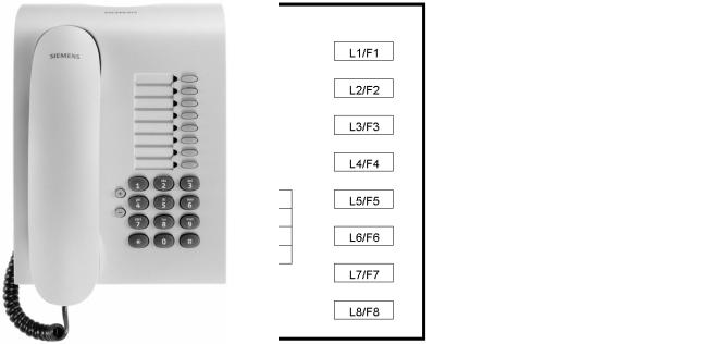
2.3.1optiPoint 500 entry
For stations at which a display is not required (e.g. lifts, entrance halls, etc.)
Figure 2-1 |
optiPoint 500 entry |
|
|
|
|
|
|
|
|
Controls |
Connectivity |
|
|
||
● 8 function keys with LEDs |
no adapter slots |
||
● 2 adjustable keys (plus/minus) for |
|
||
– |
ringer volume |
|
|
– |
ringer pitch |
|
|
– |
alerting tone |
|
|
– open listening (not speakerphone mode) |
|
||
● Suitable for wall mounting |
|
||
|
|
|
|
Table 2-1 |
Features of optiPoint 500 entry |
|
|
2-4 |
P31003-E8400-A100-3-7620 |
Service Manual |
Product Description
Telephones
2.3.2optiPoint 500 economy
|
Figure 2-2 |
optiPoint 500 economy |
|
|
|
|
|
|
|
|
|
|
|
|
Controls |
Connectivity |
|
|
|
|
|
||
|
● 12 function keys with LEDs |
None |
|
||
|
● Open listening |
|
|
||
|
● Alphanumeric LCD display with |
|
|
||
|
two lines and 24 characters per line, tiltable. |
|
|
||
|
● 3 dialog keys for interactive user prompting: “Yes”, |
|
|
||
|
“Back” and “Next” |
|
|
||
|
● 2 adjustable keys (plus/minus) for |
|
|
||
|
– |
ringer volume, |
|
|
|
|
– |
ringer pitch, |
|
|
|
|
– |
alerting tone, |
|
|
|
|
– |
display contrast |
|
|
|
|
● Suitable for wall mounting |
|
|
||
|
|
|
|
|
|
|
Table 2-2 |
Features of optiPoint 500 economy |
|
|
|
P31003-E8400-A100-3-7620 |
2-5 |
||||
Service Manual |
|
||||

Product Description
Telephones
2.3.3optiPoint 500 basic
Figure 2-3 |
optiPoint 500 basic |
|
|
|
|
|
|
|
|
|
|
|
|
Controls |
|
Connectivity |
|
|
|
|
|
||
● 12 function keys with LEDs |
● |
USB 1.1 interface |
|
||
● Open listening |
● |
1 adapter slot |
|
||
● Tiltable alphanumeric LCD display with |
● 1 interface for max. 2 key modules |
|
|||
2 lines and 24 characters per line. |
|
– optiPoint 500 Key Module |
|
||
|
|
|
|
|
|
● 3 dialog keys for interactive user prompts: |
|
– optiPoint 500 Signature Module |
|
||
"Yes", "Back" and "Continue" |
|
|
|||
|
|
|
|||
● 2 adjustable keys (plus/minus) for |
|
|
|
||
– |
ringer volume |
|
|
|
|
– |
ringer pitch |
|
|
|
|
– |
alerting tone |
|
|
|
|
– |
display contrast |
|
|
|
|
● Suitable for wall mounting |
|
|
|
||
|
|
|
|
|
|
Table 2-3 |
Features of optiPoint 500 basic |
|
|
|
|
2-6 |
|
|
|
P31003-E8400-A100-3-7620 |
|
|
|
|
Service Manual |
||
Product Description
Telephones
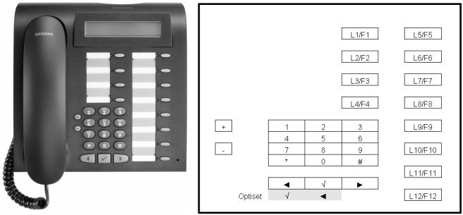
2.3.4optiPoint 500 standard
|
Figure 2-4 |
optiPoint 500 standard |
|
|
|
|
|
|
|
|
|
|
|
|
Controls |
|
Special Features |
|
|
|
|
||
|
● 12 function keys with LEDs |
● |
USB 1.1 interface |
||
|
● Full duplex speakerphone mode with |
● |
1 adapter slot |
||
|
echo suppression for room adaptation |
● |
1 interface for max. 2 key modules |
||
|
|
|
|
||
|
● Tiltable alphanumeric LCD display with |
|
– optiPoint 500 key module |
||
|
2 lines and 24 characters per line. |
|
|||
|
|
|
|||
|
● 3 dialog keys for interactive user prompts: |
|
– optiPoint 500 signature module |
||
|
|
|
|||
|
Yes, Back, and Continue |
|
|
||
|
● 2 adjustable keys (plus/minus) for |
|
|
||
|
– |
ringer volume |
|
|
|
|
– |
ringer pitch |
|
|
|
|
– |
handsfree quality |
|
|
|
|
– |
alerting tone |
|
|
|
|
– |
display contrast |
|
|
|
|
● Suitable for wall mounting |
|
|
||
|
|
|
|
|
|
|
Table 2-4 |
Features of optiPoint 500 standard |
|
||
P31003-E8400-A100-3-7620 |
|
2-7 |
|||
Service Manual |
|
|
|||
Product Description
Telephones
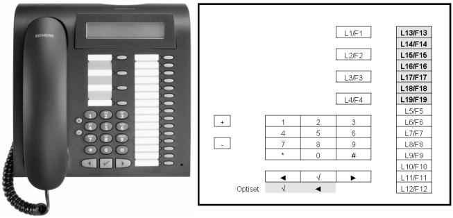
2.3.5optiPoint 500 advance
Figure 2-5 |
optiPoint 500 advance |
|
|
|
|
|
|
|
|
|
|
|
Controls |
|
|
Special Features |
|
|
|
|
|||
19 function keys with LEDs |
● |
USB 1.1 interface |
|||
Full duplex speakerphone mode with echo sup- |
● |
2 adapter slots |
|||
pression for room adaptation |
|||||
|
|
|
|||
Tiltable alphanumeric LCD display with 2 lines |
● 1 headset port (121 TR9-5) |
||||
|
|
|
|||
and 24 characters per line. |
● |
1 interface for max. 2 key modules |
|||
additional with background lighting, |
|
– |
optiPoint key module |
||
remains lit for approx. 5 s. |
|
||||
|
|
|
|||
3 dialog keys for interactive user prompts: Yes, |
|
– |
optiPoint signature module |
||
|
|
|
|||
Back, and Continue |
|
|
|
||
2 adjustable keys (plus/minus) for ringer vol- |
|
|
|
||
ume, ringer pitch, handsfree quality, alerting |
|
|
|
||
tone and display contrast |
|
|
|
||
Suitable for wall mounting |
|
|
|
||
|
|
|
|
|
|
Table 2-5 |
Features of optiPoint 500 advance |
|
|
||
If optiPoint 500 advance is connected to Hicom or HiPath 3000 or AllServe 150, only 12 function keys can be configured via Hicom/HiPath.
The remaining function keys can be configured as call destination keys via the optiPoint500 advance menu.
2-8 |
P31003-E8400-A100-3-7620 |
Service Manual |
Product Description
Module Options
2.4Module Options
Adapters facilitate flexible expansion of the telephone workstation at optiPoint 500 basic, standard and advance system telephones, by means of individual add-on components.
Configuration Notes
●Connection of max. 2 modules (key modules) to the basic, standard and advance models.
●A local power supply unit may be necessary, depending on the range and number of key modules (max 2).
Use the optiPoint 500 "Telephone Test"/"Feeding Range" service menu items to check if the power supply is sufficient.
●optiPoint 500 entry cannot be configured as the primary telephone in a primary/client configuration
(see Section 5.5 on page 5-11).
●Whenever making changes to the configuration, disconnect the primary telephone from Hicom/HiPath. Doing so triggers a reset when the device is connected again, providing the system with the new configuration in the setup message.
●Only one headset/acoustic adapter is permitted per telephone.
P31003-E8400-A100-3-7620 |
2-9 |
Service Manual |
Product Description
Module Options
2.4.1optiPoint 500 key module
The key module on the basic, standard and advance models is used for saving call numbers and functions (e.g. callback, conference, last number redial, etc.)
It features:
●16 function keys
●16 LEDs for visual signaling of the activated functions and keys.
Shift key
One of the keys is assigned the shift function. 30 name destination keys can be programmed using the shift key.
Physical mounting
Max. 2 key modules can be connected to optiPoint 500.
16 function keys
16 LEDs
2-10 |
P31003-E8400-A100-3-7620 |
Service Manual |
Product Description
Module Options
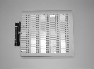
2.4.2Busy Lamp Field BLF
The BLF is a key module for optiPoint 500 and 600 that can be connected to the telephone over an 8-pin RJ45 communications port.
It can be used in the HiPath 3000/Hicom 150E/H and HiPath AllServe 150 systems and has the same functions as the existing BLF on optiset E telephones.
The BLF on the basic, standard and advance models allows phone numbers and functions to be saved (e.g. callback, conference, last number redial, etc.)
It has
●
●
90 function keys,
90 LEDs for visual signaling of the activated functions and keys.
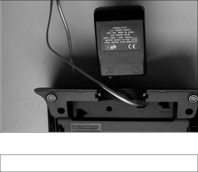
2.4.2.1Power Supply
The BLF has its own local power supply. If you want to connect two BLFs, you need only one local power supply for them both (i.e. the power supply of the first BLF can be used for the second BLF as well).
The BLF uses the same power supply (power supply unit 2x35V) and connector as the optiPoint
500 a/b adapter (also see chapter “Accessories“ --> “Mains adapter“).
The output of power supply must be connected directly with the optiPoint BLF.
P31003-E8400-A100-3-7620 |
2-11 |
Service Manual |
Product Description
Module Options
Figure 2-6 Power supply to BLF
When connecting the BLF the configuration should be checked to ensure that it cor- >responds with the telephones/auxiliary modules which are connected..
2-12 |
P31003-E8400-A100-3-7620 |
Service Manual |

Product Description
Module Options
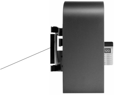
2.4.2.2Connection to the Terminal
The following connection configurations A - D are possible:
A
optiPoint 500 |
optiPoint BLF |
Phone |
|
B
optiPoint 500 |
optiPoint BLF |
optiPoint BLF |
Phone |
|
|
C
optiPoint 500 |
optiPoint |
optiPoint BLF |
Phone |
Key Module |
|
D
optiPoint 500 |
optiPoint |
optiPoint BLF |
optiPoint BLF |
Phone |
Key Module |
|
|
You can also connect the BLF to the terminal first in combination C and D in connection with a key module.
With releases lower than 3.0, it is not possible to use an optiPoint 500 advance with
>the connection configurations C and D.
P31003-E8400-A100-3-7620 |
2-13 |
Service Manual |
Product Description
Module Options
Interface Description: MW8/8 (RJ45)
Pin 1 |
Pin 2 |
Pin 3 |
Pin 4 |
Pin 5 |
Pin 6 |
Pin 7 |
Pin 8 |
|
|
|
|
|
|
|
|
side car |
SPI master |
nc |
+ 3,3V |
nc |
DGND |
SPI clock |
SPI master in/ |
CS |
out/slave in |
|
|
|
|
|
slave out |
|
|
|
|
|
|
|
|
2-14 |
P31003-E8400-A100-3-7620 |
Service Manual |
Product Description
Module Options
2.4.3optiPoint 500 signature module (HiPath 4000 only)
The optiPoint 500 signature module is a chip card reader add-on device for the basic, standard and advance models.
The key module is a simple option for upgrading an existing telephone to chip card technology.
Physical mounting
I2C Bus Memory Cards
Customized, programmable I2C cards are required for using signature modules. These can be obtained from Siemens AG: Rainer.eickholt@fthw.siemens.de (see Section 9.3)
P31003-E8400-A100-3-7620 |
2-15 |
Service Manual |
Product Description
Accessories
2.5Accessories
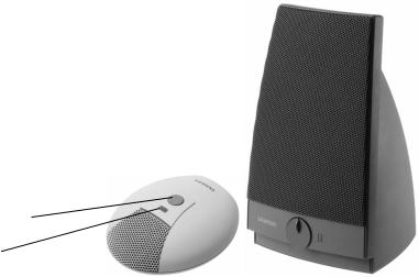
2.5.1External Speaker/Desk Microphone
These parts feature magnetic shielding to protect magnetic data media and monitors as well as a device to protect against incoming radiation for electromagnetic compatibility (especially in conjunction with mobile phones).
To avoid feedback, position the desk microphone and the external speaker as far away from each other as possible.
Mute key
LED for on/off display
Desk Microphone
The desk microphone replaces the microphone that is integrated in the telephone and assists in optimizing the "speakerphone" function in poor acoustic conditions.
If the external speaker button on the telephone is pressed, an LED lights up on the microphone to show that the microphone is now ready to record.
The microphone can be switched off by pressing the mute key. Deactivation is confirmed when the LED goes out.
optiset E External Speaker
The active external speaker enhances the speaker already integrated in the telephone and improves the acoustic features and is therefore most suitable for telephone conferences.
When the external speaker is connected to the power network, an LED lights up to show that is operational. The external speaker button on the telephone activates this function.
The base volume can be adjusted in line with the given room conditions using the automatic volume control key on the front of the telephone. Volume control during a call is controlled via the volume key on the telephone.
2-16 |
P31003-E8400-A100-3-7620 |
Service Manual |
 Loading...