


Hicom 100 E
Hicom 108
Hicom 112
Hicom 118
Hicom 118-2
Service manual
A31003-K16-X001-3-7620

Issued by
Information and Communication Networks Hofmannstrasse 51, D-81359 München
ã Siemens AG 1999. All rights reserved. Subject to availability.
Right of modification reserved.
Siemens Aktiengesellschaft
Reference No.: A31003-K16-X001-3-7620
Printed in the Federal Republic of Germany.

Hicom 100 E
Hicom 108
Hicom 112
Service manual
A31003-K16-X001-3-7620
Important Information
1
System data
2
Overview of modules
3
Features
4
Installation
5
Initial operation
6
Administration and maintenance
7
Least Cost Routing (LCR)
8
Maintenance and repair
9
Programming guide
10
Plus products
11
Euroset line 36/Hicom 118-2
12
--
13
--
14
--
15
Table of Contents
Table of Contents
1 Important Information. . . . . . . . . . . . . . . . . . . . . . . . . . . . . . . . . . . . . . . . . . . . . . . . . . 1-1
1.1 Safety information . . . . . . . . . . . . . . . . . . . . . . . . . . . . . . . . . . . . . . . . . . . . . . . . . . . . 1-1
1.1.1 Safety information: Danger . . . . . . . . . . . . . . . . . . . . . . . . . . . . . . . . . . . . . . . . . . 1-2
1.1.2 Safety information: Warning . . . . . . . . . . . . . . . . . . . . . . . . . . . . . . . . . . . . . . . . . 1-3 1.1.3 Safety information: Caution. . . . . . . . . . . . . . . . . . . . . . . . . . . . . . . . . . . . . . . . . . 1-4
1.1.4 General information. . . . . . . . . . . . . . . . . . . . . . . . . . . . . . . . . . . . . . . . . . . . . . . . 1-5
1.1.5 Behaviour in emergencies. . . . . . . . . . . . . . . . . . . . . . . . . . . . . . . . . . . . . . . . . . . 1-6 1.1.6 Accident reporting . . . . . . . . . . . . . . . . . . . . . . . . . . . . . . . . . . . . . . . . . . . . . . . . . 1-6
1.2 Data protection and data security . . . . . . . . . . . . . . . . . . . . . . . . . . . . . . . . . . . . . . . . 1-7
2 System data. . . . . . . . . . . . . . . . . . . . . . . . . . . . . . . . . . . . . . . . . . . . . . . . . . . . . . . . . . 2-1
2.1 General system description . . . . . . . . . . . . . . . . . . . . . . . . . . . . . . . . . . . . . . . . . . . . . 2-1
2.2 Hardware overview . . . . . . . . . . . . . . . . . . . . . . . . . . . . . . . . . . . . . . . . . . . . . . . . . . . 2-2 2.3 Documentation. . . . . . . . . . . . . . . . . . . . . . . . . . . . . . . . . . . . . . . . . . . . . . . . . . . . . . . 2-3
2.4 System types . . . . . . . . . . . . . . . . . . . . . . . . . . . . . . . . . . . . . . . . . . . . . . . . . . . . . . . . 2-4
2.5 Hicom 108 system overview . . . . . . . . . . . . . . . . . . . . . . . . . . . . . . . . . . . . . . . . . . . . 2-5 2.6 Hicom 112 system overview . . . . . . . . . . . . . . . . . . . . . . . . . . . . . . . . . . . . . . . . . . . . 2-6
2.7 Hicom 118 system overview . . . . . . . . . . . . . . . . . . . . . . . . . . . . . . . . . . . . . . . . . . . . 2-7
2.8 Technical data . . . . . . . . . . . . . . . . . . . . . . . . . . . . . . . . . . . . . . . . . . . . . . . . . . . . . . . 2-8 2.9 Basic configuration and system expansions . . . . . . . . . . . . . . . . . . . . . . . . . . . . . . . 2-10
2.10 System interfaces . . . . . . . . . . . . . . . . . . . . . . . . . . . . . . . . . . . . . . . . . . . . . . . . . . 2-10
3 Overview of modules . . . . . . . . . . . . . . . . . . . . . . . . . . . . . . . . . . . . . . . . . . . . . . . . . . 3-1
3.1 Table of item code numbers . . . . . . . . . . . . . . . . . . . . . . . . . . . . . . . . . . . . . . . . . . . . 3-1
3.2 Overview of configurations . . . . . . . . . . . . . . . . . . . . . . . . . . . . . . . . . . . . . . . . . . . . . 3-5
3.3 Standard extension number plans . . . . . . . . . . . . . . . . . . . . . . . . . . . . . . . . . . . . . . . . 3-6 3.3.1 Standard numbering of the MB modules. . . . . . . . . . . . . . . . . . . . . . . . . . . . . . . . 3-6
3.3.2 Extension number plans of the add-on modules. . . . . . . . . . . . . . . . . . . . . . . . . . 3-9
3.4 Main module - motherboard. . . . . . . . . . . . . . . . . . . . . . . . . . . . . . . . . . . . . . . . . . . . 3-10 3.5 Add-on modules for system expansions . . . . . . . . . . . . . . . . . . . . . . . . . . . . . . . . . . 3-13 3.5.1 SLAS8/4 (subscriber line analogue) . . . . . . . . . . . . . . . . . . . . . . . . . . . . . . . . . . 3-15 3.5.2 SLAS16 (subscriber line analogue). . . . . . . . . . . . . . . . . . . . . . . . . . . . . . . . . . . 3-16
3.5.3 SLU8 (subscriber line UP0/E) . . . . . . . . . . . . . . . . . . . . . . . . . . . . . . . . . . . . . . . 3-17
3.5.4 STLS (subscriber trunk line S0). . . . . . . . . . . . . . . . . . . . . . . . . . . . . . . . . . . . . . 3-18 3.5.5 TLA 4/2 (trunk line analogue) . . . . . . . . . . . . . . . . . . . . . . . . . . . . . . . . . . . . . . . 3-19
3.5.6 TLA 8 (trunk line analogue). . . . . . . . . . . . . . . . . . . . . . . . . . . . . . . . . . . . . . . . . 3-20
3.6 Function expansions with options bus . . . . . . . . . . . . . . . . . . . . . . . . . . . . . . . . . . . . 3-21 3.6.1 Options adapter. . . . . . . . . . . . . . . . . . . . . . . . . . . . . . . . . . . . . . . . . . . . . . . . . . 3-21
3.6.2 GEE module . . . . . . . . . . . . . . . . . . . . . . . . . . . . . . . . . . . . . . . . . . . . . . . . . . . . 3-21 3.6.3 Serial interface board (SIB) (V.24 connection) . . . . . . . . . . . . . . . . . . . . . . . . . . 3-22
3.6.4 STRB control relay module (actuators/sensors) . . . . . . . . . . . . . . . . . . . . . . . . . 3-23
A31003-K16-X001-3-7620, 07/99 |
0-1 |
Hicom 100 E Version 2.1, Service manual |
Table of Contents
3.6.5 Fax recognition and DDI module . . . . . . . . . . . . . . . . . . . . . . . . . . . . . . . . . . . . . 3-25 3.6.6 ALUM module. . . . . . . . . . . . . . . . . . . . . . . . . . . . . . . . . . . . . . . . . . . . . . . . . . . . 3-27 3.6.7 STBG4 module . . . . . . . . . . . . . . . . . . . . . . . . . . . . . . . . . . . . . . . . . . . . . . . . . . . 3-29 3.7 Function expansions without options bus . . . . . . . . . . . . . . . . . . . . . . . . . . . . . . . . . . 3-30 3.7.1 EXM/MPPI . . . . . . . . . . . . . . . . . . . . . . . . . . . . . . . . . . . . . . . . . . . . . . . . . . . . . . 3-30 3.7.2 Serial Interface Cable and V.24 adapter . . . . . . . . . . . . . . . . . . . . . . . . . . . . . . . 3-32 3.7.3 Coarse protection . . . . . . . . . . . . . . . . . . . . . . . . . . . . . . . . . . . . . . . . . . . . . . . . . 3-33 3.8 Power supply (PSU/UPS) . . . . . . . . . . . . . . . . . . . . . . . . . . . . . . . . . . . . . . . . . . . . . . 3-34 3.9 Main distribution frame . . . . . . . . . . . . . . . . . . . . . . . . . . . . . . . . . . . . . . . . . . . . . . . . 3-36
4 Features . . . . . . . . . . . . . . . . . . . . . . . . . . . . . . . . . . . . . . . . . . . . . . . . . . . . . . . . . . . . . 4-1
4.1 Hardware features. . . . . . . . . . . . . . . . . . . . . . . . . . . . . . . . . . . . . . . . . . . . . . . . . . . . . 4-1 4.2 ANIS . . . . . . . . . . . . . . . . . . . . . . . . . . . . . . . . . . . . . . . . . . . . . . . . . . . . . . . . . . . . . . . 4-1 4.3 All traffic modes. . . . . . . . . . . . . . . . . . . . . . . . . . . . . . . . . . . . . . . . . . . . . . . . . . . . . . . 4-2 4.4 Incoming traffic, general . . . . . . . . . . . . . . . . . . . . . . . . . . . . . . . . . . . . . . . . . . . . . . . . 4-3
4.5 Outgoing traffic, general (as of SW 2.0.2). . . . . . . . . . . . . . . . . . . . . . . . . . . . . . . . . . . 4-4
4.6 General trunk traffic. . . . . . . . . . . . . . . . . . . . . . . . . . . . . . . . . . . . . . . . . . . . . . . . . . . . 4-5 4.7 Incoming trunk traffic. . . . . . . . . . . . . . . . . . . . . . . . . . . . . . . . . . . . . . . . . . . . . . . . . . . 4-5
4.8 Outgoing trunk traffic. . . . . . . . . . . . . . . . . . . . . . . . . . . . . . . . . . . . . . . . . . . . . . . . . . . 4-6
4.9 Least cost routing . . . . . . . . . . . . . . . . . . . . . . . . . . . . . . . . . . . . . . . . . . . . . . . . . . . . . 4-7 4.10 Internal traffic . . . . . . . . . . . . . . . . . . . . . . . . . . . . . . . . . . . . . . . . . . . . . . . . . . . . . . . 4-8
4.11 Miscellaneous . . . . . . . . . . . . . . . . . . . . . . . . . . . . . . . . . . . . . . . . . . . . . . . . . . . . . . . 4-9
4.12 Call charges - call detail recording . . . . . . . . . . . . . . . . . . . . . . . . . . . . . . . . . . . . . . 4-11 4.13 Configuration. . . . . . . . . . . . . . . . . . . . . . . . . . . . . . . . . . . . . . . . . . . . . . . . . . . . . . . 4-11
4.14 Measures in the event of a power failure . . . . . . . . . . . . . . . . . . . . . . . . . . . . . . . . . 4-12
4.15 Cordless solutions. . . . . . . . . . . . . . . . . . . . . . . . . . . . . . . . . . . . . . . . . . . . . . . . . . . 4-12 4.16 CorNet-N . . . . . . . . . . . . . . . . . . . . . . . . . . . . . . . . . . . . . . . . . . . . . . . . . . . . . . . . . . 4-12
4.17 Q-Sig networking. . . . . . . . . . . . . . . . . . . . . . . . . . . . . . . . . . . . . . . . . . . . . . . . . . . . 4-13
4.18 Euro-ISDN to PBX. . . . . . . . . . . . . . . . . . . . . . . . . . . . . . . . . . . . . . . . . . . . . . . . . . . 4-13
4.19 Euro-ISDN to extension S0 . . . . . . . . . . . . . . . . . . . . . . . . . . . . . . . . . . . . . . . . . . . . 4-14
4.20 Description of feature update in SW 2.1 . . . . . . . . . . . . . . . . . . . . . . . . . . . . . . . . . . 4-15
4.20.1 MSN feature . . . . . . . . . . . . . . . . . . . . . . . . . . . . . . . . . . . . . . . . . . . . . . . . . . . . 4-15 4.20.1.1 Specific seizure with existing DDI number. . . . . . . . . . . . . . . . . . . . . . . . . . 4-15
4.20.1.2 DDI-specific signalling . . . . . . . . . . . . . . . . . . . . . . . . . . . . . . . . . . . . . . . . . 4-16 4.20.1.3 MULAP group . . . . . . . . . . . . . . . . . . . . . . . . . . . . . . . . . . . . . . . . . . . . . . . 4-16 4.20.1.4 Configuration options . . . . . . . . . . . . . . . . . . . . . . . . . . . . . . . . . . . . . . . . . . 4-17 4.20.2 Automatic DTMF switchover after "CONNECT" . . . . . . . . . . . . . . . . . . . . . . . . . 4-17 4.20.3 Enhanced door opener functions . . . . . . . . . . . . . . . . . . . . . . . . . . . . . . . . . . . . 4-17 4.20.4 Extending an undialed line . . . . . . . . . . . . . . . . . . . . . . . . . . . . . . . . . . . . . . . . . 4-18 4.20.5 Group ringing, no answer . . . . . . . . . . . . . . . . . . . . . . . . . . . . . . . . . . . . . . . . . . 4-18 4.20.6 Printout of updated customer data . . . . . . . . . . . . . . . . . . . . . . . . . . . . . . . . . . . 4-18
5 Installation . . . . . . . . . . . . . . . . . . . . . . . . . . . . . . . . . . . . . . . . . . . . . . . . . . . . . . . . . . . |
5-1 |
5.1 Selecting the most suitable location . . . . . . . . . . . . . . . . . . . . . . . . . . . . . . . . . . . . . . . 5-1 5.2 Installing the system unit. . . . . . . . . . . . . . . . . . . . . . . . . . . . . . . . . . . . . . . . . . . . . . . . 5-2
|
A31003-K16-X001-3-7620, 07/99 |
0-2 |
Hicom 100 E Version 2.1, Service manual |
Table of Contents
5.3 Power supply . . . . . . . . . . . . . . . . . . . . . . . . . . . . . . . . . . . . . . . . . . . . . . . . . . . . . . . . 5-2 5.3.1 PSU1/UPS1 power supply . . . . . . . . . . . . . . . . . . . . . . . . . . . . . . . . . . . . . . . . . . 5-3
5.3.2 Battery for UPS1 . . . . . . . . . . . . . . . . . . . . . . . . . . . . . . . . . . . . . . . . . . . . . . . . . . 5-3
5.3.3 PSU2/UPS2 power supply . . . . . . . . . . . . . . . . . . . . . . . . . . . . . . . . . . . . . . . . . . 5-3 5.3.4 Battery for UPS2 . . . . . . . . . . . . . . . . . . . . . . . . . . . . . . . . . . . . . . . . . . . . . . . . . . 5-4
5.3.5 Installing the battery box . . . . . . . . . . . . . . . . . . . . . . . . . . . . . . . . . . . . . . . . . . . . 5-4
5.4 Installing cards for system expansions . . . . . . . . . . . . . . . . . . . . . . . . . . . . . . . . . . . . 5-6 5.4.1 Installing or replacing an SLU8 . . . . . . . . . . . . . . . . . . . . . . . . . . . . . . . . . . . . . . . 5-6
5.5 Extension and line number allocation . . . . . . . . . . . . . . . . . . . . . . . . . . . . . . . . . . . . . 5-6
5.6 Connecting ISDN (S0) interfaces . . . . . . . . . . . . . . . . . . . . . . . . . . . . . . . . . . . . . . . . . 5-8 5.7 Connecting to ISDN trunk . . . . . . . . . . . . . . . . . . . . . . . . . . . . . . . . . . . . . . . . . . . . . . 5-8
5.8 Connecting to Hicom 300 (CorNet-N) . . . . . . . . . . . . . . . . . . . . . . . . . . . . . . . . . . . . . 5-8
5.9 Connecting ISDN terminals . . . . . . . . . . . . . . . . . . . . . . . . . . . . . . . . . . . . . . . . . . . . . 5-9
5.10 Extension number for internal S0 extensions. . . . . . . . . . . . . . . . . . . . . . . . . . . . . . 5-12
5.11 Multi-device connection . . . . . . . . . . . . . . . . . . . . . . . . . . . . . . . . . . . . . . . . . . . . . . 5-12
5.11.1 Call forwarding in the exchange in the case of PMP. . . . . . . . . . . . . . . . . . . . . 5-12
5.12 Connecting printer, modem or PC . . . . . . . . . . . . . . . . . . . . . . . . . . . . . . . . . . . . . . 5-13
5.12.1 Pin assignment of the V.24 adapter cable. . . . . . . . . . . . . . . . . . . . . . . . . . . . . 5-15 5.12.1.1 V.24 connection to MB . . . . . . . . . . . . . . . . . . . . . . . . . . . . . . . . . . . . . . . . 5-15
5.12.1.2 V.24 connection to SIB . . . . . . . . . . . . . . . . . . . . . . . . . . . . . . . . . . . . . . . . 5-16
5.12.2 Pin assignment of the printer/modem adapter . . . . . . . . . . . . . . . . . . . . . . . . . 5-16 5.13 Connecting a/b terminals or entrance telephones . . . . . . . . . . . . . . . . . . . . . . . . . . 5-18
5.14 Connecting automatic dialler (associated dial) . . . . . . . . . . . . . . . . . . . . . . . . . . . . 5-19
5.15 Connecting the fax DDI module . . . . . . . . . . . . . . . . . . . . . . . . . . . . . . . . . . . . . . . . 5-19
6 Initial operation . . . . . . . . . . . . . . . . . . . . . . . . . . . . . . . . . . . . . . . . . . . . . . . . . . . . . . . 6-1
6.1 Cutover . . . . . . . . . . . . . . . . . . . . . . . . . . . . . . . . . . . . . . . . . . . . . . . . . . . . . . . . . . . . 6-1
6.2 Upgrading a system. . . . . . . . . . . . . . . . . . . . . . . . . . . . . . . . . . . . . . . . . . . . . . . . . . . 6-1 6.3 Nationalisation . . . . . . . . . . . . . . . . . . . . . . . . . . . . . . . . . . . . . . . . . . . . . . . . . . . . . . . 6-2
6.4 Re-initialising . . . . . . . . . . . . . . . . . . . . . . . . . . . . . . . . . . . . . . . . . . . . . . . . . . . . . . . . 6-3
6.4.1 Re-initialising the system cards (as of SW 2.0.1+) . . . . . . . . . . . . . . . . . . . . . . . . 6-3 6.4.2 Re-initialising the expansions modules (as of SW 2.0.2) . . . . . . . . . . . . . . . . . . . 6-3
6.5 Customer data . . . . . . . . . . . . . . . . . . . . . . . . . . . . . . . . . . . . . . . . . . . . . . . . . . . . . . . 6-4
6.6 Terminal test . . . . . . . . . . . . . . . . . . . . . . . . . . . . . . . . . . . . . . . . . . . . . . . . . . . . . . . . 6-4
6.7 Extension numbering plan, two-box system (118-2) . . . . . . . . . . . . . . . . . . . . . . . . . . 6-4
6.8 System extension number . . . . . . . . . . . . . . . . . . . . . . . . . . . . . . . . . . . . . . . . . . . . . . 6-5 6.9 Call management (CM) . . . . . . . . . . . . . . . . . . . . . . . . . . . . . . . . . . . . . . . . . . . . . . . . 6-6
6.9.1 Call allocation . . . . . . . . . . . . . . . . . . . . . . . . . . . . . . . . . . . . . . . . . . . . . . . . . . . . 6-6
6.9.2 Reference to call destination lists . . . . . . . . . . . . . . . . . . . . . . . . . . . . . . . . . . . . . 6-6 6.9.3 Call destination lists. . . . . . . . . . . . . . . . . . . . . . . . . . . . . . . . . . . . . . . . . . . . . . . . 6-6
6.9.4 Call group and hunt groups . . . . . . . . . . . . . . . . . . . . . . . . . . . . . . . . . . . . . . . . . . 6-7
6.9.5 Call allocation/call management: examples . . . . . . . . . . . . . . . . . . . . . . . . . . . . . 6-8 6.10 Networking (Hicom 112/118 only) . . . . . . . . . . . . . . . . . . . . . . . . . . . . . . . . . . . . . . 6-15 6.10.1 Automatic line seizure (menu 16 11) for optiset telephones only . . . . . . . . . . . 6-15
6.10.2 Route assignment (menu 16 12). . . . . . . . . . . . . . . . . . . . . . . . . . . . . . . . . . . . 6-15
A31003-K16-X001-3-7620, 07/99 |
0-3 |
Hicom 100 E Version 2.1, Service manual |
Table of Contents
6.10.3 Overflow route (menu 16 13) . . . . . . . . . . . . . . . . . . . . . . . . . . . . . . . . . . . . . . . 6-15 6.10.4 Trunk/PBX line type (menu 16 14) . . . . . . . . . . . . . . . . . . . . . . . . . . . . . . . . . . . 6-15 6.10.5 Route names (menu 16 15) . . . . . . . . . . . . . . . . . . . . . . . . . . . . . . . . . . . . . . . . 6-15 6.10.6 Route codes (menu7 22 4) . . . . . . . . . . . . . . . . . . . . . . . . . . . . . . . . . . . . . . . . . 6-15 6.10.7 Digit repetition (menu 16 16) . . . . . . . . . . . . . . . . . . . . . . . . . . . . . . . . . . . . . . . 6-16 6.10.8 Route seizure (menu 16 17). . . . . . . . . . . . . . . . . . . . . . . . . . . . . . . . . . . . . . . . 6-16 6.10.9 Error messages for network settings . . . . . . . . . . . . . . . . . . . . . . . . . . . . . . . . . 6-16
6.11 Upgrading a system . . . . . . . . . . . . . . . . . . . . . . . . . . . . . . . . . . . . . . . . . . . . . . . . . 6-20 6.12 Converting from SW 2.0.2 to SW 2.1 . . . . . . . . . . . . . . . . . . . . . . . . . . . . . . . . . . . . 6-21
7 Administration and maintenance . . . . . . . . . . . . . . . . . . . . . . . . . . . . . . . . . . . . . . . . . 7-1
7.1 Configuring the system . . . . . . . . . . . . . . . . . . . . . . . . . . . . . . . . . . . . . . . . . . . . . . . . . 7-1 7.2 Functions without an access code . . . . . . . . . . . . . . . . . . . . . . . . . . . . . . . . . . . . . . . . 7-1 7.3 Codes/extension numbers without the S key and * or # . . . . . . . . . . . . . . . . . . . . . . . . 7-2 7.4 Codes for accessing services . . . . . . . . . . . . . . . . . . . . . . . . . . . . . . . . . . . . . . . . . . . . 7-3
7.5 System programming in interactive mode. . . . . . . . . . . . . . . . . . . . . . . . . . . . . . . . . . . 7-7
7.6 System programming in expert mode . . . . . . . . . . . . . . . . . . . . . . . . . . . . . . . . . . . . . . 7-8 7.6.1 Starting system administration . . . . . . . . . . . . . . . . . . . . . . . . . . . . . . . . . . . . . . . . 7-9
7.6.2 Codes for expert mode. . . . . . . . . . . . . . . . . . . . . . . . . . . . . . . . . . . . . . . . . . . . . . 7-9
7.7 Overview of configuration parameters . . . . . . . . . . . . . . . . . . . . . . . . . . . . . . . . . . . . 7-30 7.8 System programming via PC . . . . . . . . . . . . . . . . . . . . . . . . . . . . . . . . . . . . . . . . . . . 7-43
7.8.1 PC tool . . . . . . . . . . . . . . . . . . . . . . . . . . . . . . . . . . . . . . . . . . . . . . . . . . . . . . . . . 7-43
7.9 Teleservice . . . . . . . . . . . . . . . . . . . . . . . . . . . . . . . . . . . . . . . . . . . . . . . . . . . . . . . . . 7-44 7.9.1 Modem transfer . . . . . . . . . . . . . . . . . . . . . . . . . . . . . . . . . . . . . . . . . . . . . . . . . . 7-44
7.9.2 Digital modem (Menu 30 2) . . . . . . . . . . . . . . . . . . . . . . . . . . . . . . . . . . . . . . . . . 7-45
7.9.3 DTMF remote administration and maintenance . . . . . . . . . . . . . . . . . . . . . . . . . . 7-45 7.9.3.1 DTMF remote administration and maintenance procedure . . . . . . . . . . . . . . 7-46
7.9.3.2 Activating DTMF remote administration. . . . . . . . . . . . . . . . . . . . . . . . . . . . . 7-47
7.10 Classes of service . . . . . . . . . . . . . . . . . . . . . . . . . . . . . . . . . . . . . . . . . . . . . . . . . . . 7-48 7.11 Toll restriction . . . . . . . . . . . . . . . . . . . . . . . . . . . . . . . . . . . . . . . . . . . . . . . . . . . . . . 7-50
7.11.1 Procedure for satellite PBXs. . . . . . . . . . . . . . . . . . . . . . . . . . . . . . . . . . . . . . . . 7-50
7.11.2 Toll restriction data . . . . . . . . . . . . . . . . . . . . . . . . . . . . . . . . . . . . . . . . . . . . . . . 7-50 7.12 Timer . . . . . . . . . . . . . . . . . . . . . . . . . . . . . . . . . . . . . . . . . . . . . . . . . . . . . . . . . . . . . 7-51
8 Least Cost Routing (LCR) . . . . . . . . . . . . . . . . . . . . . . . . . . . . . . . . . . . . . . . . . . . . . . . 8-1
8.1 Single-stage LCR . . . . . . . . . . . . . . . . . . . . . . . . . . . . . . . . . . . . . . . . . . . . . . . . . . . . . 8-3 8.2 Two-stage LCR . . . . . . . . . . . . . . . . . . . . . . . . . . . . . . . . . . . . . . . . . . . . . . . . . . . . . . . 8-4 8.3 Dial-in procedure (previously T-Net) as of V2.1 . . . . . . . . . . . . . . . . . . . . . . . . . . . . . . 8-5 8.3.1 Background/General. . . . . . . . . . . . . . . . . . . . . . . . . . . . . . . . . . . . . . . . . . . . . . . . 8-5 8.3.2 Implementation with Hicom 100 E . . . . . . . . . . . . . . . . . . . . . . . . . . . . . . . . . . . . . 8-5 8.3.3 Dialling into the CN. . . . . . . . . . . . . . . . . . . . . . . . . . . . . . . . . . . . . . . . . . . . . . . . . 8-6 8.3.3.1 Signalling method . . . . . . . . . . . . . . . . . . . . . . . . . . . . . . . . . . . . . . . . . . . . . . 8-6 8.3.4 Remote maintenance of LCR functions . . . . . . . . . . . . . . . . . . . . . . . . . . . . . . . . . 8-7 8.3.5 Parameters for the dial-in procedure . . . . . . . . . . . . . . . . . . . . . . . . . . . . . . . . . . . 8-7 8.4 Corporate Network LCR (as of V2.0.2) . . . . . . . . . . . . . . . . . . . . . . . . . . . . . . . . . . . . . 8-9
|
A31003-K16-X001-3-7620, 07/99 |
0-4 |
Hicom 100 E Version 2.1, Service manual |
Table of Contents
8.4.1 Examples of corporate networks . . . . . . . . . . . . . . . . . . . . . . . . . . . . . . . . . . . . . 8-10
9 Maintenance and repair . . . . . . . . . . . . . . . . . . . . . . . . . . . . . . . . . . . . . . . . . . . . . . . . 9-1
9.1 Maintenance . . . . . . . . . . . . . . . . . . . . . . . . . . . . . . . . . . . . . . . . . . . . . . . . . . . . . . . . 9-1
9.2 Repair . . . . . . . . . . . . . . . . . . . . . . . . . . . . . . . . . . . . . . . . . . . . . . . . . . . . . . . . . . . . . 9-1 9.3 Spare parts . . . . . . . . . . . . . . . . . . . . . . . . . . . . . . . . . . . . . . . . . . . . . . . . . . . . . . . . . 9-1
10 Programming guide . . . . . . . . . . . . . . . . . . . . . . . . . . . . . . . . . . . . . . . . . . . . . . . . . 10-1
10.1 Programming ISDN lines . . . . . . . . . . . . . . . . . . . . . . . . . . . . . . . . . . . . . . . . . . . . . 10-1 10.1.1 Point-to-point system connection (P P) . . . . . . . . . . . . . . . . . . . . . . . . . . . . . . . 10-1
10.1.1.1 Entering the system extension number . . . . . . . . . . . . . . . . . . . . . . . . . . . 10-1
10.1.1.2 Changing port configuration . . . . . . . . . . . . . . . . . . . . . . . . . . . . . . . . . . . . 10-2 10.1.1.3 Activating call number suppression . . . . . . . . . . . . . . . . . . . . . . . . . . . . . . 10-3
10.1.2 ISDN multi-device connection (point-to-multipoint) . . . . . . . . . . . . . . . . . . . . . . 10-3
10.1.2.1 Entering MSN . . . . . . . . . . . . . . . . . . . . . . . . . . . . . . . . . . . . . . . . . . . . . . . 10-3 10.1.2.2 Programming an ISDN port as a multi-device connection . . . . . . . . . . . . . 10-3 10.2 Analogue trunk. . . . . . . . . . . . . . . . . . . . . . . . . . . . . . . . . . . . . . . . . . . . . . . . . . . . . 10-4 10.2.1 Setting analogue signalling method . . . . . . . . . . . . . . . . . . . . . . . . . . . . . . . . . 10-4
10.2.2 Setting a dial pause. . . . . . . . . . . . . . . . . . . . . . . . . . . . . . . . . . . . . . . . . . . . . . 10-5
10.2.3 Changing a trunk call interval . . . . . . . . . . . . . . . . . . . . . . . . . . . . . . . . . . . . . . 10-5 10.2.4 Changing line length . . . . . . . . . . . . . . . . . . . . . . . . . . . . . . . . . . . . . . . . . . . . . 10-6
10.3 Networking. . . . . . . . . . . . . . . . . . . . . . . . . . . . . . . . . . . . . . . . . . . . . . . . . . . . . . . . 10-7
10.3.1 CorNet-N networking. . . . . . . . . . . . . . . . . . . . . . . . . . . . . . . . . . . . . . . . . . . . . 10-7 10.3.2 Rerouting. . . . . . . . . . . . . . . . . . . . . . . . . . . . . . . . . . . . . . . . . . . . . . . . . . . . . . 10-8
10.3.2.1 Active rerouting. . . . . . . . . . . . . . . . . . . . . . . . . . . . . . . . . . . . . . . . . . . . . . 10-8
10.3.2.2 Changing a route . . . . . . . . . . . . . . . . . . . . . . . . . . . . . . . . . . . . . . . . . . . . 10-9 10.3.3 Analogue networking. . . . . . . . . . . . . . . . . . . . . . . . . . . . . . . . . . . . . . . . . . . . . 10-9
10.3.3.1 Connection as master. . . . . . . . . . . . . . . . . . . . . . . . . . . . . . . . . . . . . . . . . 10-9
10.3.3.2 Connection as slave . . . . . . . . . . . . . . . . . . . . . . . . . . . . . . . . . . . . . . . . . 10-10 10.3.4 Automatic line seizure (Simplified dialling) . . . . . . . . . . . . . . . . . . . . . . . . . . . 10-10
10.3.5 Route assignment . . . . . . . . . . . . . . . . . . . . . . . . . . . . . . . . . . . . . . . . . . . . . . 10-11
10.3.6 Route type. . . . . . . . . . . . . . . . . . . . . . . . . . . . . . . . . . . . . . . . . . . . . . . . . . . . 10-12 10.3.7 Route overflow . . . . . . . . . . . . . . . . . . . . . . . . . . . . . . . . . . . . . . . . . . . . . . . . 10-13
10.3.8 Digit repetition . . . . . . . . . . . . . . . . . . . . . . . . . . . . . . . . . . . . . . . . . . . . . . . . . 10-13
10.3.9 Route seizure . . . . . . . . . . . . . . . . . . . . . . . . . . . . . . . . . . . . . . . . . . . . . . . . . 10-14
10.3.10 Route names . . . . . . . . . . . . . . . . . . . . . . . . . . . . . . . . . . . . . . . . . . . . . . . . . 10-15
10.4 Programming extensions . . . . . . . . . . . . . . . . . . . . . . . . . . . . . . . . . . . . . . . . . . . . 10-16 10.4.1 Station types . . . . . . . . . . . . . . . . . . . . . . . . . . . . . . . . . . . . . . . . . . . . . . . . . . 10-16
10.4.1.1 Stations connected to the Up0/E port. . . . . . . . . . . . . . . . . . . . . . . . . . . . . 10-16
10.4.1.2 Stations connected to the a/b port . . . . . . . . . . . . . . . . . . . . . . . . . . . . . . 10-16 10.4.1.3 Stations connected to the S0 bus. . . . . . . . . . . . . . . . . . . . . . . . . . . . . . . 10-17
10.5 Station attributes . . . . . . . . . . . . . . . . . . . . . . . . . . . . . . . . . . . . . . . . . . . . . . . . . . 10-18
10.5.1 Individual classes of service . . . . . . . . . . . . . . . . . . . . . . . . . . . . . . . . . . . . . . 10-18 10.5.1.1 Intrusion . . . . . . . . . . . . . . . . . . . . . . . . . . . . . . . . . . . . . . . . . . . . . . . . . . 10-18 10.5.1.2 Associated dialling . . . . . . . . . . . . . . . . . . . . . . . . . . . . . . . . . . . . . . . . . . 10-18
A31003-K16-X001-3-7620, 07/99 |
0-5 |
Hicom 100 E Version 2.1, Service manual |
Table of Contents
10.5.1.3 |
Camp-on rejection (Data security/Call waiting) . . . . . . . . . . . . . . . . . . . . . |
10-19 |
10.5.1.4 |
Overriding do-not-disturb . . . . . . . . . . . . . . . . . . . . . . . . . . . . . . . . . . . . . . |
10-19 |
10.5.1.5 |
Headset . . . . . . . . . . . . . . . . . . . . . . . . . . . . . . . . . . . . . . . . . . . . . . . . . . . |
10-20 |
10.5.1.6 |
Call pickup groups . . . . . . . . . . . . . . . . . . . . . . . . . . . . . . . . . . . . . . . . . . . |
10-20 |
10.5.1.7 |
Resetting active individual code lock . . . . . . . . . . . . . . . . . . . . . . . . . . . . . |
10-21 |
10.5.1.8 |
Caller list (as of SW version 2.0.2). . . . . . . . . . . . . . . . . . . . . . . . . . . . . . . |
10-22 |
10.5.1.9 |
Call trace (as of SW version 2.0.2) . . . . . . . . . . . . . . . . . . . . . . . . . . . . . . |
10-22 |
10.5.1.10 |
Diversion, external (as of SW version 2.0.2) . . . . . . . . . . . . . . . . . . . . . . |
10-23 |
10.5.1.11 |
Setting up executive-secretary groups. . . . . . . . . . . . . . . . . . . . . . . . . . . |
10-23 |
10.5.1.12 |
Station names . . . . . . . . . . . . . . . . . . . . . . . . . . . . . . . . . . . . . . . . . . . . . |
10-24 |
10.5.2 Doorphone setup . . . . . . . . . . . . . . . . . . . . . . . . . . . . . . . . . . . . . . . . . . . . . . . |
10-24 |
|
10.5.2.1 |
Setting up an entrance telephone (up to SW 2.0.1+). . . . . . . . . . . . . . . . . |
10-24 |
10.5.2.2 |
Setting up the entrance telephones (as of SW version 2.0.2) . . . . . . . . . . |
10-25 |
10.5.2.3 |
Programming the receiving extension for the doorbell |
|
(up to SW 2.0.1+) . . . . . . . . . . . . . . . . . . . . . . . . . . . . . . . . . . . . . . . . . . . . |
10-26 |
|
10.5.2.4 |
Programming a receiving extension for the doorbell |
|
(as of SW version 2.0.2) . . . . . . . . . . . . . . . . . . . . . . . . . . . . . . . . . . . . . . . |
10-26 |
|
10.5.3 Setting up the door opener . . . . . . . . . . . . . . . . . . . . . . . . . . . . . . . . . . . . . . . . |
10-27 |
|
10.5.3.1 |
Controlling the door opener with actuators . . . . . . . . . . . . . . . . . . . . . . . . |
10-27 |
10.5.3.2 |
Controlling the door opener with a door opener adapter |
|
(up to SW version 2.0.1+) . . . . . . . . . . . . . . . . . . . . . . . . . . . . . . . . . . . . . . |
10-27 |
|
10.5.3.3 |
Controlling the door opener via a door opener adapter |
|
(as of SW version 2.0.2) . . . . . . . . . . . . . . . . . . . . . . . . . . . . . . . . . . . . . . . |
10-28 |
|
10.5.3.4 |
Diverting calls to receiving extension for the doorbell |
|
(as of SW version 2.0.2) . . . . . . . . . . . . . . . . . . . . . . . . . . . . . . . . . . . . . . . |
10-28 |
|
10.5.3.5 |
DTMF release class of service. . . . . . . . . . . . . . . . . . . . . . . . . . . . . . . . . . |
10-29 |
10.5.4 Trunk access . . . . . . . . . . . . . . . . . . . . . . . . . . . . . . . . . . . . . . . . . . . . . . . . . . |
10-30 |
|
10.5.4.1 |
Classes of service up to SW version 2.0.1+ . . . . . . . . . . . . . . . . . . . . . . . |
10-30 |
10.5.4.2 |
Classes of service as of SW version 2.0.2. . . . . . . . . . . . . . . . . . . . . . . . . |
10-30 |
10.5.4.3 |
Allowed numbers list up to SW version 2.0.1+ . . . . . . . . . . . . . . . . . . . . . |
10-30 |
10.5.4.4 |
Allowed numbers list as of SW version 2.0.2. . . . . . . . . . . . . . . . . . . . . . . |
10-31 |
10.5.4.5 |
Barred numbers list up to SW version 2.0.1+ . . . . . . . . . . . . . . . . . . . . . . |
10-32 |
10.5.4.6 |
Barred numbers list as of SW version 2.0.2. . . . . . . . . . . . . . . . . . . . . . . . |
10-32 |
10.5.4.7 |
Trunk access, day, up to SW version 2.0.1+ . . . . . . . . . . . . . . . . . . . . . . . |
10-33 |
10.5.4.8 |
Trunk access, day, as of SW version 2.0.2 . . . . . . . . . . . . . . . . . . . . . . . . |
10-33 |
10.5.4.9 |
Reference extensions . . . . . . . . . . . . . . . . . . . . . . . . . . . . . . . . . . . . . . . . |
10-34 |
10.5.4.10 |
Normal extensions . . . . . . . . . . . . . . . . . . . . . . . . . . . . . . . . . . . . . . . . . . |
10-35 |
10.5.4.11 |
Trunk access, night, up to SW version 2.0.1+ . . . . . . . . . . . . . . . . . . . . . |
10-35 |
10.5.4.12 |
Trunk access, night, up to SW version 2.0.2 . . . . . . . . . . . . . . . . . . . . . . |
10-35 |
10.5.4.13 |
Reference extensions . . . . . . . . . . . . . . . . . . . . . . . . . . . . . . . . . . . . . . . |
10-36 |
10.5.4.14 |
Normal extensions . . . . . . . . . . . . . . . . . . . . . . . . . . . . . . . . . . . . . . . . . . |
10-37 |
10.5.4.15 |
Trunk access with active code lock (as of SW version 2.0.2) . . . . . . . . . |
10-37 |
10.5.4.16 |
Dialling signal transmission mode (as of SW version 2.0.2) . . . . . . . . . . |
10-38 |
10.6.1 DDI numbers . . . . . . . . . . . . . . . . . . . . . . . . . . . . . . . . . . . . . . . . . . . . . . . . . . |
10-39 |
|
|
A31003-K16-X001-3-7620, 07/99 |
|
0-6 |
Hicom 100 E Version 2.1, Service manual |
|
Table of Contents
10.6.2 Call groups . . . . . . . . . . . . . . . . . . . . . . . . . . . . . . . . . . . . . . . . . . . . . . . . . . . 10-39 10.6.2.1 Group members . . . . . . . . . . . . . . . . . . . . . . . . . . . . . . . . . . . . . . . . . . . . 10-39
10.6.2.2 Group ringing mode . . . . . . . . . . . . . . . . . . . . . . . . . . . . . . . . . . . . . . . . . 10-40
10.6.2.3 Group names . . . . . . . . . . . . . . . . . . . . . . . . . . . . . . . . . . . . . . . . . . . . . . 10-41 10.6.2.4 Signalling type . . . . . . . . . . . . . . . . . . . . . . . . . . . . . . . . . . . . . . . . . . . . . 10-42
10.6.3 Call allocation with ISDN DDI . . . . . . . . . . . . . . . . . . . . . . . . . . . . . . . . . . . . . 10-42
10.6.4 Reference to call destination lists . . . . . . . . . . . . . . . . . . . . . . . . . . . . . . . . . . 10-42 10.6.4.1 Reference for day . . . . . . . . . . . . . . . . . . . . . . . . . . . . . . . . . . . . . . . . . . . 10-42
10.6.4.2 Reference for night . . . . . . . . . . . . . . . . . . . . . . . . . . . . . . . . . . . . . . . . . . 10-43
10.6.5 Call allocation for incoming analogue trunk calls . . . . . . . . . . . . . . . . . . . . . . 10-44 10.6.5.1 Changing the analogue destination extension during the day . . . . . . . . . 10-44
10.6.5.2 Changing analogue destination extensions at night . . . . . . . . . . . . . . . . . 10-45
10.6.6 Call allocation for internal calls . . . . . . . . . . . . . . . . . . . . . . . . . . . . . . . . . . . . 10-45 10.6.7 Call destination lists. . . . . . . . . . . . . . . . . . . . . . . . . . . . . . . . . . . . . . . . . . . . . 10-46
10.6.7.1 Destination indexes . . . . . . . . . . . . . . . . . . . . . . . . . . . . . . . . . . . . . . . . . 10-47
10.6.7.2 Call forwarding times . . . . . . . . . . . . . . . . . . . . . . . . . . . . . . . . . . . . . . . . 10-48
10.6.7.3 Common ringer. . . . . . . . . . . . . . . . . . . . . . . . . . . . . . . . . . . . . . . . . . . . . 10-49
10.6.7.4 Setting the common ringer mode . . . . . . . . . . . . . . . . . . . . . . . . . . . . . . . 10-49 10.6.8 ISDN DDI settings . . . . . . . . . . . . . . . . . . . . . . . . . . . . . . . . . . . . . . . . . . . . . . 10-51
10.6.8.1 Intercept console during the day . . . . . . . . . . . . . . . . . . . . . . . . . . . . . . . 10-51
10.6.8.2 Intercept console at night . . . . . . . . . . . . . . . . . . . . . . . . . . . . . . . . . . . . . 10-52 10.6.8.3 Defining the console code . . . . . . . . . . . . . . . . . . . . . . . . . . . . . . . . . . . . 10-54
10.6.9 Defining intercept criteria. . . . . . . . . . . . . . . . . . . . . . . . . . . . . . . . . . . . . . . . . 10-54
10.6.9.1 Defining intercept, no answer . . . . . . . . . . . . . . . . . . . . . . . . . . . . . . . . . . 10-54 10.6.9.2 Defining intercept, busy . . . . . . . . . . . . . . . . . . . . . . . . . . . . . . . . . . . . . . 10-55
10.6.9.3 Defining intercept, unavailable DDI number . . . . . . . . . . . . . . . . . . . . . . . 10-55
10.6.9.4 Defining intercept, incomplete DDI number . . . . . . . . . . . . . . . . . . . . . . . 10-56 10.6.9.5 Defining intercept, recall (as of SW version 2.0.2) . . . . . . . . . . . . . . . . . . 10-56
10.7 System settings . . . . . . . . . . . . . . . . . . . . . . . . . . . . . . . . . . . . . . . . . . . . . . . . . . . 10-57
10.7.1 Music on hold . . . . . . . . . . . . . . . . . . . . . . . . . . . . . . . . . . . . . . . . . . . . . . . . . 10-57 10.7.2 Telephone directory . . . . . . . . . . . . . . . . . . . . . . . . . . . . . . . . . . . . . . . . . . . . 10-57
10.7.3 Setting the V.24 interface baud rate (as of SW 2.0.1+). . . . . . . . . . . . . . . . . . 10-58
10.7.4 V.24 port allocation for data output (as of SW version 2.0.2) . . . . . . . . . . . . . 10-58
10.7.4.1 V.24 port for CDRC (Call Detail Recorder). . . . . . . . . . . . . . . . . . . . . . . . 10-58
10.7.4.2 V.24 port for call charges/extension . . . . . . . . . . . . . . . . . . . . . . . . . . . . . 10-59 10.7.4.3 V.24 port for call charges/line . . . . . . . . . . . . . . . . . . . . . . . . . . . . . . . . . . 10-59
10.7.4.4 V.24 port for customer data printout . . . . . . . . . . . . . . . . . . . . . . . . . . . . . 10-60
10.7.4.5 V.24 port for call information. . . . . . . . . . . . . . . . . . . . . . . . . . . . . . . . . . . 10-60 10.7.5 External diversion (as of SW 2.0.1+). . . . . . . . . . . . . . . . . . . . . . . . . . . . . . . . 10-61
10.7.6 Call forwarding in the case of external diversion (as of SW version 2.0.2) . . . 10-61
10.7.7 Caller list display mode (as of SW version 2.0.2) . . . . . . . . . . . . . . . . . . . . . . 10-62 10.7.8 Automatic line reservation (as of SW version 2.0.2) . . . . . . . . . . . . . . . . . . . . 10-62 10.7.9 Alerting tone during conference (as of SW version 2.0.2). . . . . . . . . . . . . . . . 10-63
10.7.10 Alerting tone and ring in call pickup groups. . . . . . . . . . . . . . . . . . . . . . . . . . 10-63
A31003-K16-X001-3-7620, 07/99 |
0-7 |
Hicom 100 E Version 2.1, Service manual |
Table of Contents
10.7.11 |
Signal key mode (as of SW version 2.0.2) . . . . . . . . . . . . . . . . . . . . . . . . . . . |
10-64 |
|
10.7.12 |
Night service (as of SW version 2.0.2) . . . . . . . . . . . . . . . . . . . . . . . . . . . . . . |
10-64 |
|
10.7.13 Codes . . . . . . . . . . . . . . . . . . . . . . . . . . . . . . . . . . . . . . . . . . . . . . . . . . . . . . . |
10-65 |
||
10.7.13.1 |
Substitute code for *. . . . . . . . . . . . . . . . . . . . . . . . . . . . . . . . . . . . . . . . . |
10-65 |
|
10.7.13.2 |
Substitute code for # . . . . . . . . . . . . . . . . . . . . . . . . . . . . . . . . . . . . . . . . |
10-65 |
|
10.7.13.3 |
Line codes . . . . . . . . . . . . . . . . . . . . . . . . . . . . . . . . . . . . . . . . . . . . . . . . |
10-66 |
|
10.7.13.4 |
Route codes. . . . . . . . . . . . . . . . . . . . . . . . . . . . . . . . . . . . . . . . . . . . . . . |
10-66 |
|
10.7.13.5 Trunk code of main PBX . . . . . . . . . . . . . . . . . . . . . . . . . . . . . . . . . . . . . |
10-67 |
||
10.7.14 |
Displays . . . . . . . . . . . . . . . . . . . . . . . . . . . . . . . . . . . . . . . . . . . . . . . . . . . . . |
10-68 |
|
10.7.14.1 |
Changing message texts . . . . . . . . . . . . . . . . . . . . . . . . . . . . . . . . . . . . . |
10-68 |
|
10.7.14.2 Changing absence messages . . . . . . . . . . . . . . . . . . . . . . . . . . . . . . . . . |
10-68 |
||
10.7.14.3 |
Changing the display language throughout the system |
|
|
|
(up to SW 2.0.1+) . . . . . . . . . . . . . . . . . . . . . . . . . . . . . . . . . . . . . . . . . . . . |
10-69 |
|
10.7.14.4 |
Changing the display language for each extension |
|
|
|
(as of SW version 2.0.2) . . . . . . . . . . . . . . . . . . . . . . . . . . . . . . . . . . . . . . . |
10-69 |
|
10.7.14.5 |
Displaying the call duration . . . . . . . . . . . . . . . . . . . . . . . . . . . . . . . . . . . |
10-70 |
|
10.7.14.6 |
Name display (as of SW version 2.0.2) . . . . . . . . . . . . . . . . . . . . . . . . . . |
10-70 |
|
10.7.14.7 |
Display during recall (as of SW version 2.0.2). . . . . . . . . . . . . . . . . . . . . |
10-70 |
|
10.7.14.8 |
Transfer without notification display (as of SW version 2.0.2) . . . . . . . . . |
10-71 |
|
10.7.14.9 |
Data compression/extension (as of SW version 2.0.2) . . . . . . . . . . . . . . |
10-72 |
|
10.7.15 |
Call detail recording . . . . . . . . . . . . . . . . . . . . . . . . . . . . . . . . . . . . . . . . . . . . |
10-72 |
|
10.7.15.1 |
Changing the data record output format . . . . . . . . . . . . . . . . . . . . . . . . . |
10-72 |
|
10.7.15.2 |
Digit suppression . . . . . . . . . . . . . . . . . . . . . . . . . . . . . . . . . . . . . . . . . . . |
10-73 |
|
10.7.15.3 |
Recording incoming calls . . . . . . . . . . . . . . . . . . . . . . . . . . . . . . . . . . . . . |
10-73 |
|
10.7.15.4 |
Recording the call duration . . . . . . . . . . . . . . . . . . . . . . . . . . . . . . . . . . . |
10-74 |
|
10.7.15.5 |
Output on ringing . . . . . . . . . . . . . . . . . . . . . . . . . . . . . . . . . . . . . . . . . . . |
10-74 |
|
10.7.15.6 |
Changing the charge factor . . . . . . . . . . . . . . . . . . . . . . . . . . . . . . . . . . . |
10-74 |
|
10.7.15.7 |
Changing the currency unit . . . . . . . . . . . . . . . . . . . . . . . . . . . . . . . . . . . |
10-75 |
|
10.7.15.8 |
Changing the ISDN factor (as of SW version 2.0.2) . . . . . . . . . . . . . . . . |
10-75 |
|
10.8 Programming expansion modules. . . . . . . . . . . . . . . . . . . . . . . . . . . . . . . . . . . . . . |
10-76 |
||
10.8.1 |
Programming actuators . . . . . . . . . . . . . . . . . . . . . . . . . . . . . . . . . . . . . . . . . . |
10-76 |
|
10.8.1.1 |
Defining the actuator type . . . . . . . . . . . . . . . . . . . . . . . . . . . . . . . . . . . . . |
10-76 |
|
10.8.1.2 |
Defining actuator response time . . . . . . . . . . . . . . . . . . . . . . . . . . . . . . . . |
10-76 |
|
10.8.1.3 |
Allocating extensions and actuators . . . . . . . . . . . . . . . . . . . . . . . . . . . . . |
10-77 |
|
10.8.1.4 |
Assigning actuator names . . . . . . . . . . . . . . . . . . . . . . . . . . . . . . . . . . . . . |
10-78 |
|
10.8.2 Programming sensors . . . . . . . . . . . . . . . . . . . . . . . . . . . . . . . . . . . . . . . . . . . |
10-78 |
||
10.8.2.1 |
Defining the destination number . . . . . . . . . . . . . . . . . . . . . . . . . . . . . . . . |
10-78 |
|
10.8.2.2 |
Defining the number for recorded announcement device . . . . . . . . . . . . . |
10-79 |
|
10.8.2.3 |
Defining voice mail control data . . . . . . . . . . . . . . . . . . . . . . . . . . . . . . . . . |
10-79 |
|
10.8.2.4 |
Defining the call duration . . . . . . . . . . . . . . . . . . . . . . . . . . . . . . . . . . . . . . |
10-80 |
|
10.8.2.5 |
Defining the number of calls . . . . . . . . . . . . . . . . . . . . . . . . . . . . . . . . . . . |
10-80 |
|
10.8.2.6 |
Defining the call interval. . . . . . . . . . . . . . . . . . . . . . . . . . . . . . . . . . . . . . . |
10-81 |
|
10.8.2.7 |
Defining the disable time . . . . . . . . . . . . . . . . . . . . . . . . . . . . . . . . . . . . . . |
10-81 |
|
10.8.2.8 |
Assigning sensor names . . . . . . . . . . . . . . . . . . . . . . . . . . . . . . . . . . . . . . |
10-82 |
|
|
|
A31003-K16-X001-3-7620, 07/99 |
|
0-8 |
|
Hicom 100 E Version 2.1, Service manual |
|
Table of Contents
10.8.3 Programming the fax/DDI module . . . . . . . . . . . . . . . . . . . . . . . . . . . . . . . . . . 10-82 10.8.3.1 Defining the number of fax options . . . . . . . . . . . . . . . . . . . . . . . . . . . . . . 10-83
10.8.3.2 Defining the number of DDI options . . . . . . . . . . . . . . . . . . . . . . . . . . . . . 10-83
10.8.3.3 Defining the number of fax/DDI options . . . . . . . . . . . . . . . . . . . . . . . . . . 10-83 10.8.3.4 Defining the number of announcement without notification options
(as of SW version 2.0.2). . . . . . . . . . . . . . . . . . . . . . . . . . . . . . . . . . . . . . . 10-84
10.8.3.5 Defining analogue access for each option . . . . . . . . . . . . . . . . . . . . . . . . 10-84 10.8.3.6 Allocating to a line . . . . . . . . . . . . . . . . . . . . . . . . . . . . . . . . . . . . . . . . . . 10-85
10.8.3.7 Defining the fax destination . . . . . . . . . . . . . . . . . . . . . . . . . . . . . . . . . . . 10-86
10.8.3.8 Initialising the fax/DDI module . . . . . . . . . . . . . . . . . . . . . . . . . . . . . . . . . 10-86 10.8.3.9 Recording announcements. . . . . . . . . . . . . . . . . . . . . . . . . . . . . . . . . . . . 10-87
11 Plus products . . . . . . . . . . . . . . . . . . . . . . . . . . . . . . . . . . . . . . . . . . . . . . . . . . . . . . 11-1
11.1 Answering machines . . . . . . . . . . . . . . . . . . . . . . . . . . . . . . . . . . . . . . . . . . . . . . . . 11-1 11.2 Voice mail . . . . . . . . . . . . . . . . . . . . . . . . . . . . . . . . . . . . . . . . . . . . . . . . . . . . . . . . 11-1
11.2.1 Memo for Hicom . . . . . . . . . . . . . . . . . . . . . . . . . . . . . . . . . . . . . . . . . . . . . . . . 11-1
11.3 Entrance telephones . . . . . . . . . . . . . . . . . . . . . . . . . . . . . . . . . . . . . . . . . . . . . . . . 11-3
11.3.1 Direct connection without door opener . . . . . . . . . . . . . . . . . . . . . . . . . . . . . . . 11-3
11.3.2 Connection via door opener adapter box . . . . . . . . . . . . . . . . . . . . . . . . . . . . . 11-4 11.3.3 TFE/V adapter. . . . . . . . . . . . . . . . . . . . . . . . . . . . . . . . . . . . . . . . . . . . . . . . . 11-11
11.3.4 Connection via TFE/V adapter box . . . . . . . . . . . . . . . . . . . . . . . . . . . . . . . . . 11-13
11.4.1 Installing Caracas Desk. . . . . . . . . . . . . . . . . . . . . . . . . . . . . . . . . . . . . . . . . . 11-16 11.4.2 Setting up and initial operation of Caracas Desk . . . . . . . . . . . . . . . . . . . . . . 11-16
11.4.3 Caracas Desk basic settings. . . . . . . . . . . . . . . . . . . . . . . . . . . . . . . . . . . . . . 11-18
11.4.3.1 Setting the extension number plan in Hicom 118 . . . . . . . . . . . . . . . . . . . 11-18 11.4.3.2 Trunk access for guest telephones in Hicom 118. . . . . . . . . . . . . . . . . . . 11-18
11.4.4 Setting call charges in Caracas Desk with a password. . . . . . . . . . . . . . . . . . 11-20
11.4.5 Caracas Desk features without password. . . . . . . . . . . . . . . . . . . . . . . . . . . . 11-20 11.5 Multiplexers . . . . . . . . . . . . . . . . . . . . . . . . . . . . . . . . . . . . . . . . . . . . . . . . . . . . . . 11-21
11.6 PC cards . . . . . . . . . . . . . . . . . . . . . . . . . . . . . . . . . . . . . . . . . . . . . . . . . . . . . . . . 11-21
12 Euroset line 36/Hicom 118-2 . . . . . . . . . . . . . . . . . . . . . . . . . . . . . . . . . . . . . . . . . . 12-1
12.1 General system description . . . . . . . . . . . . . . . . . . . . . . . . . . . . . . . . . . . . . . . . . . . 12-1
12.1.1 Euroset line 36 hardware overview . . . . . . . . . . . . . . . . . . . . . . . . . . . . . . . . . . 12-1
12.1.2 Hicom 118-2 hardware overview. . . . . . . . . . . . . . . . . . . . . . . . . . . . . . . . . . . . 12-2
12.1.3 Important notes . . . . . . . . . . . . . . . . . . . . . . . . . . . . . . . . . . . . . . . . . . . . . . . . . 12-3
12.2 System data. . . . . . . . . . . . . . . . . . . . . . . . . . . . . . . . . . . . . . . . . . . . . . . . . . . . . . . 12-3 12.2.1 Two-box system assembly . . . . . . . . . . . . . . . . . . . . . . . . . . . . . . . . . . . . . . . . 12-3
12.2.2 System types. . . . . . . . . . . . . . . . . . . . . . . . . . . . . . . . . . . . . . . . . . . . . . . . . . . 12-4
12.2.3 Main distribution frame . . . . . . . . . . . . . . . . . . . . . . . . . . . . . . . . . . . . . . . . . . . 12-4 12.2.4 Euroset line 36 system overview (version 2.0.1+). . . . . . . . . . . . . . . . . . . . . . . 12-5
12.2.5 Euroset line 36 system overview (version 2.0.2). . . . . . . . . . . . . . . . . . . . . . . . 12-6
12.2.6 Hicom 118-2 system overview (basic box) . . . . . . . . . . . . . . . . . . . . . . . . . . . . 12-7 12.2.7 Hicom 118-2 system overview (expansion box) . . . . . . . . . . . . . . . . . . . . . . . . 12-8 12.2.8 Hicom 118-2 system expansions . . . . . . . . . . . . . . . . . . . . . . . . . . . . . . . . . . . 12-9
A31003-K16-X001-3-7620, 07/99 |
0-9 |
Hicom 100 E Version 2.1, Service manual |
Table of Contents
12.2.9 Technical data . . . . . . . . . . . . . . . . . . . . . . . . . . . . . . . . . . . . . . . . . . . . . . . . . 12-10 12.2.10 Basic configuration and system expansions. . . . . . . . . . . . . . . . . . . . . . . . . . 12-11 12.3.1 Euroset line 36 motherboard . . . . . . . . . . . . . . . . . . . . . . . . . . . . . . . . . . . . . . 12-12 12.3.2 Hicom 118-2 motherboard . . . . . . . . . . . . . . . . . . . . . . . . . . . . . . . . . . . . . . . . 12-14 12.3.3 EB 118-2 expansion module . . . . . . . . . . . . . . . . . . . . . . . . . . . . . . . . . . . . . . 12-17 12.4.1 PSU3 / UPS3 power supply . . . . . . . . . . . . . . . . . . . . . . . . . . . . . . . . . . . . . . . 12-19 12.4.2 PSU2 / UPS2 power supply . . . . . . . . . . . . . . . . . . . . . . . . . . . . . . . . . . . . . . . 12-20
Index . . . . . . . . . . . . . . . . . . . . . . . . . . . . . . . . . . . . . . . . . . . . . . . . . . . . . . . . . . . . . . . . . Z-1
|
A31003-K16-X001-3-7620, 07/99 |
0-10 |
Hicom 100 E Version 2.1, Service manual |
Figures
Figures
Figure 2-1 |
Connection options supported within system environment . . . . . . . . . . . . |
2-2 |
Figure 2-2 |
Hicom 108 structural concept . . . . . . . . . . . . . . . . . . . . . . . . . . . . . . . . . . |
2-5 |
Figure 2-3 |
Hicom 112 structural concept . . . . . . . . . . . . . . . . . . . . . . . . . . . . . . . . . . |
2-6 |
Figure 2-4 |
Hicom 118 structural concept . . . . . . . . . . . . . . . . . . . . . . . . . . . . . . . . . . |
2-7 |
Figure 2-5 |
System dimensions and minimum clearances . . . . . . . . . . . . . . . . . . . . . |
2-8 |
Figure 3-1 |
System expansions - slot numbers . . . . . . . . . . . . . . . . . . . . . . . . . . . . . . |
3-5 |
Figure 3-2 |
Equipping sequence for extension and trunk modules . . . . . . . . . . . . . . . |
3-9 |
Figure 3-3 |
Motherboard interfaces (SW 2.0.1+) . . . . . . . . . . . . . . . . . . . . . . . . . . . . |
3-10 |
Figure 3-4 |
Motherboard interfaces (as of SW 2.0.2) . . . . . . . . . . . . . . . . . . . . . . . . |
3-11 |
Figure 3-5 |
SLAS interfaces. . . . . . . . . . . . . . . . . . . . . . . . . . . . . . . . . . . . . . . . . . . . |
3-15 |
Figure 3-6 |
SLAS interfaces. . . . . . . . . . . . . . . . . . . . . . . . . . . . . . . . . . . . . . . . . . . . |
3-16 |
Figure 3-7 |
SLU8 interfaces. . . . . . . . . . . . . . . . . . . . . . . . . . . . . . . . . . . . . . . . . . . . |
3-17 |
Figure 3-8 |
STLS interfaces. . . . . . . . . . . . . . . . . . . . . . . . . . . . . . . . . . . . . . . . . . . . |
3-18 |
Figure 3-9 |
Contact assignment of the S0 Mini Western socket . . . . . . . . . . . . . . . . |
3-18 |
Figure 3-10 |
TLA 4/2 interfaces . . . . . . . . . . . . . . . . . . . . . . . . . . . . . . . . . . . . . . . . . . |
3-19 |
Figure 3-11 |
TLA 8 interfaces . . . . . . . . . . . . . . . . . . . . . . . . . . . . . . . . . . . . . . . . . . . |
3-20 |
Figure 3-12 |
GEE module, interfaces . . . . . . . . . . . . . . . . . . . . . . . . . . . . . . . . . . . . . |
3-21 |
Figure 3-13 |
SIB (serial interface board) interfaces . . . . . . . . . . . . . . . . . . . . . . . . . . . |
3-22 |
Figure 3-14 |
Control relay module – interfaces . . . . . . . . . . . . . . . . . . . . . . . . . . . . . . |
3-23 |
Figure 3-15 |
Fax recognition and DDI module - interfaces . . . . . . . . . . . . . . . . . . . . . |
3-26 |
Figure 3-16 |
ALUM module interfaces . . . . . . . . . . . . . . . . . . . . . . . . . . . . . . . . . . . . . |
3-27 |
Figure 3-17 |
Basic layout of the ALUM module . . . . . . . . . . . . . . . . . . . . . . . . . . . . . . |
3-28 |
Figure 3-18 |
STBG4 module interfaces . . . . . . . . . . . . . . . . . . . . . . . . . . . . . . . . . . . . |
3-29 |
Figure 3-19 |
EXM interfaces (2 versions) . . . . . . . . . . . . . . . . . . . . . . . . . . . . . . . . . . |
3-30 |
Figure 3-20 |
MPPI interface. . . . . . . . . . . . . . . . . . . . . . . . . . . . . . . . . . . . . . . . . . . . . |
3-31 |
Figure 3-21 |
Pin assignment of the V.24 adapter cable. . . . . . . . . . . . . . . . . . . . . . . . |
3-32 |
Figure 3-22 |
Pin assignment of the modem adapter . . . . . . . . . . . . . . . . . . . . . . . . . . |
3-33 |
Figure 3-23 |
Pin assignment of the printer adapter . . . . . . . . . . . . . . . . . . . . . . . . . . . |
3-33 |
Figure 3-24 |
PSU/UPS circuitry . . . . . . . . . . . . . . . . . . . . . . . . . . . . . . . . . . . . . . . . . . |
3-35 |
Figure 3-25 |
Main distribution frame – screw terminals . . . . . . . . . . . . . . . . . . . . . . . . |
3-36 |
Figure 5-1 |
Location, dimensions and minimum clearances . . . . . . . . . . . . . . . . . . . . |
5-1 |
Figure 5-2 |
Installing unit . . . . . . . . . . . . . . . . . . . . . . . . . . . . . . . . . . . . . . . . . . . . . . . |
5-2 |
Figure 5-3 |
Connecting the UPS battery cable . . . . . . . . . . . . . . . . . . . . . . . . . . . . . . |
5-4 |
Figure 5-4 |
Equipping sequence for subscriber and trunk modules . . . . . . . . . . . . . . |
5-6 |
Figure 5-5 |
Examples of Mini-Western socket wiring. . . . . . . . . . . . . . . . . . . . . . . . . |
5-10 |
Figure 5-6 |
Example of S0 bus socket wiring. . . . . . . . . . . . . . . . . . . . . . . . . . . . . . . |
5-11 |
Figure 5-7 |
Pin assignment of the V.24 adapter cable to MB . . . . . . . . . . . . . . . . . . |
5-15 |
Figure 5-8 |
Pin assignment of the V.24 adapter cable to SIB . . . . . . . . . . . . . . . . . . |
5-16 |
Figure 5-9 |
Pin assignment of the modem adapter . . . . . . . . . . . . . . . . . . . . . . . . . . |
5-16 |
Figure 5-10 |
Pin assignment of the printer adapter . . . . . . . . . . . . . . . . . . . . . . . . . . . |
5-17 |
A31003-K16-X001-3-7620, 07/99 |
0-11 |
|
Hicom 100 E Version 2.1, Service manual |
||
Figures
Figure 6-1 Terminal test. . . . . . . . . . . . . . . . . . . . . . . . . . . . . . . . . . . . . . . . . . . . . . . . 6-4 Figure 6-2 Starting "System administration" . . . . . . . . . . . . . . . . . . . . . . . . . . . . . . . . 6-5 Figure 6-3 Entering system extension number . . . . . . . . . . . . . . . . . . . . . . . . . . . . . . 6-5 Figure 6-4 Call Management overview . . . . . . . . . . . . . . . . . . . . . . . . . . . . . . . . . . . . 6-8 Figure 6-5 Call Management (example) . . . . . . . . . . . . . . . . . . . . . . . . . . . . . . . . . . 6-12 Figure 6-6 Call Management (example, continued). . . . . . . . . . . . . . . . . . . . . . . . . . 6-13 Figure 6-7 ISDN intercept day/night. . . . . . . . . . . . . . . . . . . . . . . . . . . . . . . . . . . . . . 6-14 Figure 6-8 Example of networking . . . . . . . . . . . . . . . . . . . . . . . . . . . . . . . . . . . . . . . 6-18 Figure 7-1 User data codes . . . . . . . . . . . . . . . . . . . . . . . . . . . . . . . . . . . . . . . . . . . . . 7-1 Figure 7-2 optiset E memory programming telephone. . . . . . . . . . . . . . . . . . . . . . . . . 7-8 Figure 7-3 Starting system administration . . . . . . . . . . . . . . . . . . . . . . . . . . . . . . . . . . 7-9 Figure 7-4 Connection setup via modem for teleservice . . . . . . . . . . . . . . . . . . . . . . 7-44 Figure 8-1 Routing with different network providers (example) . . . . . . . . . . . . . . . . . . 8-6 Figure 11-1 Entrance telephone, direct door opener connection. . . . . . . . . . . . . . . . . 11-3 Figure 11-2 Door opener adapter connections . . . . . . . . . . . . . . . . . . . . . . . . . . . . . . 11-4 Figure 11-3 EGUCOM door opener system from Ackermann (Emmerich) . . . . . . . . . 11-5 Figure 11-4 Entrance telephone from Grothe . . . . . . . . . . . . . . . . . . . . . . . . . . . . . . . 11-5
Figure 11-5 Entrance telephone system from Siedle. . . . . . . . . . . . . . . . . . . . . . . . . . 11-6
Figure 11-6 Entrance telephone system from Ritto . . . . . . . . . . . . . . . . . . . . . . . . . . . 11-7 Figure 11-7 Entrance telephone system with Telegärtner amplifier and Siedle
entrance telephone. . . . . . . . . . . . . . . . . . . . . . . . . . . . . . . . . . . . . . . . . . 11-8
Figure 11-8 Doorline M02 entrance telephone . . . . . . . . . . . . . . . . . . . . . . . . . . . . . . 11-9 Figure 11-9 Doorline M02 entrance telephone (four receiving extensions for
doorbell). . . . . . . . . . . . . . . . . . . . . . . . . . . . . . . . . . . . . . . . . . . . . . . . . 11-10
Figure 11-10 TFE/V adapter interfaces . . . . . . . . . . . . . . . . . . . . . . . . . . . . . . . . . . . . 11-11 Figure 11-11 Contact assignment for possible voice modules . . . . . . . . . . . . . . . . . . 11-12
Figure 11-12 Connection to Siedle TLM 511-01, Ritto 5760 or Grothe TS 6216
entrance telephone. . . . . . . . . . . . . . . . . . . . . . . . . . . . . . . . . . . . . . . . . 11-13 Figure 11-13 Overview of Caracas Desk configuration . . . . . . . . . . . . . . . . . . . . . . . . 11-15
Figure 11-14 Wall mounting with closed housing and opened hinged cover. . . . . . . . 11-16
Figure 12-1 Euroset line 36 connection options supported within system
environment . . . . . . . . . . . . . . . . . . . . . . . . . . . . . . . . . . . . . . . . . . . . . . . 12-1
Figure 12-2 Hicom 118-2 connection options supported within system environment . 12-2 Figure 12-3 Two-box system assembly (minimum/maximum clearances) . . . . . . . . . 12-3 Figure 12-4 Euroset line 36 structural concept (SW 2.0.1+) . . . . . . . . . . . . . . . . . . . . 12-5 Figure 12-5 Euroset line 36 structural concept (SW 2.0.2) . . . . . . . . . . . . . . . . . . . . . 12-6 Figure 12-6 Hicom 118-2 basic system structural concept . . . . . . . . . . . . . . . . . . . . . 12-7 Figure 12-7 Hicom 118-2 expansion box structural concept . . . . . . . . . . . . . . . . . . . . 12-8 Figure 12-8 Motherboard interfaces – Euroset line 36. . . . . . . . . . . . . . . . . . . . . . . . 12-13 Figure 12-9 MB interfaces, Hicom 118-2 basic box . . . . . . . . . . . . . . . . . . . . . . . . . . 12-15 Figure 12-10 Equipping sequence for the basic box . . . . . . . . . . . . . . . . . . . . . . . . . . 12-17 Figure 12-11 EB interfaces, Hicom 118-2 expansion box . . . . . . . . . . . . . . . . . . . . . . 12-17 Figure 12-12 Equipping sequence for the expansion box . . . . . . . . . . . . . . . . . . . . . . 12-18
|
A31003-K16-X001-3-7620, 07/99 |
0-12 |
Hicom 100 E Version 2.1, Service manual |
Tables
Tables
Table 2-1 Documentation . . . . . . . . . . . . . . . . . . . . . . . . . . . . . . . . . . . . . . . . . . . . . 2-3 Table 2-2 System dimensions in mm . . . . . . . . . . . . . . . . . . . . . . . . . . . . . . . . . . . . 2-8
Table 2-3 Ranges (with J-Y(ST) 2x2x0.6) for terminal interfaces . . . . . . . . . . . . . . . 2-9
Table 2-4 Climatic conditions . . . . . . . . . . . . . . . . . . . . . . . . . . . . . . . . . . . . . . . . . . 2-9 Table 2-5 Basic configuration and system expansions . . . . . . . . . . . . . . . . . . . . . . 2-10
Table 3-1 Item code numbers with national versions . . . . . . . . . . . . . . . . . . . . . . . . 3-1
Table 3-2 Country codes . . . . . . . . . . . . . . . . . . . . . . . . . . . . . . . . . . . . . . . . . . . . . . 3-3 Table 3-3 Possible expansions . . . . . . . . . . . . . . . . . . . . . . . . . . . . . . . . . . . . . . . . . 3-6
Table 3-4 Standard numbering, MB 2/4 Hicom 108 (SW 2.0.1) . . . . . . . . . . . . . . . . 3-6
Table 3-5 Standard numbering, MB 2/4 Hicom 108 (as of SW 2.0.1+) . . . . . . . . . . . 3-6 Table 3-6 Standard numbering, MB 4/4 Hicom 112 (SW 2.0.1) . . . . . . . . . . . . . . . . 3-7 Table 3-7 Standard numbering, MB 4/4 Hicom 112 (as of SW 2.0.1+) . . . . . . . . . . . 3-7 Table 3-8 Standard numbering, MB 6/4 Hicom 118 (as of SW 2.0.1+) . . . . . . . . . . . 3-8
Table 3-9 Contact assignment of the MB interfaces 2/4 Hicom 108 . . . . . . . . . . . . 3-12
Table 3-10 Contact assignment of the MB interfaces 4/4 Hicom 112 . . . . . . . . . . . . 3-12 Table 3-11 Contact assignment of the MB interfaces 6/4 Hicom 118 . . . . . . . . . . . . 3-12
Table 3-12 Add-on modules for system expansions . . . . . . . . . . . . . . . . . . . . . . . . . 3-13
Table 3-13 Contact assignment of the SLAS interfaces . . . . . . . . . . . . . . . . . . . . . . 3-15 Table 3-14 Contact assignment of the SLAS interfaces . . . . . . . . . . . . . . . . . . . . . . 3-16
Table 3-15 Contact assignment of the SLU interfaces . . . . . . . . . . . . . . . . . . . . . . . 3-17
Table 3-16 Contact assignment of the TLA 4/2 interfaces . . . . . . . . . . . . . . . . . . . . 3-19 Table 3-17 Contact assignment of the TLA 8 interfaces . . . . . . . . . . . . . . . . . . . . . . 3-20
Table 3-18 GEE module, national versions . . . . . . . . . . . . . . . . . . . . . . . . . . . . . . . . 3-21
Table 3-19 Contact assignment of the GEE module . . . . . . . . . . . . . . . . . . . . . . . . . 3-22 Table 3-20 Load capacity of control relay outputs. . . . . . . . . . . . . . . . . . . . . . . . . . . 3-23
Table 3-21 Contact assignment of STRB module . . . . . . . . . . . . . . . . . . . . . . . . . . . 3-24
Table 3-22 Contact assignment of the fax recognition and DDI module . . . . . . . . . . 3-26 Table 3-23 Contact assignment of the ALUM module. . . . . . . . . . . . . . . . . . . . . . . . 3-28
Table 3-24 Contact assignment of the STBG module . . . . . . . . . . . . . . . . . . . . . . . . 3-29
Table 3-25 Contact assignment of the EXM/MPPI modules . . . . . . . . . . . . . . . . . . . 3-30
Table 3-26 Power supply (PSU/UPS) – derived voltages . . . . . . . . . . . . . . . . . . . . . 3-34
Table 3-27 Bridging times for different battery capacities . . . . . . . . . . . . . . . . . . . . . 3-34 Table 3-28 Contact assignment of PSU/UPS1 and PSU/UPS2 . . . . . . . . . . . . . . . . 3-35
Table 5-1 Power split PSU1/UPS1 for Hicom 108/112 . . . . . . . . . . . . . . . . . . . . . . . 5-3
Table 5-2 Power split PSU2/UPS2 for Hicom 118. . . . . . . . . . . . . . . . . . . . . . . . . . . 5-3 Table 5-3 MSN - default numbering . . . . . . . . . . . . . . . . . . . . . . . . . . . . . . . . . . . . . 5-9
Table 6-1 National codes. . . . . . . . . . . . . . . . . . . . . . . . . . . . . . . . . . . . . . . . . . . . . . 6-2
Table 6-2 Error messages for network settings. . . . . . . . . . . . . . . . . . . . . . . . . . . . 6-16 Table 7-1 Codes/extension numbers without S key and * or # . . . . . . . . . . . . . . . . . 7-2 Table 7-2 Codes for accessing services . . . . . . . . . . . . . . . . . . . . . . . . . . . . . . . . . . 7-3
A31003-K16-X001-3-7620, 07/99 |
0-13 |
Hicom 100 E Version 2.1, Service manual |
Tables
Table 7-3 Code groups for expert mode. . . . . . . . . . . . . . . . . . . . . . . . . . . . . . . . . . . 7-9 Table 7-4 Codes for expert mode . . . . . . . . . . . . . . . . . . . . . . . . . . . . . . . . . . . . . . . 7-10 Table 7-5 System configuration via PC and/or programming telephone . . . . . . . . . 7-31 Table 7-6 Classes of service up to SW 2.0.1+ . . . . . . . . . . . . . . . . . . . . . . . . . . . . . 7-48 Table 7-7 Classes of service as of SW 2.0.2 . . . . . . . . . . . . . . . . . . . . . . . . . . . . . . 7-48 Table 8-1 Exception table . . . . . . . . . . . . . . . . . . . . . . . . . . . . . . . . . . . . . . . . . . . . . . 8-1 Table 8-2 Routing table . . . . . . . . . . . . . . . . . . . . . . . . . . . . . . . . . . . . . . . . . . . . . . . 8-2 Table 8-3 Configuration example for single-stage LCR . . . . . . . . . . . . . . . . . . . . . . . 8-3 Table 8-4 Configuration example for two-stage LCR . . . . . . . . . . . . . . . . . . . . . . . . . 8-4 Table 8-5 Configuration example for DICS. . . . . . . . . . . . . . . . . . . . . . . . . . . . . . . . . 8-8 Table 8-6 Exception table for DICS . . . . . . . . . . . . . . . . . . . . . . . . . . . . . . . . . . . . . . 8-8 Table 8-7 Configuration example for conversion table . . . . . . . . . . . . . . . . . . . . . . . . 8-9 Table 11-1 TFE/V contact assignment . . . . . . . . . . . . . . . . . . . . . . . . . . . . . . . . . . . 11-12 Table 11-2 Overview of Caracas Desk item code numbers . . . . . . . . . . . . . . . . . . . 11-15 Table 12-1 Add-on modules for Hicom 118-2 system expansions . . . . . . . . . . . . . . . 12-9 Table 12-5 Overview of item code numbers . . . . . . . . . . . . . . . . . . . . . . . . . . . . . . . 12-12 Table 12-7 Contact assignment of the MB interfaces - Euroset line 36 . . . . . . . . . . 12-13
|
A31003-K16-X001-3-7620, 07/99 |
0-14 |
Hicom 100 E Version 2.1, Service manual |
Important Information
Safety information
1 Important Information
1.1Safety information
The following information is aimed at service personnel and authorized specialists. Only these persons are permitted to work on the installation.
Read through all information on the equipment carefully, and follow all safety information. Also obtain information concerning the emergency numbers.
Always contact your manager before starting any work where the necessary safety does not appear to be present (e.g. hazards due to gas explosion or humidity).
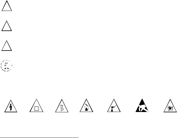
Safety symbols
Potential sources of danger in this description are identified by means of the following symbols:
! |
Danger |
This symbol calls attention to a situation that could cause serious |
|||||
injury or death to a person. |
|||||||
|
|
|
|
|
|
This symbol calls attention to a situation that could cause serious |
|
|
|
|
|
|
|
||
! |
Warning |
||||||
injury to a person. |
|||||||
|
|
|
|
|
|
This symbol calls attention to a situation that could damage or |
|
|
|
|
|
|
|
||
! |
Caution |
||||||
destroy hardware or software. |
|||||||
|
|
|
|
|
|
This symbol identifies useful informations. |
|
|
|
|
|
|
|
||
|
|
|
|
|
|
||
|
|
|
|
|
|
|
|
|
|
|
|
|
|
|
|
|
|
|
|
|
|
|
|
Further symbols for defining the source of danger in greater detail1:
|
|
|
|
|
|
|
|
|
|
|
|
|
|
|
|
|
|
|
|
|
|
|
|
|
|
|
|
|
|
|
|
|
|
|
|
|
|
|
|
|
|
|
|
|
|
|
|
|
|
|
|
|
|
|
|
Electricity |
Weight |
Heat |
Fire |
Chemicals |
ESD* |
Laser |
|||||||
* Electrostatic discharge
1.These symbols are not usually used in the manual. They’re an explanation of the symbols that can be depicted on the systems.
A31003-K16-X001-3-7620, 07/99 |
1-1 |
Hicom 100 E Version 2.1, Service manual |
Important Information
Safety information
1.1.1Safety information: Danger
●Do not open the power supply. The device may only repaired by authorized personnel.
Opening the device and tampering with it can endanger your life.
●Before applying power to the system or connecting extensions, ensure that the system is correctly carthed.
Never operate the equipment with protective earthing conductor disconnected!
●Voltages above 30 V AC (alternating current) or 60 V DC (direct current) are dangerous.
●If the power cable appears to be damaged, replace it immediately.
●Immediately replace any damaged safety equipment (covers, labels and protective cables).
●If the maintenance work requires the power supply of the system to be shut down:
–Use the shut-off switch to disconnect the system from the power supply circuit, and secure the shut-off device mechanically so that it cannot be used by other persons.
–Affix the information "DO NOT OPERATE" to the disconnect device.
A disconnect device can be a shut-off switch (main switch) or protective switch (fuse/ automatic cut out).
–Before starting any work on the installation, establish the location of the disconnect device.
●If you are performing work on circuits with hazardous voltages, always work together with a partner who is familiar with the location of the switch for the power supply.
●Always ensure adequate insulation when touching powered circuits.
●Ensure that the installation is not powered by an additional power supply, or that it is protected via an additional fuse or an additional main switch.
●Before starting any work, check whether the corresponding circuits are still on power. Never take it for granted that all circuits have reliably been disconnected from the power supply when a fuse or a main switch has been switched off.
●During a thunderstorm, you should not connect or remove telephone lines and PCB boards.
●Expect to encounter leakage current from the telecommunication network.
●Ensure that, whenever work is carried out on an open installation, the installation is never left unsupervised.
|
A31003-K16-X001-3-7620, 07/99 |
1-2 |
Hicom 100 E Version 2.1, Service manual |
Important Information
Safety information
1.1.2Safety information: Warning
●There is the risk of an explosion if the Nickel Cadmium Batteryis not replaced correctly. The lithium battery must be replaced only by the same or equivalent types recommended by the manufacturer.
●Be aware of additional dangers with low voltages and large cross-sections. Cables with a large cross-section generally have lower voltages, although the current strengths are higher. This results in particular risks, e.g. in the event of short circuits.
●When working on the installations, never wear loose clothing and always tie back long hair.
●Never wear jewellery, metal watch straps or for instance metal fittings and rivets on items of clothing. There is a risk of injury and short circuit.
●The surface of a mirror is conductive! Never touch powered circuits with a mirror; you might injure yourself and/or at least cause short-circuit damage.
●Always wear the necessary eye protection whenever appropriate.
●Always wear a protective helmet where falling objects might injure you.
●Always disconnect the power supply when you are working directly next to a power supply unit or direct current converter, unless the work instructions expressly permit you to work without having to shut off the power.
●Never try to lift heavy objects without assistance.
●In case of laser radiation: do not stare into the beam.
A31003-K16-X001-3-7620, 07/99 |
1-3 |
Hicom 100 E Version 2.1, Service manual |
Important Information
Safety information
1.1.3Safety information: Caution
●Check the set nominal voltage of the installation (operating instructions and type plate).
●As long as the power supply is switched on, always observe the greatest caution when performing measurements on powered components and maintenance work on plug-in cards,
PC boards and covers.
●To protect against the electrostatic discharge (ESD):
–Always wear the wristband before performing any work on PCB boards and modules.
–Only transport PC boards in suitable protective packaging.
–Always place PC boards on a grounded conducting base, and do not process the PC boards anywhere else.
–Only use grounded soldering irons.
●Only use tools and testers suitable for the job. Do not use broken tools and testers, inspect them regularly.
●Find out the location of the main switch for the power supply of the system. Follow the appropriate instructions.
●Install cables in such a way that they do not pose an accident risk (i.e. so that they do not trip anybody up) and also so that they are not damaged.
|
A31003-K16-X001-3-7620, 07/99 |
1-4 |
Hicom 100 E Version 2.1, Service manual |
Important Information
Safety information
1.1.4General information
●If the installation is brought into the operating premises from a cold environment, condensation may occur. Wait until the temperature of the installation has adjusted to the ambient temperature and until the installation is absolutely dry before you start it up.
●Before starting wall assembly, check whether the load-bearing capacity of the wall is adequate, e.g. in the event of plasterboard walls.
●When maintenance work has been completed, always re-install all safety equipment in the right place.
●Check your tools regularly. Only use intact tools.
●Close the doors after test and maintenance work has been completed.
●All cables and lines which leave a system cabinet must be screened at least between the connection point in the cabinet and the point at which the cable leaves the cabinet. Use a clip and pressure screw to contact all screen fabric to the cabinet outlet. This is also applicable for permanently connected service equipment.
●Connect all cables only to the specified connection points.
●Do not install any external modems in the installation cabinets.
●Do not allow readily flammable materials to be stored near the installation or in the installation room.
●Ensure good lighting at the workplace.
●Untidiness at the workplace involves the risk of injuries.
A31003-K16-X001-3-7620, 07/99 |
1-5 |
Hicom 100 E Version 2.1, Service manual |
Important Information
Safety information
1.1.5Behaviour in emergencies
●In the event of accidents, remain calm and considered.
●Always switch off the power supply before you touch an accident victim.
●If you are not able to immediately switch off the power supply, only touch the victim with non-conducting materials (e.g. a broom handle made of wood), and first of all try to isolate the victim from the power supply.
●You must be familiar with first-aid principles in the event of electricity injuries. An urgent need in such emergencies is fundamental knowledge of the various methods of resuscitation if the victim has stopped breathing or if the victim’s heart is no longer beating, as well as first aid for treating burns.
●If the victim is not breathing, immediately perform mouth-to-mouth or mouth-to-nose resuscitation.
●If you have appropriate training, immediately perform heart massage if the victim’s heart is not beating.
●Immediately call an ambulance or the emergency doctor. Provide the following information in the following sequence:
–Where did the accident take place?
–What has happened?
–How many injured?
–What type of injuries?
–Wait for queries.
1.1.6Accident reporting
●Immediately report all accidents, "near accidents" and potential sources of danger to your manager.
●Report all electrical shocks, no matter how small.
|
A31003-K16-X001-3-7620, 07/99 |
1-6 |
Hicom 100 E Version 2.1, Service manual |
Important Information
Data protection and data security
1.2Data protection and data security
This system also processes and uses personal data, e.g. for call charge metering purposes, the displays and for recording user data.
In Germany, the processing and use of such personal data are subject to various regulations, including the regulations of the Federal Data Protection Law (Bundesdatenschutzgesetz =
BDSG). For other countries, please follow the appropriate national laws.
The aim of data protection is to protect the rights of individuals being affected by use of his personal data.
In addition, the aim of data protection is to ensure that data are not corrupted when processed and that one’s own interests and the interests of other parties which need to be protected are not affected.
Members of Siemens and Siemens Rolm staff are required to observe business and data secrecy as a result of the company’s work rules.
In order to ensure that the statutory requirements during service - whether during "on-site service" or during "tele service" - are consistently met, you should always observe the following rules. You will not only maintain the interests of your/our customers, you will also avoid personal consequences.
Contribute to maintain data protection and data security with your conscious action:
●Ensure that only appropriately authorized persons have access to customer data.
●Take full advantage of all options of allocating passwords; do not inform unauthorized persons of passwords, e.g. by means of a written note.
●Ensure that no unauthorized person is able to process (store, modify, transmit, disable, delete) or use customer data in any way.
●Prevent unauthorized persons from gaining access to data media, e.g. on backup disks or protocol printouts. This is applicable for service calls as well as for storage and transport.
●Ensure that data media which are no longer required are completely destroyed. Ensure that no papers remain generally available.
Work together with your contacts of the customer: This creates mutual confidence and reduces your own workload.
A31003-K16-X001-3-7620, 07/99 |
1-7 |
Hicom 100 E Version 2.1, Service manual |
Important Information
Data protection and data security
|
A31003-K16-X001-3-7620, 07/99 |
1-8 |
Hicom 100 E Version 2.1, Service manual |
System data
General system description
2 System data
2.1General system description
The Hicom 108/112/118 systems belonging to the Hicom 100 E product family are compact, digital, Euro-ISDN-compatible telephone systems suitable for analogue and digital network access and for analogue and digital terminals. The basic configuration of each system can be expanded and supplemented in different ways. See Figure 2-2 (Hicom 108), Figure 2-3 (Hicom 112), Figure 2-4 (Hicom 118).
The Hicom 108/112/118 systems are of flatpack design, i.e. without a backplane. All basic functions are incorporated on the motherboard (see Figure 3-4). The systems have plastic housings consisting of base, intermediate section, and cover. The Hicom 118 has an additional intermediate frame to accommodate system expansions. The housing sections are held together by easily released latches.
The system expansions are of the plug-in type. The Hicom 108 has 1 slot (for analogue trunk or S0 line modules), the Hicom 112 has 2 slots (for analogue trunk and S0 line modules), and the Hicom 118 has 4 slots for further system expansions with line and subscriber modules.
The function expansions (optional) are attached with their own housings to the basic housing.
The power supply (PSU/UPS) is also attached mechanically and electrically to the basic housing and is additionally secured by screws.
The integral main distribution frame is part of the basic housing. Plug-in connectors (terminal blocks) render the line network easily separable from the system cards.
A31003-K16-X001-3-7620, 07/99 |
2-1 |
Hicom 100 E Version 2.1, Service manual |

System data
Hardware overview
2.2Hardware overview
|
|
Hicom 100 E |
|
|
|
|
|
108 |
123 |
N |
N |
|
|
PQRSTUVWXYZ |
|||
|
|
|
ABCDEF |
|
|
Analogue |
|
456 |
|
||
|
ABCDEF |
|
|||
|
7PQRSTUV89 |
|
|||
|
|
|
GHIJKLMNO |
|
|
|
|
|
GHI MNO |
|
|
S0 tnk./ |
tnk. |
112 |
00 |
|
|
|
|
0 |
|||
118 |
|
|
|||
extensions |
|
|
|
|
|
|
|
optiset E memory with |
optiset E advance plus |
||
Hicom 300 |
|
|
|||
|
|
optiset expansion |
|
with optiset expansion |
|
U |
|
interface |
ABCDEF |
|
ABC |
||
|
GHI MDEFNO |
||
|
P0/E |
|
123JKL |
|
|
GHIQRSTUVWXYZMNO |
|
|
|
|
P456 |
|
|
|
PQRSTUV |
|
|
|
789 |
|
|
|
00 |
|
|
|
0 |
|
|
optiset E advance plus |
optiset E memory |
||
|
|
|
- optiset E entry |
|
|
|
|
|
- optiset E advance |
||
|
|
profiset |
- optiset standard |
|
|
Voice |
Group 3 fax |
- optiset memory |
|
||
|
|
||||
terminal |
|
|
|
|
gigaset |
|
|
|
|
|
|
|
|
|
Entrance telephone |
megaset |
|
|
|
|
|
||
gigaset i |
a/b interface |
Personal computer |
Call charge computer/PC |
|
V.24 interface |
||
or printer |
Group 4 fax
Figure 2-1 Connection options supported within system environment
A31003-K16-X001-3-7620, 07/99
2-2 |
Hicom 100 E Version 2.1, Service manual |
System data
Documentation
2.3Documentation
|
|
Designation |
Item code number |
|
|
|
|
|
Hicom 100 E Service Manual (German) |
A31003-K16-X-*-20 (up to SW 2.0.1+) |
|
|
Hicom 100 E Service Manual (Dutch) |
A31003-K16-X-*-5420 |
|
|
Hicom 100 E Service Manual (Italian) |
A31003-K16-X-*-7220 |
|
|
Hicom 100 E Service Manual (Finnish) |
A31003-K16-X-*-7320 |
|
|
Hicom 100 E Service Manual (English) |
A31003-K16-X-*-7620 |
|
|
Hicom 100 E Service Manual (French) |
A31003-K16-X-*-7720 |
|
|
Hicom 100 E Service Manual (Spanish) |
A31003-K16-X-*-7820 |
|
|
Hicom 100 E Service Manual (Portuguese) |
A31003-K16-X-*-7920 |
|
|
|
|
|
|
Hicom 100 E Electronic Service Manual |
P31003-K16-X001-*-20 |
|
|
|
|
(up to SW 2.1) |
|
|
|
German and other languages |
|
|
|
|
|
Hicom 100 E Customer Datasheets |
A31003-K16-X-*-K6 |
|
|
|
|
German and other languages |
|
|
|
|
|
Service Instructions for |
A31003-E8000-A100-*-20 |
|
|
telephones, adapters, add-on units: |
German and other languages |
|
|
optiset E entry |
|
(see above) |
|
optiset E basic |
|
|
|
optiset E standard |
|
|
|
optiset E advance |
|
|
|
optiset E advance plus |
|
|
|
optiset E memory |
|
|
|
optiset E key module (add-on units) |
|
|
|
optiset E analogue adapter |
|
|
|
optiset E data adapter |
|
|
|
optiset E ISDN adapter |
|
|
|
optiset E phone adapter |
|
|
|
optiset E acoustic adapter |
|
|
|
optiset E distance adapter S |
|
|
|
optiset E distance adapter M |
|
|
|
|
|
|
|
User Manual (SW 2.0.1+): |
A31003-K3000-B341-*-19 |
|
|
System Support/Administration |
German and other languages |
|
|
|
|
(see above) |
|
|
|
|
|
User Manual (SW 2.0.2): |
A31003-K16-B455-*-19 |
|
|
System Support/Administration |
German and other languages |
|
|
|
|
(see above) |
|
|
|
|
|
Table 2-1 |
Documentation |
|
A31003-K16-X001-3-7620, 07/99 |
2-3 |
||
Hicom 100 E Version 2.1, Service manual |
|||
System data
System types
|
Designation |
Item code number |
|
|
|
User Manual (SW 2.1) |
A31003-K16-B546-*-19 |
|
System Support/Administration |
German and other languages |
|
|
|
(see above) |
|
|
|
Table 2-1 |
Documentation |
|
Documentation is available from your Dealer. |
|
|
2.4System types
The systems are available in the following configurations:
Hicom 108 with one slot, 2 UP0/E and 4 a/b extension interfaces (see Figure 2-2)
Hicom 112 with two slots, 4 UP0/E and 4 a/b extension interfaces (see Figure 2-3) Hicom 118 with four slots, 6 UP0/E and 4 a/b extension interfaces (see Figure 2-4) Nameplate on the housing base near the main distribution frame
A distinction is made between the following components:
●Basic system, motherboard with V.24 interface via mini-DIN connector and optional EXM/
MPPI (external music on hold)
●PSU1 power supply unit for Hicom 108 and 112 (see Section 3.8)
UPS1 uninterruptible power supply for Hicom 112 (see Section 3.8)
PSU2 power supply unit for Hicom 118 (see Section 3.8)
UPS2 uninterruptible power supply for Hicom 118 (see Section 3.8)
●System expansions
The modular design permits almost any slot assignments (see Table 3-12).
SLAS subscriber line analogue with 4, 8 or 16 a/b interfaces
SLU 8 subscriber line UP0/E with 8 UP0/E interfaces
STLS subscriber/trunk line S0 with 4 S0 interfaces or 2 S0 interfaces
TLA trunk line analogue with 2, 4 or 8 analogue trunk interfaces
●Function expansions (see Section 3.6)
ALUM power failure transfer with 4 transfer options for analogue lines Fax/DDI with announcement (DTMF)
GEE call-charge pulse recognition for 4 analogue trunk interfaces SIB serial interface board (optional V.24 interface)
STRB control relay module with 4 control inputs and 4 control outputs STBG4 current limiting module for France
WS48/ÜFS analogue DDI trunk for Austria EXM/MPPI - module for MOH
|
A31003-K16-X001-3-7620, 07/99 |
2-4 |
Hicom 100 E Version 2.1, Service manual |

System data
Hicom 108 system overview
The MDF (main distribution frame) (see Section 3.9) expands automatically with the system, since each expansion provides the necessary interfaces. Any space that may be required for future function expansions must be taken into account in the initial plans.
2.5Hicom 108 system overview
Cover/MDF |
Basic system |
|
|
|
|
|
|
|
|
|
|
|
|
|
|
|
|
|
|
|
|
|
|
Hicom 108
PSU1
System expansion 1
Plug in and secure (screw)
1 ... 4
Plug in
Function expansions
Figure 2-2 Hicom 108 structural concept
Slot 1 for system expansions:
Analogue (TLA2) or S0 (STLS2) trunk module (see Table 3-12)
A31003-K16-X001-3-7620, 07/99 |
2-5 |
Hicom 100 E Version 2.1, Service manual |
 Loading...