


SINUMERIK 840C Software Version 1 to 6
Planning Guide |
09.2001 Edition |
Interface Description
Part 1: Signals
Manufacturer Documentation

SINUMERIK 840C Software Version 1 to 6 Interface Description Part 1: Signals
Planning Guide
Valid for:
Control SINUMERIK 840C/CE |
Drive SIMODRIVE 611-D |
|
Standard export version |
||
|
||
Software Version |
Software Version |
|
|
|
|
1.x |
|
|
|
|
|
2.x |
|
|
|
|
|
3.x |
1.x |
|
|
|
|
4.x |
2.x |
|
|
|
|
5.x |
3.x |
|
|
|
|
6.x |
4.x |
09.2001 Edition

SINUMERIK® documentation
Printing history
Brief details of this edition and previous editions are listed below.
The status of each edition is shown by the code in the ”Remarks” column.
Status code in ”Remarks” column:
A. . . New documentation
B. . . Unrevised reprint with new Order No.
C. . . Revised edition with new status.
If factual changes have been made on the page since the last edition, this is indicated by a new edition coding in the header on that page.
Edition |
Order No. |
Remarks |
11.92 |
6FC5197-0AA00-1BP0 |
A |
06.93 |
6FC5197-2AA00-0BP0 |
C |
12.93 |
6FC5197-3AA00-0BP0 |
C |
10.94 |
6FC5197-4AA00-0BP0 |
C |
03.95 |
6FC5197-4AA00-0BP1 |
C |
09.95 |
6FC5197-5AA00-0BP0 |
C |
04.96 |
6FC5197-5AA00-0BP1 |
C |
08.96 |
6FC5197-5AA00-0BP2 |
C |
07.97 |
6FC5197-6AA00-0BP0 |
C |
01.99 |
6FC5197-6AA00-0BP1 |
C |
09.01 |
6FC5197-6AA00-0BP2 |
C |
This manual is included in the documentation available on CD-ROM (DOCONCD) |
||
Edition |
Order No. |
Remarks |
10.01 |
6FC5198-6CA00-0BG2 |
C |
Trademarks
SIMATIC®, SIMATIC HMI®, SIMATIC NET®, SIROTEC®, SINUMERIK® and SIMODRIVE® are trademarks of Siemens AG. All other product and system names are registered trademarks of their respective companies and must be treated accordingly.
For more information, refer to the Internet: http://www.ad.siemens.de/sinumerik
The publication was produced on the Siemens 5800 Office System.
The reproduction, transmission or use of this document or its contents is not permitted without express written authority. Offenders will be liable for damages. All rights, including created by patent grant or registration of a utility model or design, are reserved,
© Siemens AG 1992-2001
All Rights Reserved
Other functions not described in this documentation might be executable in the control. This does not, however, represent an obligation to supply such functions with a new control or when servicing.
We have checked that the contents of this publication agree with the hardware and software described herein. The information given in this publication is reviewed at regular intervals and any corrections that might be necessary are made in the subsequent printings. Suggestions for improvement are welcome at all times.
Subject to change without prior notice.
Order No. 6FC5197-6AA00-0BP2 |
Siemens-Aktiengesellschaft |
Printed in the Federal Republic of Germany |
|

Preliminary Remarks
Notes for the reader
This manual is intended for manufacturers of machine tools with SINUMERIK 840C. It describes the installation and cabling between control and machine as well as the signals between PLC and machine.
The SINUMERIK documentation falls into four groups:
•General Documentation
•User Documentation
•Manufacturer Documentation
•Service Documentation
The Manufacturer Documentation for the SINUMERIK 840C control is divided into the following parts:
•Instruction Manual
•Interface
Part 1: Signals
Part 2: Connection Conditions
•Planning Guide PLC 135 WB/WB 2/WD
•Function Macros
•Function Blocks
Package 0: Basic Functions Package 1: Tool Management Package 4/5: Computer Link Package 7: Code Carrier
Package 8: PLC-controlled data input and output
Further SINUMERIK publications apply to all SINUMERIK controls (e.g. Universal Interface, Measuring Cycles, CL 800 Cycle Language).
Consult your local Siemens office for further details.
Technical notes
•In the signal charts, the interface signals are represented by thick lines. Thin lines represent signals symbolically or refer to internal messages.
•Signals designated with a * are so-called inverse signals, i.e. a 0 signal has an effect rather than a 1 signal (e.g. *TEMPERATURE ERROR).
Where order numbers are given with a as placeholder, this indicates that there are several versions available of one component.
This Guide is valid up to and including Software Version 6!
Safety-related guidelines
WARNING
Hazardous voltages are present in this electrical equipment during operation.
Persons who are not qualified should not be allowed to handle the equipment/system. Non-compliance with the warnings can result in severe personal injury or damage to property. Only qualified personnel familiar with the installation, construction, commissioning and operation of the equipment should be allowed to work on this equipment/system
Qualified personnel
WARNING
Qualified personnel as referred to in the safety guidelines (contained in the documentation or on the product labels) are persons who have the following qualifications:
•Are trained and authorized to energize, de-energize, clear, ground and tag circuits and equipment in accordance with established safety practices.
•Are trained in the proper care, use and repair of protective equipment in accordance with established safety practices.
•Are trained in the use of electrostatic sensitive components and modules.
•Operating personnel who have been trained to work with automation equipment and are conversant with the contents of the operating and/or programming instructions in as far as they are connected with the actual operation of the plant.
Anyone engaged in configuring, installation, commissioning and repair of the control must be familiar
with the relevant documentation.
Danger notices
The notices and guidelines that follow are intended to ensure personal safety, as well as protect the product and connected equipment and machines against damage.
The safety notices and warnings for protection against loss of life (of the users or service personnel) or for protection against damage to property are highlighted in this document by the terms defined here. The terms used in this document and marked on the equipment itself have the following significance:
DANGER
For the purpose of this document and the product labels, "Danger" indicates that death, severe personal injury or substantial property damage will result if proper precautions are not taken.
WARNING
For the purpose of this document and the product labels, "Warning" indicates that death, severe personal injury or substantial property damage can result if proper precautions are not taken.
CAUTION
For the purpose of this document and the product labels, "Caution" indicates that minor personal injury or property damage can result if proper precautions are not taken.
CAUTION
This warning notice (without warning triangle) means that a material damage can result if the appropriate precautions are not taken.
NOTICE
This warning notice means that an undesired event or an undesired state can result if the appropriate notices are not observed.
”Note" contains important information
about the product, its operation or a part of the document
to which special attention is drawn.
Proper usage
•The equipment/system or the system components may only be used for the applications described in the catalog or the technical description, and only in combination with the equipment, components and devices of other manufacturers as far as this is recommended or permitted by Siemens.
•The product described has been developed, manufactured, tested and the documentation compiled in keeping with the relevant safety standards. Consequently, if the described handling instructions and safety guidelines described for planning, installation, proper operation and maintenance are adhered to, the product, under normal conditions, will not be a source of danger to property or life.
Active and passive faults in automation equipment
•Depending on the particular task for which the electronic automation equipment is used, both active as well as passive faults can result in a dangerous situation. For example, in drive control, an active fault is generally dangerous because it can result in unauthorized starting of the drive. On the other hand, a passive fault in a signalling function can result in a dangerous operating state not being reported to the operator.
•This differentiation of the possible faults and their classification into dangerous and nondangerous faults, depending on the particular task, is important for all safety considerations in respect to the product supplied.
WARNING
Wherever a fault in automation equipment can result in severe personal injury or substantial damage to property, i.e. wherever a dangerous fault can occur, additional external measures must be taken or equipment provided to ensure or force safe operating conditions, even in the event of a fault (e.g. by means of independent limit monitors, mechanical interlocks, etc.).
Guidelines for the planning of the product
The product generally forms a part of larger systems or plants. These guidelines are intended to help integrate the product into its environment without it constituting a source of danger.
The following requires particular
Even when a high degree of safety has been included in the design of |
automation equipment, e.g. by means of multichannel configuration, it is |
still imperative that the instructions contained in the documentation be |
exactly adhered to. Incorrect handling can render ineffective the |
preventive measures incorporated in the system to protect against |
dangerous faults or new sources of danger might be created. |
Further notes
If measurement or testing work is to be carried out on an active item of equipment, the rules and regulations contained in the "VBG 4.0 Accident prevention regulations" of the German employers liability assurance association (Berufsgenossenschaften) must be observed. Particular attention is drawn to paragraph 8 "Permissible exceptions when working on live parts". Only suitable electrical tools should be used.
WARNING
•Repairs to equipment supplied by us may only be carried out by
Siemens service personnel or repair shops authorized by Siemens to carry out such repairs. For replacement purposes, use only parts or components that are contained in the spare parts list. Unauthorized opening of equipment and improper repairs can result in loss of life or severe personal injury as well as substantial property damage.
•Before opening the equipment, always remove the power plug or open the disconnecting switch.
•When replacing fuses, only use the fuse types specified.
•Do not throw batteries into an open fire and do not carry out any soldering work on batteries (danger of explosion). Maximum ambient temperature 100°C. Batteries should not be opened or recharged. Make sure that the same type is used when replacing batteries.
•Batteries must always be disposed of properly.
•The following points require attention when using monitors: Improper handling, especially the readjustment of the high voltage or fitting of another tube type can result in excessive X-ray radiation from the unit. The license to operate such a modified unit automatically lapses and the unit must not be operated at all.
General Overview |
1 |
|
|
|
|
|
|
|
Assigned Areas |
2 |
|
|
|
|
|
|
|
Description of Basic Signals FY 0 ... FY 24 |
3 |
|
|
|
|
NCK Channel/PLC Interface (DB 10 ... DB 13) as from SW 4 DB 15 |
|
|
4 |
||
|
|
|
Spindle/PLC Interface (DB 31) |
|
|
5 |
||
|
|
|
Axis/PLC Interface (DB 32 / DB 29) |
|
|
6 |
||
|
|
|
Data Transfer PLC/NC (DB 36 / DB 29) |
|
|
7 |
||
|
|
|
|
|
|
Control of Data Transfer (DB 37) |
8 |
|
|
|
|
|
|
|
Operator Panel Interface (DB 40) |
9 |
|
|
|
|
|
|
|
Command Channel (DB 41) |
10 |
|
|
|
|
Communication Area NC/PLC Interface (DB 48) |
|
|
11 |
||
|
|
|
Display Programs for PLC Data and Messages |
|
|
up to SW 2 |
12 |
|
|
|
|
Display of PLC Alarms, Messages |
|
|
and Dialogs as from SW 3 |
13 |
|
|
|
|
|
|
|
PLC Machine Data (PLC MD) |
14 |
|
|
|
|
|
|
|
Data Blocks Installed for Users (DB 66 ... DB 71) |
15 |
|
|
|
|
|
|
|
Alphabetical List of Signal Names |
16 |
|
|
|
|
|
|
|
Terms and Abbreviations |
17 |
|
|
|
|
Contents
1 |
General Overview . . . . . . . . . . . . . . . . . . . . . . . . . . . . . . . . . . . . . . |
1±1 |
1.1 |
Control structure . . . . . . . . . . . . . . . . . . . . . . . . . . . . . . . . . . . . . . . |
1±1 |
1.1.1 |
Components of SINUMERIK 840C . . . . . . . . . . . . . . . . . . . . . . . . . . . |
1±3 |
1.1.2 |
NCK area . . . . . . . . . . . . . . . . . . . . . . . . . . . . . . . . . . . . . . . . . . . . |
1±6 |
1.1.3 |
MMC area . . . . . . . . . . . . . . . . . . . . . . . . . . . . . . . . . . . . . . . . . . . . |
1±8 |
1.1.4 |
PLC area . . . . . . . . . . . . . . . . . . . . . . . . . . . . . . . . . . . . . . . . . . . . . |
1±8 |
1.1.5 |
PLC-machine interface . . . . . . . . . . . . . . . . . . . . . . . . . . . . . . . . . . . |
1±10 |
1.2 |
PLC program . . . . . . . . . . . . . . . . . . . . . . . . . . . . . . . . . . . . . . . . . . |
1±11 |
1.2.1 |
Tasks of the PLC program . . . . . . . . . . . . . . . . . . . . . . . . . . . . . . . . |
1±11 |
1.2.2 |
Structure of the PLC program . . . . . . . . . . . . . . . . . . . . . . . . . . . . . . |
1±11 |
1.2.2.1 |
PLC operating system . . . . . . . . . . . . . . . . . . . . . . . . . . . . . . . . . . . . |
1±12 |
1.2.2.2 |
Difference between dynamic and static signals . . . . . . . . . . . . . . . . . . |
1±13 |
1.2.3 |
Reaction to interrupt and alarm signals . . . . . . . . . . . . . . . . . . . . . . . . |
1±13 |
2 |
Assigned Areas . . . . . . . . . . . . |
. . . . . . . . . . . . . . . . . . . . . . . . . . |
. |
2±1 |
2.1 |
Flags, data formats . . . . . . . . . . . |
. . . . . . . . . . . . . . . . . . . . . . . . . . |
. |
2±1 |
2.2 |
Class DB/DX data blocks . . . . . |
. . . . . . . . . . . . . . . . . . . . . . . . . . . |
. |
2±2 |
2.3 |
Function blocks . . . . . . . . . . . . . |
. . . . . . . . . . . . . . . . . . . . . . . . . . . |
|
2±5 |
2.3.1 |
Class FB function blocks . . . . . . . |
. . . . . . . . . . . . . . . . . . . . . . . . . . |
. |
2±5 |
2.3.2 |
Class FX function blocks . . . . . . . |
. . . . . . . . . . . . . . . . . . . . . . . . . . |
. |
2±9 |
2.4 |
Basic signals . . . . . . . . . . . . . . . . |
. . . . . . . . . . . . . . . . . . . . . . . . . . |
|
2±11 |
2.4.1 |
Assignment of DB 1 (diagnostics) (Section 3.6) . . . . . . . . . . . . . . . |
. . . |
2±13 |
|
2.4.2 |
High-speed data channels (as from SW 4) . . . . . . . . . . . . . . . . . . . |
. . |
2±16 |
|
2.4.2.1 |
DB 2 Configuration DB . . . . . . . . |
. . . . . . . . . . . . . . . . . . . . . . . . . . . |
|
2±16 |
2.4.2.2 |
DB 3 Data transfer areas . . . . . . |
. . . . . . . . . . . . . . . . . . . . . . . . . . |
. |
2±17 |
2.5 |
NCK/PLC interface . . . . . . . . . . . . |
. . . . . . . . . . . . . . . . . . . . . . . . . . |
|
2±18 |
2.5.1 |
Channel-specific signals . . . . . . . |
. . . . . . . . . . . . . . . . . . . . . . . . . . |
. |
2±18 |
2.5.1.1 |
Signals to NCK channel (DB 10 ... |
DB 13, as from SW 4 DB 15) |
. . . . . |
2±18 |
2.5.1.2 |
Signals from NCK channel (DB 10... |
DB 13, as from SW 4 DB 15) |
. . . . |
2±20 |
2.5.1.3 |
Auxiliary functions from NCK channel (DB 10 ... DB 13, |
|
|
|
|
as from SW 4 DB 15) . . . . . . . . . |
. . . . . . . . . . . . . . . . . . . . . . . . . . . |
|
2±21 |
2.5.1.4 |
Axis-specific Safety Integrated signals (DB28) (as from SW 5.4) . . |
. . . . |
2±29 |
|
2.5.1.5 |
Axis-specific GI signals (DB 29) 1) |
. . . . . . . . . . . . . . . . . . . . . . . . . . |
. |
2±30 |
2.5.1.6 |
Axis-specific 611-D signals (DB 29) . . . . . . . . . . . . . . . . . . . . . . . . |
. . |
2±31 |
|
2.5.1.7 |
M signals (DB 30) decoded according to list . . . . . . . . . . . . . . . . . . |
. . |
2±32 |
|
2.5.2 |
Spindle-specific signals (DB 31) . . |
. . . . . . . . . . . . . . . . . . . . . . . . . . |
. |
2±33 |
2.5.2.1 |
Signals from spindle . . . . . . . . . . . |
. . . . . . . . . . . . . . . . . . . . . . . . . . |
|
2±33 |
2.5.2.2 |
Signals to spindle . . . . . . . . . . . . . |
. . . . . . . . . . . . . . . . . . . . . . . . . . |
|
2±33 |
2.5.2.3 |
Spindle-specific GI signals from spindle . . . . . . . . . . . . . . . . . . . . . |
. . |
2±34 |
|
2.5.2.4 |
Spindle-specific GI signals to spindle . . . . . . . . . . . . . . . . . . . . . . . |
. . |
2±34 |
|
2.5.2.5 |
Star-delta switchover, 611D . . . . . |
. . . . . . . . . . . . . . . . . . . . . . . . . . |
. |
2±35 |
2.5.3 |
Axis-specific signals (DB 32) . . . . |
. . . . . . . . . . . . . . . . . . . . . . . . . . |
. |
2±37 |
2.6 |
Data transfer interface . . . . . . . . |
. . . . . . . . . . . . . . . . . . . . . . . . . . . |
|
2±39 |
2.6.1 |
Data transfer PLC/NCK (DB 36) . . |
. . . . . . . . . . . . . . . . . . . . . . . . . . |
. |
2±39 |
2.6.2 |
Control of data transfer (DB 37) . . |
. . . . . . . . . . . . . . . . . . . . . . . . . . |
. |
2±40 |
2.7 |
Operator panel/PLC interface . . . . |
. . . . . . . . . . . . . . . . . . . . . . . . . . |
. |
2±41 |
2.7.1 |
Key signals from operator panel (DB 40) . . . . . . . . . . . . . . . . . . . . |
. . |
2±41 |
|
2.7.2 |
Display dialog line (DB 40) . . . . . |
. . . . . . . . . . . . . . . . . . . . . . . . . . |
. |
2±43 |
2.7.3 |
Menu selection (DB 40) . . . . . . . . . . |
. . . . . . . . . . . . . . . . . . . . . . . . . |
2±44 |
2.7.4 |
Cursor data (DB 40) . . . . . . . . . . . . |
. . . . . . . . . . . . . . . . . . . . . . . . . |
2±45 |
2.7.5 |
User key signals (DB 40) . . . . . . . . . |
. . . . . . . . . . . . . . . . . . . . . . . . . |
2±46 |
2.7.6 |
Command channel interface (DB 41) |
. . . . . . . . . . . . . . . . . . . . . . . . . |
2±48 |
2.8 |
General interface NCK/PLC . . . . . . . |
. . . . . . . . . . . . . . . . . . . . . . . . . |
2±50 |
2.8.1 |
Signals to/from NCK (DB 48) . . . . . . |
. . . . . . . . . . . . . . . . . . . . . . . . . |
2±50 |
2.9 |
PLC messages (DB 58) . . . . . . . . . . . |
. . . . . . . . . . . . . . . . . . . . . . . . |
2±52 |
2.9.1 |
Softkey function calls DB 59 . . . . . . . |
. . . . . . . . . . . . . . . . . . . . . . . . |
2±56 |
2.10 |
PLC machine data . . . . . . . . . . . . . . . |
. . . . . . . . . . . . . . . . . . . . . . . |
2±57 |
2.11 |
Configuring distributed machine peripherals (DMP) . . . . . . . . . . . . . . . |
2±58 |
|
2.12 |
Set-up DBs for users . . . . . . . . . . . . . |
. . . . . . . . . . . . . . . . . . . . . . . |
2±68 |
2.12.1 |
Icon selection in the MMC (DB 66) . . . |
. . . . . . . . . . . . . . . . . . . . . . . . |
2±68 |
2.12.2 |
Internal machine control panel (DB 67) . . . . . . . . . . . . . . . . . . . . . . . . |
2±70 |
|
2.12.3 |
Data words for users (DB 68) . . . . . . |
. . . . . . . . . . . . . . . . . . . . . . . . |
2±70 |
2.12.4 |
Data bits for users (DB 71) . . . . . . . . . |
. . . . . . . . . . . . . . . . . . . . . . . |
2±71 |
2.13 |
Decoding list for M signals (DB 80 ... DB 83) . . . . . . . . . . . . . . . . . . . |
2±71 |
|
3 |
Description of Basic Signals FY 0... |
FY 24 . . . . . . . . . . . . . . . . . . . . |
3±1 |
3.1 |
PLC auxiliary signals . . . . . . . . . . . . . . |
. . . . . . . . . . . . . . . . . . . . . . . |
3±1 |
3.2 |
PLC ready signals . . . . . . . . . . . . . . . . . |
. . . . . . . . . . . . . . . . . . . . . . |
3±6 |
3.3 |
Signals for alarm-controlled machining . . . . . . . . . . . . . . . . . . . . . . . . |
3±7 |
|
3.4 |
NC ready signals . . . . . . . . . . . . . . . . . |
. . . . . . . . . . . . . . . . . . . . . . |
3±8 |
3.5 |
Individual signals . . . . . . . . . . . . . . . . . |
. . . . . . . . . . . . . . . . . . . . . . |
3±8 |
3.6 |
Diagnostics (DB 1) . . . . . . . . . . . . . . . |
. . . . . . . . . . . . . . . . . . . . . . . |
3±11 |
4 |
NCK Channel/PLC Interface (DB 10 ... |
DB 13, as from SW 4 DB 15) |
4±1 |
4.1 |
SINUMERIK 840C terms and structure . . . . . . . . . . . . . . . . . . . . . . . |
4±1 |
|
4.1.1 |
Channel . . . . . . . . . . . . . . . . . . . . . . . . |
. . . . . . . . . . . . . . . . . . . . . . |
4±1 |
4.1.2 |
Operating mode group . . . . . . . . . . . . |
. . . . . . . . . . . . . . . . . . . . . . . |
4±3 |
4.1.3 |
Channel-specific interface signal exchange . . . . . . . . . . . . . . . . . . . . . |
4±4 |
|
4.2 |
Signals to NCK channel . . . . . . . . . . . |
. . . . . . . . . . . . . . . . . . . . . . . |
4±7 |
4.2.1 |
Operating modes . . . . . . . . . . . . . . . . . |
. . . . . . . . . . . . . . . . . . . . . . |
4±7 |
4.2.2 |
Feedrate modification . . . . . . . . . . . . . |
. . . . . . . . . . . . . . . . . . . . . . . |
4±8 |
4.2.3 |
Program control . . . . . . . . . . . . . . . . . . |
. . . . . . . . . . . . . . . . . . . . . . |
4±10 |
4.2.4 |
General feed disable . . . . . . . . . . . . . . |
. . . . . . . . . . . . . . . . . . . . . . . |
4±20 |
4.2.5 |
Read-in disable . . . . . . . . . . . . . . . . . . |
. . . . . . . . . . . . . . . . . . . . . . |
4±22 |
4.2.6 |
NC Start disable . . . . . . . . . . . . . . . . . . |
. . . . . . . . . . . . . . . . . . . . . . |
4±23 |
4.3 |
Signals from NC channel . . . . . . . . . . . |
. . . . . . . . . . . . . . . . . . . . . . . |
4±23 |
4.3.1 |
Program commands . . . . . . . . . . . . . . |
. . . . . . . . . . . . . . . . . . . . . . . |
4±23 |
4.3.2 |
Select program control . . . . . . . . . . . . |
. . . . . . . . . . . . . . . . . . . . . . . |
4±30 |
4.3.3 |
Acknowledgements . . . . . . . . . . . . . . . |
. . . . . . . . . . . . . . . . . . . . . . . |
4±33 |
4.3.4 |
Ready signals . . . . . . . . . . . . . . . . . . . . |
. . . . . . . . . . . . . . . . . . . . . . |
4±35 |
4.4 |
Output of auxiliary functions and block information . . . . . . . . . . . . . . . . |
4±38 |
|
4.4.1 |
General . . . . . . . . . . . . . . . . . . . . . . . . |
. . . . . . . . . . . . . . . . . . . . . . |
4±38 |
4.4.2 |
Behaviour in different modes . . . . . . . |
. . . . . . . . . . . . . . . . . . . . . . . . |
4±39 |
4.4.3 |
Description of information signals . . . . |
. . . . . . . . . . . . . . . . . . . . . . . . |
4±40 |
4.4.4 |
T/H word routing . . . . . . . . . . . . . . . . . . |
. . . . . . . . . . . . . . . . . . . . . . |
4±45 |
4.4.5 |
TEACH IN . . . . . . . . . . . . . . . . . . . . . . |
. . . . . . . . . . . . . . . . . . . . . . |
4±48 |
4.5 |
Structure of program coordination . . . |
. . . . . . . . . . . . . . . . . . . . . . . . |
4±49 |
4.5.1 |
Alarms . . . . . . . . . . . . . . . . . . . . . . . . . . |
. . . . . . . . . . . . . . . . . . . . . |
4±49 |
4.5.2 |
NCK/PLC user interface . . . . . . . . . . . |
. . . . . . . . . . . . . . . . . . . . . . . |
4±50 |
4.5.3 |
PLC function blocks FX 38, FX 39 . . . |
. . . . . . . . . . . . . . . . . . . . . . . . |
4±51 |
5 |
Spindle/PLC Interface (DB 31) . . . . . . . . . . . . . . . . . . . . . . . . . . . . |
5±1 |
5.1 |
General . . . . . . . . . . . . . . . . . . . . . . . . . . . . . . . . . . . . . . . . . . . . . . |
5±1 |
5.2 |
Signals from spindle . . . . . . . . . . . . . . . . . . . . . . . . . . . . . . . . . . . . . |
5±3 |
5.3 |
Signals to spindle . . . . . . . . . . . . . . . . . . . . . . . . . . . . . . . . . . . . . . . |
5±12 |
5.4 |
Signals from following spindle to PLC, DB 31 for the GI function . . . . . . |
5±23 |
5.5 |
Signals from PLC to following spindle for GI function . . . . . . . . . . . . . . |
5±29 |
5.6 |
Interface signals for drive 611D (DB 29/DB31) . . . . . . . . . . . . . . . . . . |
5±33 |
6 |
Axis/PLC Interface (DB 32/DB 29) . . . . . . . . . . . . . . . . . . . . . . . . . . |
6±1 |
6.1 |
Signals from axis . . . . . . . . . . . . . . . . . . . . . . . . . . . . . . . . . . . . . . . |
6±2 |
6.2 |
Signals to axis . . . . . . . . . . . . . . . . . . . . . . . . . . . . . . . . . . . . . . . . . |
6±7 |
6.2.1 |
Signals for endlessly turning rotary axis . . . . . . . . . . . . . . . . . . . . . . . |
6±24 |
6.3 |
Signals from following axis to PLC, DB 29 . . . . . . . . . . . . . . . . . . . . . |
6±27 |
6.3.1 |
Axis-specific 611D signals (DB 29) . . . . . . . . . . . . . . . . . . . . . . . . . . . |
6±36 |
6.4 |
Structure of M decoding list (DB 30) . . . . . . . . . . . . . . . . . . . . . . . . . |
6±44 |
7 |
Data Transfer PLC/NC (DB 36) . . . . . . . . . . . . . . . . . . . . . . . . . . . . |
7±1 |
7.1 |
General . . . . . . . . . . . . . . . . . . . . . . . . . . . . . . . . . . . . . . . . . . . . . . |
7±1 |
7.1.1 |
Machine data (MD) . . . . . . . . . . . . . . . . . . . . . . . . . . . . . . . . . . . . . . |
7±2 |
7.1.2 |
Tool offsets . . . . . . . . . . . . . . . . . . . . . . . . . . . . . . . . . . . . . . . . . . . |
7±3 |
7.1.3 |
R parameters . . . . . . . . . . . . . . . . . . . . . . . . . . . . . . . . . . . . . . . . . . |
7±6 |
7.1.4 |
Zero offsets . . . . . . . . . . . . . . . . . . . . . . . . . . . . . . . . . . . . . . . . . . . |
7±8 |
7.2 |
Data transfer PLC initiative . . . . . . . . . . . . . . . . . . . . . . . . . . . . . . . . |
7±9 |
7.2.1 |
Structure with example . . . . . . . . . . . . . . . . . . . . . . . . . . . . . . . . . . . |
7±9 |
7.2.2 |
Description of job-specific interface signals . . . . . . . . . . . . . . . . . . . . . |
7±14 |
7.3 |
Data transfer NC initiative . . . . . . . . . . . . . . . . . . . . . . . . . . . . . . . . . |
7±16 |
8 |
Control of Data Transfer (DB 37) . . . . . . . . . . . . . . . . . . . . . . . . . . |
8±1 |
8.1 |
Description of interface signals . . . . . . . . . . . . . . . . . . . . . . . . . . . . . |
8±1 |
8.2 |
Signals for PLC initiative data transfer . . . . . . . . . . . . . . . . . . . . . . . . |
8±1 |
9 |
Operator Panel Interface (DB 40) . . . . . . . . . . . . . . . . . . . . . . . . . . |
9±1 |
9.1 |
Key signals from operator panel . . . . . . . . . . . . . . . . . . . . . . . . . . . . . |
9±2 |
9.1.1 |
Operating mode group (BAG) . . . . . . . . . . . . . . . . . . . . . . . . . . . . . . |
9±2 |
9.1.2 |
Softkey function signals . . . . . . . . . . . . . . . . . . . . . . . . . . . . . . . . . . |
9±3 |
9.2 |
Display dialog line . . . . . . . . . . . . . . . . . . . . . . . . . . . . . . . . . . . . . . |
9±8 |
9.3 |
Menu selection interface . . . . . . . . . . . . . . . . . . . . . . . . . . . . . . . . . . |
9±8 |
9.3.1 |
Softkey function calls DB 59 . . . . . . . . . . . . . . . . . . . . . . . . . . . . . . . |
9±24 |
9.3.1.1 |
Overview of softkey function calls from PLC . . . . . . . . . . . . . . . . . . . . |
9±26 |
9.3.1.2 |
Messages of softkey function calls . . . . . . . . . . . . . . . . . . . . . . . . . . . |
9±27 |
9.3.2 |
Signals from PLC to NCK . . . . . . . . . . . . . . . . . . . . . . . . . . . . . . . . . |
9±28 |
9.3.3 |
Signals from the NC to the PLC . . . . . . . . . . . . . . . . . . . . . . . . . . . . . |
9±31 |
9.4 |
Cursor data to PLC . . . . . . . . . . . . . . . . . . . . . . . . . . . . . . . . . . . . . . |
9±32 |
9.5 |
User key signals . . . . . . . . . . . . . . . . . . . . . . . . . . . . . . . . . . . . . . . . |
9±34 |
10 |
Command Channel (DB 41) . . . . . . . . . . . . . . . . . . . . . . . . . . . . . . |
10±1 |
10.1 |
General . . . . . . . . . . . . . . . . . . . . . . . . . . . . . . . . . . . . . . . . . . . . . . |
10±1 |
10.2 |
Signals in the command channel header . . . . . . . . . . . . . . . . . . . . . . . |
10±2 |
10.3 |
User interface signals . . . . . . . . . . . . . . . . . . . . . . . . . . . . . . . . . . . . |
10±3 |
10.4 |
Net data for command channel . . . . . . . . . . . . . . . . . . . . . . . . . . . . . |
10±7 |
10.4.1 |
Net data of the path dimension function . . . . . . . . . . . . . . . . . . . . . . . |
10±7 |
10.4.2 |
Net data for DIVISION function . . . . . . . . . . . . . . . . . . . . . . . . . . . . . . |
10±8 |
10.4.3 |
Net data for S EXTERNAL function . . . . . . . . . . . . . . . . . . . . . . . . . . |
10±9 |
10.4.4 |
Net data for the M19 tsr function (incremental spindle positioning) . . . . . |
10±11 |
10.4.5 |
Net data for the transformation function . . . . . . . . . . . . . . . . . . . . . . . |
10±13 |
10.4.6 |
Net data for coupled motion function . . . . . . . . . . . . . . . . . . . . . . . . . |
10±14 |
10.4.7 |
Net data of the ºTemperature compensationº function . . . . . . . . . . . . . |
10±16 |
10.4.8 |
Net data of ºRead/write IKA dataº function . . . . . . . . . . . . . . . . . . . . . |
10±18 |
10.4.9 |
Net data of ºTravel against fixed stopº function . . . . . . . . . . . . . . . . . . |
10±25 |
10.5 |
Error codes, general errors . . . . . . . . . . . . . . . . . . . . . . . . . . . . . . . . |
10±28 |
10.6 |
Error codes, function-related . . . . . . . . . . . . . . . . . . . . . . . . . . . . . . . |
10±29 |
10.6.1 |
Errors, function 1, path dimension, static . . . . . . . . . . . . . . . . . . . . . . . |
10±29 |
10.6.2 |
Errors with function 2, division increment . . . . . . . . . . . . . . . . . . . . . . |
10±30 |
10.6.3 |
Errors with function 3, S external . . . . . . . . . . . . . . . . . . . . . . . . . . . . |
10±31 |
10.6.4 |
Errors with function 5, M19 tsr . . . . . . . . . . . . . . . . . . . . . . . . . . . . . . |
10±32 |
10.6.5 |
Errors with function 6, transformation . . . . . . . . . . . . . . . . . . . . . . . . . |
10±33 |
10.6.6 |
Errors with function 7, coupled motion . . . . . . . . . . . . . . . . . . . . . . . . |
10±34 |
10.6.7 |
Errors with function 9, temperature compensation . . . . . . . . . . . . . . . . |
10±35 |
10.6.8 |
Errors with function 10/11, ºRead/write IKA dataº . . . . . . . . . . . . . . . . |
10±36 |
10.6.9 |
Errors with function 12, travel against fixed stop . . . . . . . . . . . . . . . . . |
10±37 |
10.7 |
Detailed error coding with command channel error number 200 . . . . . . |
10±38 |
11 |
Communication Area NC/PLC Interface (DB 48) . . . . . . . . . . . . . . . |
11±1 |
11.1 |
Signals to NCK . . . . . . . . . . . . . . . . . . . . . . . . . . . . . . . . . . . . . . . . . |
11±1 |
11.2 |
Signals from NCK . . . . . . . . . . . . . . . . . . . . . . . . . . . . . . . . . . . . . . . |
11±8 |
12 |
Display Programs for PLC Data and Messages |
|
|
up to Software Version 2 . . . . . . . . . . . . . . . . . . . . . . . . . . . . . . . . |
12±1 |
12.1 |
Structure of display programs . . . . . . . . . . . . . . . . . . . . . . . . . . . . . . |
12±1 |
12.1.1 |
Configuring of message texts in alarm lines and dialog boxes up to SW 2 |
12±3 |
12.1.1.1 |
Signal descriptions DB 40 . . . . . . . . . . . . . . . . . . . . . . . . . . . . . . . . . |
12±3 |
12.1.1.2 |
Configuring of alarm attributes . . . . . . . . . . . . . . . . . . . . . . . . . . . . . . |
12±4 |
12.1.1.3 |
Configuring of dialog boxe . . . . . . . . . . . . . . . . . . . . . . . . . . . . . . . . . |
12±5 |
12.1.1.4 |
Creating the text file . . . . . . . . . . . . . . . . . . . . . . . . . . . . . . . . . . . . . |
12±7 |
12.1.1.5 |
Possibilities of dialog box configuring . . . . . . . . . . . . . . . . . . . . . . . . . |
12±8 |
12.1.1.6 |
Example of dialog box configuring . . . . . . . . . . . . . . . . . . . . . . . . . . . |
12±8 |
12.2 |
PLC status display . . . . . . . . . . . . . . . . . . . . . . . . . . . . . . . . . . . . . . |
12±10 |
12.3 |
Messages . . . . . . . . . . . . . . . . . . . . . . . . . . . . . . . . . . . . . . . . . . . . |
12±11 |
12.3.1 |
Error messages . . . . . . . . . . . . . . . . . . . . . . . . . . . . . . . . . . . . . . . . |
12±13 |
12.3.2 |
Operational messages . . . . . . . . . . . . . . . . . . . . . . . . . . . . . . . . . . . . |
12±14 |
12.3.3 |
Message groups . . . . . . . . . . . . . . . . . . . . . . . . . . . . . . . . . . . . . . . . |
12±15 |
12.3.4 |
Bit fields for messages . . . . . . . . . . . . . . . . . . . . . . . . . . . . . . . . . . . |
12±16 |
12.3.5 |
Assigned areas for messages . . . . . . . . . . . . . . . . . . . . . . . . . . . . . . |
12±19 |
12.3.6 |
PLC machine data for messages . . . . . . . . . . . . . . . . . . . . . . . . . . . . |
12±20 |
12.3.7 |
Creating message texts on the WS800A workstation . . . . . . . . . . . . . . |
12±22 |
12.3.8 |
Creating PCF files . . . . . . . . . . . . . . . . . . . . . . . . . . . . . . . . . . . . . . |
12±22 |
12.3.9 |
Loading and saving PCF files . . . . . . . . . . . . . . . . . . . . . . . . . . . . . |
. |
12±23 |
12.3.10 |
Example . . . . . . . . . . . . . . . . . . . . . . . . . . . . . . . . . . . . . . . . . . . . . |
|
12±25 |
12.4 |
Interface message signals DB 58 . . . . . . . . . . . . . . . . . . . . . . . . . . . |
. |
12±27 |
13 |
Display of PLC Alarms, Messages and Dialogs as from SW 3 |
. . . . |
13±1 |
13.1 |
Definitions . . . . . . . . . . . . . . . . . . . . . . . . . . . . . . . . . . . . . . . . . . . . |
|
13±1 |
13.2 |
Interface signals for alarms and messages . . . . . . . . . . . . . . . . . . . . |
. |
13±2 |
13.3 |
Interface message signals B 58 . . . . . . . . . . . . . . . . . . . . . . . . . . . . . |
|
13±5 |
13.3.1 |
Interface signals for dialogs . . . . . . . . . . . . . . . . . . . . . . . . . . . . . . . . |
|
13±9 |
13.4 |
Configuring alarm/message/dialog texts and attributes . . . . . . . . . . . |
. . |
13±9 |
13.4.1 |
Defining display attributes by means of the MELDATTR file . . . . . . |
. . . |
13±9 |
13.4.2 |
Generating a MELDATTR user file . . . . . . . . . . . . . . . . . . . . . . . . . . . |
|
13±13 |
13.4.3 |
Configuring the attributes of the PLC user alarms/messages/dialogs . . . |
13±15 |
|
13.4.4 |
Important notes on the configuration of dialog boxes . . . . . . . . . . . . |
. . |
13±18 |
13.4.5 |
The MELDTEXT file . . . . . . . . . . . . . . . . . . . . . . . . . . . . . . . . . . . . . |
|
13±18 |
13.4.6 |
Generating a MELDTEXT user file . . . . . . . . . . . . . . . . . . . . . . . . . . . |
|
13±19 |
13.4.7 |
Configuring the message texts for the PLC alarms/messages/dialogs . . |
13±20 |
|
13.4.8 |
Number of text characters . . . . . . . . . . . . . . . . . . . . . . . . . . . . . . . . . |
|
13±21 |
13.4.9 |
Formattings in the text . . . . . . . . . . . . . . . . . . . . . . . . . . . . . . . . . . . |
|
13±21 |
13.5 |
Important notes . . . . . . . . . . . . . . . . . . . . . . . . . . . . . . . . . . . . . . . . |
|
13±22 |
13.6 |
Conversion program ALT840C . . . . . . . . . . . . . . . . . . . . . . . . . . . . . . |
|
13±23 |
13.7 |
Example for alarm configuration, SW 3 . . . . . . . . . . . . . . . . . . . . . . . . |
|
13±23 |
13.8 |
Generating of an info text file for the alarms and messages . . . . . . . |
. . |
13±25 |
14 |
PLC Machine Data (PLC-MD) . . . . . . . . . . . . . . . . . . . . . . . . . . . . . |
|
14±1 |
15 |
Data Blocks Installed for Users (DB 66 ... DB 71) . . . . . . . . . . . . . |
. |
15±1 |
16 |
Alphabetical List of Signal Names . . . . . . . . . . . . . . . . . . . . . . . . . |
|
16±1 |
17 |
Terms and Abbreviations . . . . . . . . . . . . . . . . . . . . . . . . . . . . . . . . |
|
17±1 |
11.92 |
1 General Overview |
|
1.1 Control structure |
1 General Overview
The following subsections are designed to provide an insight into the SINUMERIK 840C control structure.
They describe:
·the division of SINUMERIK 840C into areas
·the tasks of the individual areas and
·they provide information on the mechanical design of the control.
1.1Control structure
The SINUMERIK 840C comprises three principal areas:
·the NCK (Numerical Control Kernel)
·the PLC (Programmable Logic Controller)
·the MMC area (Man Machine Communication)
The NCK area performs parts of the classic NC tasks, i.e. the workpiece program execution by means of block processing and interpolation, and axis and spindle actuation via the position controllers.
The PLC area represents the machine©s interface control and controls machine-specific function procedures for the auxiliary axes, tool magazines and monitoring devices.
The display and operating functions as well as the master control of the MMC operating modes are implemented in the MMC area (see diagram).
© Siemens AG 1992 All Rights Reserved 6FC5197AA00 |
1±1 |
SINUMERIK 840C (PJ)

1 General Overview |
12.93 |
1.1 Control structure
|
Operator |
|
|
|
|
NC workstation |
|
|
|
|
|
|
|
|
|
Hard |
UMS |
|
|
|
|
|
|
|
|
disk |
|
||
|
|
|
|
|
|
Displays/texts/menus |
|
|
|
Basic system |
|
MMC |
MMC- |
NCK-UMS |
|
NCK |
|||
Display |
Operation |
|
|
NCK |
|
|
|||
|
|
Memory |
|
|
|
||||
|
|
I |
|
|
|
||||
|
|
|
|
|
|
|
|
|
|
|
|
|
|
|
N |
|
|
|
|
Applications |
|
|
|
T |
Part program |
|
|
||
Machine |
Parameters |
Harddisk |
|
E |
|
|
|||
|
memory |
|
|
|
|||||
|
R |
|
|
|
|||||
|
|
|
|
|
|
|
|
|
|
Diagnostics |
Program- |
|
|
F |
|
|
|
|
|
|
|
A |
|
|
|
|
|||
|
ming/ |
|
|
|
Communications |
|
|||
Services |
|
|
|
C |
|
||||
Simulation |
MMC UMS |
processor (CP) |
|
|
|||||
E |
|
|
|||||||
|
|
|
|
|
|||||
MMC-PLC interface |
|
|
Block preparation |
|
|||||
|
|
|
|
|
PLC- |
|
|||
Magazine |
PLC |
|
PLC |
|
|
|
|
||
operating |
|
|
NCK |
|
|
|
|
||
data |
|
|
|
|
|
|
|||
system |
|
|
I |
|
|
|
|
||
|
|
|
|
|
|
|
|||
|
|
|
|
|
N |
Interpolation |
|
|
|
Computer |
Standard |
Tool |
|
T |
|
|
|
|
|
function |
manage- |
|
E |
|
|
|
|
||
link |
|
|
|
|
|
||||
blocks |
ment |
|
R |
|
|
|
|
||
|
|
|
|
|
|
||||
|
|
|
|
|
F |
Position control |
|
||
User program |
|
|
|
A |
|
|
|
|
|
for |
|
|
|
|
C |
|
|
|
|
machine control |
|
|
|
E |
|
|
|
|
|
|
PLC-machine |
|
|
|
|
|
|
||
|
interface |
|
|
|
|
|
|
|
|
|
|
|
Input/output |
|
|
Interface |
|
· |
Active V.24 |
|
|
|
machine |
|
|
to machine |
|
· |
SINEC H1 |
|
|
|
control |
|
|
(drives/motors) |
|
· |
MAP 3.0 |
Floppy-disk |
Data |
RS232C (V.24) |
Centronics |
AT expan- |
|
RS232C |
|||
drive |
memory |
input/output |
(streamer) |
sion box |
|
(V.24) PG |
|||
1±2 |
|
|
© Siemens AG 1992 All Rights Reserved |
6FC5197AA00 |
|||||
SINUMERIK 840C (PJ)
03.95 |
1 General Overview |
1.1.1 Components of SINUMERIK 840C
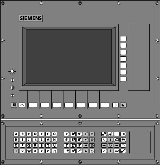
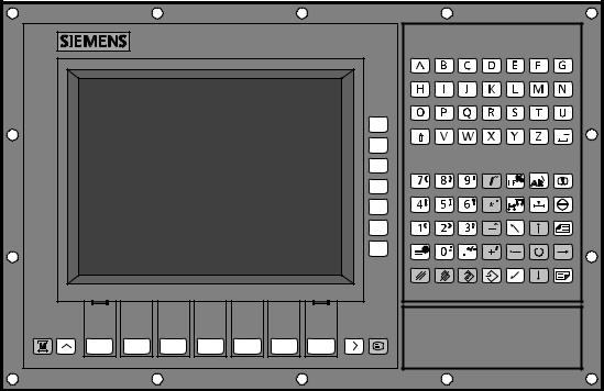
1.1.1Components of SINUMERIK 840C
A detailed list of the SINUMERIK 840C components and their features can be found in the SINUMERIK 840C Catalog and in the Interface Description, Part 2. Some of these components are briefly introduced here to give an overall view of the mechanical design of the control.
The most obvious component of SINUMERIK 840C is the operator panel with machine control panel. Although the operator panel is housed separately from the central unit, it is connected serially to it.
The central unit consists of a single-tier rack which houses the printed circuit boards of the control. In addition to the central unit, SIMATIC expansion units and DMP modules can also be added on to expand the input/output signals.
© Siemens AG 1992 All Rights Reserved |
6FC5197AA00 |
1±3 |
SINUMERIK 840C (PJ)
1 General Overview |
03.95 |
1.1.1 Components of SINUMERIK 840C |
|
GA25.16 |
SINUMERIK slimline operator panel (with
1±4 |
© Siemens AG 1992 All Rights Reserved 6FC5197AA00 |
SINUMERIK 840C (PJ)
12.93 |
1 General Overview |
1.1.1 Components of SINUMERIK 840C
Machine control panel for SINUMERIK slimline operator panel
A |
B |
|
|
|
|
|
|
H |
I |
E |
C |
D |
F |
A:Emergency Stop button
B:Operating modes
C:Spindle control
D:Feed control
E:Direction keys with rapid overlay+customer keys
F:Key operated switch
H:Reset key
I:User
Direction keys for M version |
Direction keys for T version |
E
|
|
|
|
|
|
|
|
|
|
|
|
|
|
|
|
|
|
|
|
|
|
|
|
|
|
|
|
|
|
|
|
|
|
|
|
|
|
|
|
|
|
|
|
|
|
|
|
|
|
|
|
|
|
|
|
|
|
|
|
|
|
|
|
|
|
|
|
|
|
|
|
|
|
|
|
|
|
|
|
|
|
|
|
|
|
|
|
|
|
|
|
|
|
|
|
|
|
|
|
|
|
|
|
|
|
|
|
|
|
|
|
|
|
|
|
|
|
|
|
|
|
|
|
|
© Siemens AG 1992 All Rights Reserved 6FC5197AA00 |
1±5 |
|||||||||||||||||||||||
SINUMERIK 840C (PJ)
1 General Overview |
12.93 |
1.1.1 Components of SINUMERIK 840C
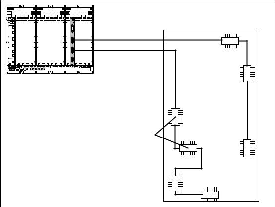
Coupling distributed machine peripherals
|
Line 1 |
|
Line 2 |
|
Central controller |
|
Machine |
|
DMP modules |
* |
Possible only when using the IF-DMP |
1.1.2NCK area
The NCK area essentially comprises:
·Part program memory
·Communications processors (CP)
·Parameters for the control
·UMS
·NCK structure
·Control of axes and spindles
Part program memory
Part programs for workpieces that are currently being machined are stored and managed in the NC area. The part program memory in the NCK area is not battery backed. The part programs can be stored in the data management part of the hard disk (MMC). The data is stored workpiece-oriented.
COM area (CP module)
The SINUMERIK 840C incorporates communication units from MMC and from NCK
·SBC RS232C (V.24)
·MMC interface
·CP module NCK
1±6 |
© Siemens AG 1992 All Rights Reserved 6FC5197AA00 |
SINUMERIK 840C (PJ)
09.95 |
1 General Overview |
1.1.2 NCK area
Parameters for the control
The NC contains different types of control parameters:
·Machine data
All the data fixed by the tool manufacturer which are required for adapting the control to the particular machine tool are stored in the machine data. They include, for example, the position of the reference point, the quantity and names of the axes, characteristics for acceleration and deceleration of the drives and spindle speeds or feed rates. The machine data can be protected by a flexible password.
·Setting data
Setting data are data which can be changed by the machine operator or user. They include, for example, working area limitations.
·PLC machine data
PLC machine data are located in the link RAM NC-PLC area and are used by the manufacturer to define the machine control panel and machine options etc.
The PLC machine data are transferred to the PLC at every cold restart of the NC. All PLC machine data do not become active until cold restart of the PLC.
·Tool offsets
The machine operator stores the geometry and wear data of his tools in the tool offsets.
UMS (user memory submodule)
The operator interface can be configured in order to adapt the functionality of the control to the particular machine and to the requirements of the user. Machine-specific functions (e.g. cycles) or operator interfaces (displays, menus, messages) can be created on the programming workstation ºWS 800Aº. The functions, texts and displays in the machine and parameter areas configured by the machine manufacturer are stored in the UMS. The UMS is a data file on the hard disk on the MMC-CPU of the SINUMERIK 840C. This file is loaded into the NCK when the control powers up and supplements the operator interface of the NCK.
NCK structure
The NCK area is divided into channels, each channel acting like an independent NC control. Each NCK channel has its own block processing and interpolator.
The NCK channels are grouped in operating mode groups. The axes and spindles of the machine are assigned to operating mode groups via machine data. Each NCK channel of an operating mode group can, however, only be controlled by one NCK channel at any one time.
Each axis has a position controller. A position control loop occurs when a drive is connected to the NC via a measuring system. The same applies to spindles with encoders.
In its maximum configuration, SINUMERIK 840C contains 2 operating mode groups (as from SW 4: 6) and 4 NC channels (as from SW 4: 6). It can have a maximum of 15 servo loops (486 CPU) of which a maximum of 6 can be for spindles.
Up to 30 servo loops can be defined with software version 5 and higher (611D).
Example:
The 30 servo loops could be divided into:
·30 axes or 24 axes plus 6 spindles
·No fictitious axes can be defined in addition to the 30 axes.
The limitation to max. 15 real axes or spindles (axes/spindles with servo loops) for analog drives still applies.
The number of servo loops is limited to 9 when using the 386 CPU.
© Siemens AG 1992 All Rights Reserved 6FC5197AA00 |
1±7 |
SINUMERIK 840C (PJ)
1 General Overview |
12.93 |
1.1.3 MMC area
1.1.3MMC area
The MMC area is divided into the
·basic system and
·applications.
The basic system comprises the following:
·standard operating system (FlexOS),
·driver,
·data management,
·master control,
·MMC operator communication system,
·basic tools, such as an ASCII and DIN editor,
·display manager,
·communications coordination.
The following MMC areas are implemented in the application area:
·machine,
·parameters,
·programming,
·diagnostics
·services and
·simulation (as from SW 3)
1.1.4 PLC area
The PLC area contains the interface control. Machine-specific signals are evaluated or switched here. Within the PLC, the basic signals are regrouped, arranged according to the type of signal and denoted ºuser interfaceº. A list of all user interface signals required for the PLC user program appears in Section 2. A detailed description of these signals is to be found in the following sections.
Data communication between the NCK and the PLC is via a communications RAM. In the case of SINUMERIK 840C, with the exception of the basic signals, all signals are stored in data blocks (DB).
1±8 |
© Siemens AG 1992 All Rights Reserved 6FC5197AA00 |
SINUMERIK 840C (PJ)
10.94 |
1 General Overview |
1.1.4 PLC area
MMC
Operator panel
Messages
Data transfer hard disk and RS232C (V.24)
NCK |
|
|
|
PLC |
|
|
|
Data management
Traversing
logic
Position
control
Computer
link
Master computer
|
|
|
|
|
|
|
|
|
|
|
|
NC-PLC |
Interface |
|
|
|
|
|
|
|
|
|
|
|
|
|
|
Operating |
|
||||||
Basic signals |
|
FY 0-24 |
|
|
|
|
|||||
|
|
|
|
System |
|
||||||
Diagnostics |
|
DB 1...4 |
|
|
|
|
|||||
|
|
|
|
|
|
|
|
|
|||
Interface NCK channel 1 to 4 |
(up to 6 |
DB 10-13 |
|
|
|
|
|
|
|
|
|
|
|
|
|
|
|
|
|
||||
as from SW 4) |
|
|
|
|
|
|
|
|
|
|
|
Modes, program modification, |
|
(15 as from SW4) |
|
|
|
|
|
|
|
|
|
Ready signals, auxiliary functions |
|
|
|
|
|
User |
|
||||
Axis-specific 611D and GI signals |
DB 29 |
|
|
|
program |
|
|||||
Decoded M signals |
DB 30 |
|
|
|
|
|
|
|
|
||
|
|
|
|
|
|
|
|
||||
Spindle-specific signals |
DB 31 |
|
|
|
|
|
|
|
|
||
Axis-specific signals |
DB 32 |
|
|
|
|
|
|
|
|
||
PLC-NCK data transfer |
DB 36 |
|
|
|
|
|
|
|
|
||
Control of data transfer |
DB 37 |
|
|
|
|
|
|
|
|
||
Operator panel |
DB 40 |
|
|
|
|
|
|
|
|
||
Command channel |
DB 41 |
|
|
|
|
|
|
|
|
||
NCK/PLC communication |
DB 48 |
|
|
|
|
|
|
|
|
||
PLC messages |
DB 58 |
|
|
|
|
|
|
|
|
||
PLC machine data (MD) |
DB 60 |
|
|
|
|
|
|
|
|
||
PLC MD words, function blocks |
DB 61 |
|
|
|
|
|
|
|
|
||
PLC MD words, users |
DB 62 |
|
|
|
|
|
|
|
|
||
PLC MD bits for basic program |
DB 63 |
|
|
|
|
|
|
|
|
||
PLC MD bits, function blocks |
DB 64 |
|
|
|
|
|
|
|
|
||
PLC MD bits, users |
DB 65 |
|
|
|
|
|
|
|
|
||
DB installed for users, words |
DB 68 |
|
|
|
|
|
|
|
|
||
DB installed for users, bits |
DB 71 |
|
|
|
|
|
|
|
|
||
Computer link |
DB 101, 102 |
|
|
|
|
|
|
|
|
||
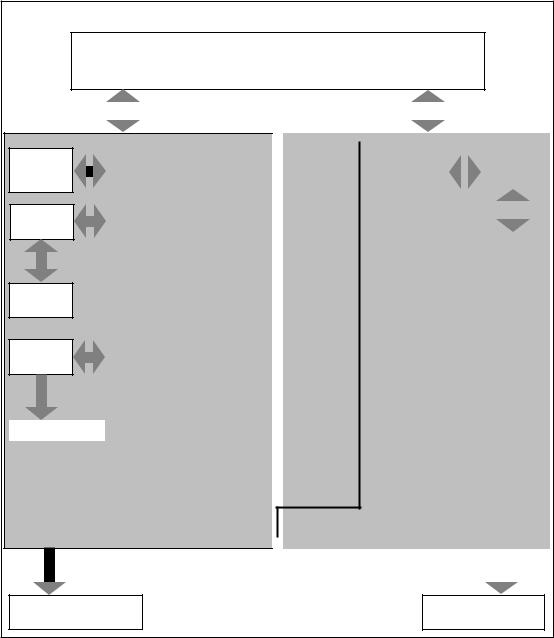
Internal interface |
User interface |
|
|
|
|
|
|
|
|
||
|
|
|
|
|
|
|
|
|
|
|
|
|
|
|
|
|
|
|
|
|
|
|
|
Set and actual values Axes and spindles
Input and output Machine control
Overview of NCK-PLC
NCK PLC data transfer is executed by the PLC operating system (BESY).
© Siemens AG 1992 All Rights Reserved 6FC5197AA00 |
1±9 |
SINUMERIK 840C (PJ)
1 General Overview |
06.93 |
1.1.5 PLC-machine interface
1.1.5PLC-machine
Please refer to the Installation Lists for the assignment of inputs and |
outputs via input and output modules, DMP modules and the machine |
control panel, and the setting of addresses. A description of the |
hardware is contained in the Interface Description, Part 2. |
Input/output overview:
Inputs
Bit No.
Byte No. |
7 |
|
|
|
6 |
|
|
5 |
|
|
4 |
|
|
3 |
|
|
2 |
|
|
1 |
|
|
0 |
|
|
|
|
|
|
|
|
|
|
|
|
|
|
|
|
|
|
|
|
|
|
|
|
0
Physical interface with process image
(input modules, DMP modules, machine control panel)
127
128
Physical interface without process image (input modules, DMP modules)
255
Outputs
Bit No.
Byte No. |
7 |
|
|
|
6 |
|
|
5 |
|
|
4 |
|
|
3 |
|
|
2 |
|
|
1 |
|
|
0 |
|
|
|
|
|
|
|
|
|
|
|
|
|
|
|
|
|
|
|
|
|
|
|
|
0
Physical interface with process image
(output modules, DMP modules, machine control panel)
127
128
Physical interface without process image (output modules, DMP modules)
255
1±10 |
© Siemens AG 1992 All Rights Reserved 6FC5197AA00 |
SINUMERIK 840C (PJ)

12.93 |
1 General Overview |
1.2 PLC program
1.2PLC program
The following subsections provide some information on:
·the structure of the PLC program
·the tasks of the PLC program
·the distribution of tasks between the PLC operating system and the PLC user program
·the fundamental mechanisms of signal and data
The ºPLC 135 WB/WB2/WB Planning Guide SINUMERIK 840C/880º
provides a detailed introduction to programming the PLC
1.2.1Tasks of the PLC program
The SINUMERIK 840C can control a variety of machines. Controlling the drives is among other things one of the classic tasks of the NC which is carried out in the NCK area.
In addition to the machine signals which are required for controlling the drives, there are other signals, different from machine to machine, which cannot be processed with the usual NC functionality. The control is adapted to the signal range of the machine by equipping the PLC area with I/O submodules for creating and switching machine-specific signals.
The PLC user program must establish the connection between the machine-specific signals and the NC functions. This means that the PLC user program creates the signals required by the NC from the machine-specific signals and vice versa i.e. it creates the signals required by the machine from the control signals.
In addition, the PLC user program should use the special features of a machine which are not included in the NC functions. The PLC user program must therefore implement these potential machine functions, activate them when required and monitor them.
Examples of PLC program tasks:
·implementation of monitoring facilities
·activation of machine-specific reactions in the event of errors
·controlling auxiliary axes
·tool magazine management
·execution of auxiliary functions
1.2.2Structure of the PLC program
The PLC program consists of the PLC operating system (BESY) and the PLC user program. The user program is created by the machine manufacturer.
© Siemens AG 1992 All Rights Reserved 6FC5197AA00 |
1±11 |
SINUMERIK 840C (PJ)
1 General Overview |
12.93 |
1.2.2 Structure of the PLC program
1.2.2.1 PLC operating system
The PLC operating system organizes the exchange of signals and data between the PLC user program and the NCK. The individual tasks are as follows:
·Organization of system start
·Preparation of basic signals (flag "0", "1")
·Signal exchange with inputs/outputs
·Exchange of basic signals for channels, axes, spindles
·M decoding
·Data transfer NCK PLC
·Control of data transfer via the PLC
·Acquisition of operator panel signals
·Saving or loading of FW 200/224 ... 254 during time or alarm processing (depending on machine data)
Organization of system start
The PLC operating system can be customized to the user-specific channel, spindle and axis structures of the control via the PLC machine data (see Installation Guide). At cold restart, the PLC operating system checks the machine data and is configured accordingly. In the event of contradictory or incorrect PLC machine data, the PLC operating system branches into the STOP state.
The OB 20 of the PLC user program is called up at system start and processes any commands inserted by the user. The user thus has the possibility to insert a number of functions in the system start. System start is completed when OB 1 is called up the first time. When the OB 1 has been processed completely, the PLC is operating cyclically.
Calling up the user program
The PLC operating system calls up organization blocks. These organization blocks represent the upper level of the PLC user program. These are especially organization blocks for:
·cyclical processing (OB 1)
·interrupt-controlled processing (OB 2)
·alarm-controlled processing (OB 3)
·aperiodic processing (OB 4)
·time-controlled periodic processing (OB 5 - OB 7)
The machine manufacturer can structure his PLC program according to these criteria by calling up program blocks (PB) from the relevant organization blocks (OB).
1±12 |
© Siemens AG 1992 All Rights Reserved 6FC5197AA00 |
SINUMERIK 840C (PJ)
06.93 |
1 General Overview |
1.2.2 Structure of the PLC program
Preparation of basic signals in the flag area
The flag bytes (FY) contain the basic signals for the PLC program. These include (for example) ready signals, basic setting signals, interrupt signals and alarm signals. The PLC operating system provides information on the system state for the PLC user program via the basic signals.
The flag area contains the flag bytes FY 0 to FY 255. The basic signals are located in FY 0 to FY 24. The area FY 25 to FY 255 can be used freely by the user.
Important:
The flag area FY 200 - 223 is also partly used by SIMATIC© function blocks.
Data formats:
All word-oriented interface signals are output and input as fixed-point numbers. Specific reference is made to exceptions.
1.2.2.2 Difference between dynamic and static signals
There are static and dynamic signals.
Static signals are only set or reset by the communicating partners (PLC user program or NC). Static signals retain their value through several PLC cycles, as long as they are not changed by one of the communicating partners.
Dynamic signals on the other hand are reset by the PLC operating system after one PLC cycle. Dynamic signals only occur in the direction going towards the PLC i.e. from the NC or operator panel.
Some dynamic signals are also present in the form of static signals, e.g. M functions.
1.2.3Reaction to interrupt and alarm signals
There are interrupts which are triggered by machine signals (hardware interrupts) and program interrupts which are triggered by the PLC operating system due to edge changes of alarm signals.
Hardware interrupts
Hardware interrupts can only be processed in a particular PLC operating mode, the special mode. The PLC operating system makes an image of the signals which trigger interrupts in the flag area and this image makes it possible to read off which signal has triggered the interrupt. The user interface OB2 is then called up.
The signals which trigger hardware interrupts can be masked. It can be determined which edge of a signal triggers the interrupt via machine data.
Program interrupts due to edge changes of alarm signals
The user can declare certain input bytes as alarm bytes via machine data. The signals stored there trigger program interrupts.
In contrast to hardware interrupts, signals do not trigger program interrupts directly. The PLC operating system updates the list of the ingoing alarm signals in the alarm bytes periodically (approx. every 10ms). If it detects that an edge change has taken place in an alarm byte, OB 3 is activated.
END OF SECTION
© Siemens AG 1992 All Rights Reserved 6FC5197AA00 |
1±13 |
SINUMERIK 840C (PJ)
12.93 |
2 Assigned Areas |
2.1 Flags, data formats
2 Assigned Areas
2.1Flags, data formats
FY |
0 |
Basic signals |
|
|
. |
|
|
|
24 |
|
|
|
|
|
|
|
25 |
e.g. auxiliary flags or for |
|
|
. |
dynamic assignment by |
|
|
. |
interface signals |
|
|
. |
e.g. interface |
channel 1 |
|
. |
||
|
|
channel 2 |
|
|
. |
|
|
|
|
etc. |
|
|
. |
|
|
|
|
|
|
|
. |
Available to the user |
|
|
. |
||
|
|
|
|
|
. |
|
|
|
. |
|
|
|
. |
|
|
|
. |
|
|
|
. |
|
|
|
199 |
|
|
|
|
|
|
|
200 |
Reserved for function |
|
|
. |
blocks (see note) |
|
|
224 |
|
|
|
|
|
|
|
. |
Saved area on changing plane |
|
|
. |
and restarting |
|
|
. |
|
|
|
|
|
|
FY |
255 |
|
|
|
|
|
|
Notes:
1.For the purposes of simple programming, the interface signals from data blocks can be copied into the flag area FY 25 - FY 199 using function macros FB 70 and FB 71.
Function macros are function blocks that are programmed in assembler and integrated in the PLC operating system.
2.The flag area FY 200/224 - 255 (depending on machine data) is saved by the system program when the machining plane is changed and also in the event of a restart. The flag area is uploaded at the end of the relevant program.
This flag area can also be utilized by the user for intermediate results.
The flag area FY 200 - FY 255 is partly used by function blocks (see FB Package Description). If the user does not utilize these function blocks, these flags can be used in the same way as the area FY 25 - FY 199.
Important:
The flag area FY 200 - 255 is also partly used by SIMATIC function blocks.
Data formats:
All word-oriented interface signals are output and input as fixed-point numbers. Specific reference is made to exceptions.
© Siemens AG 1992 All Rights Reserved 6FC5197AA00 |
2±1 |
SINUMERIK 840C (PJ)
 Loading...