


SINUMERIK 840C Software Version 1 to 6
Planning Guide |
09.2001 Edition |
Interface Description
Part 2: Connection Conditions
Manufacturer Documentation
SINUMERIK 840C
Software Version 1, 2, 3, 4, 5 and 6
Interface Description
Part 2: Connection Conditions
Planning Guide
Applies to: |
|
Control |
Software Version |
SINUMERIK 840C/CE |
|
(Standard/Export Version) |
1, 2, 3, 4, 5 and 6 |
09.2001 Edition

SINUMERIK® documentation
Printing history
Brief details of this edition and previous editions are listed below.
The status of each edition is shown by the code in the ”Remarks” column.
Status code in ”Remarks” column:
A. . . New documentation.
B. . . Unrevised reprint with new Order No.
C. . . Revised edition with new status.
If factual changes have been made on the page since the last edition, this is indicated by a new edition coding in the header on that page.
Edition |
Order No. |
Remarks |
11.92 |
6FC5 197-0AA10-1BP0 |
A |
06.93 |
6FC5 197-2AA10-0BP0 |
C |
12.93 |
6FC5 197-3AA10-0BP0 |
C |
06.94 |
6FC5 197-3AA10-0BP1 |
C |
03.95 |
6FC5 197-4AA10-0BP0 |
C |
02.96 |
6FC5 197-5AA10-0BP0 |
C |
01.97 |
6FC5 197-5AA10-0BP2 |
C |
03.98 |
6FC5 197-6AA10-0BP0 |
C |
01.99 |
6FC5 197-6AA10-0BP1 |
C |
07.99 |
6FC5 197-6AA10-0BP2 |
C |
09.01 |
6FC5 197-6AA10-0BP3 |
C |
This manual is included in the documentation on CD-ROM (DOCONCD) |
|
|
Edition |
Order No. |
Remarks |
10.01 |
6FC5198-6CA00-0BG2 |
C |
Trademarks
SIMATIC®, SIMATIC HMI®, SIMATIC NET®, SIROTEC®, SINUMERIK® and SIMODRIVE® are trademarks of Siemens AG. All other product and system names are registered trademarks of their respective companies and must be treated accordingly.
You will find further information in the Internet under: http://www.ad.siemens.de/sinumerik
This publication was produced on the Siemens 5800 Office System .
The reproduction, transmission or use of this document or its contents is not permitted without express written authority. Offenders will be liable for damages. All rights, including rights
created by patent grant or registration of a utility model or design, are reserved.
© Siemens AG 1992-2001
All Rights Reserved
Other functions not described in this documentation might be executable in the control. This does not, however, represent an obligation to supply such functions with a new control or when servicing.
We have checked that the contents of this publication agree with the hardware and software described herein. The information given in this publication is reviewed at regular intervals and any corrections that might be necessary are made in the subsequent printings. Suggestions for improvement are welcome at all times.
Subject to change without prior notice.
Siemens Aktiengesellschaft
Order No. 6FC5197-6AA10-0BP3
Printed in the Federal Republic of Germany
Preliminary
Instructions to the reader
The documentation is intended for manufacturers of machine tools using SINUMERIK 840C. It describes the installation arrangements and wiring between the control and the machine, as well as the signals between the PLC and the machine.
The SINUMERIK documentation comprises four parts:
•General documentation
•User documentation
•Manufacturer documentation and
•Service documentation
The Manufacturer Documentation for the SINUMERIK 840C control is divided into the following sections:
•Planning Guides Interface Part 1: Signals
Interface Part 2: Connection Conditions
•Planning Guide PLC 135 WB/WB2/WD
•Function Macros
•Function Block Packages Package 0 : Basic Functions Package 1 : Tool Management Package 4/5: Computer Link Package 7 : Code Carriers
Package 8 : PLC Controlled Data Input, Output
In addition, there are SINUMERIK publications applying to all SINUMERIK controls (e.g. Universal Interface, Measuring Cycles, CL800 Cycle Language).
Please contact your Siemens regional office for further details.
Technical
Having switched the control off, you must wait at least 5 seconds before switching it on again!
•When signal charts are shown, thick lines represent interface signals and thin lines mean symbolic signal parts or internal messages.
•Signals marked with an * in front of the signal name are so-called inverse signals, i.e. they are not effective at 1 signal but at 0 signal (e.g. *TEMPERATURE ERROR).
In the following Sections you will come across order numbers with a for inserting a number if several versions of a component are available. The complete order number is listed in Section 2, Subsection Hardware overview with order numbers
This documentation is valid for software versions 1, 2, 3, 4, 5 and 6!
Safety guidelines
WARNING
When electrical devices are in operation, certain parts of them are inevitably subjected to hazardous voltages.
Improper interference with the device/system or failure to observe the warning advice can result in serious physical injury or material damage. Only appropriately trained personnel familiar with the assembly, installation, starting up or operation of the product are permitted to interfere with this device/system
Qualified personnel
WARNING
As far as the safety advice (contained in the documentation or as a sticker on the product) is concerned, ”qualified personnel” refers to persons who, for instance:
•have received training or instruction and authorization to energize and deenergize, earth and tag electric circuits and devices according to established safety practices.
•have received training or instruction according to established safety practices in the care, use and repair of appropriate safety equipment.
•have received training or instruction in working with electrostatically sensitive components or modules.
•have been instructed as operators to work with automation technology equipment and are familiar with the contents in the Operator's and/or Programming Guide referring to operation
When planning, installing, starting up, operating and repairing the control, the personnel concerned must be familiar with the documentation relevant to their jobs.
Notes on danger
The following notes are provided for your personal safety and to protect the product described here or connected devices and machines against damage.
Safety advice and warnings intended to avert danger to human life and health and to avoid material damage are highlighted in the Manual by the terms defined here. The terms have the following meanings in the context of this Manual and the remarks on the product itself:
DANGER
As far as this Manual and the warning advice on the products themselves are concerned, ”danger” refers to instances where death, serious physical injury or considerable material damage will result if proper precautions are not taken.
WARNING
As far as this Manual and the warning advice on the products themselves are concerned, ”warning” refers to instances where death, serious physical injury or considerable material damage can result if proper precautions are not taken.
CAUTION
As far as this Manual and the warning advice on the products themselves are concerned, ”caution” refers to instances where slight physical injury or material damage can result if proper precautions are not taken.
CAUTION
This warning notice (without warning triangle) means that a material damage can result if the appropriate precautions are not taken.
NOTICE
This warning notice means that an undesired event or an undesired state can result if the appropriate notices are not observed.
”Note” refers to important items of information about the product or the
part of the Manual to which particular attention must be paid.
Intended use
•The device/system and system components must be used only for the applications envisaged in the Catalog and Reference Manual and only in conjunction with such nonSiemens devices and components as have been recommended and approved by Siemens.
•The product described in the Manual has been developed, manufactured, tested and documented in compliance with the relevant safety standards. Provided that the handling instructions and safety guidelines described for planning, assembling, proper operation and maintenance are observed, the product will not normally be a source of danger as regards material damage or physical injury.
Active and passive faults in automation equipment
•Depending on the particular task for which the electronic automation equipment is used, both active and passive faults can represent dangerous faults. In the case of a drive control, for example, active faults are generally dangerous because they lead to unauthorized startup of the drive. On the other hand, a passive fault can result in a dangerous operating state not being reported to the operator.
•This differentiation between possible faults and their task-related classification as dangerous and non-dangerous faults is important for all the safety considerations in respect of the product supplied.
WARNING
Wherever a fault in the automation equipment can cause serious material damage or even physical injury, in other words wherever dangerous faults can occur, additional external precautions must be taken or devices provided which will ensure or enforce safe operating conditions even in the event of a fault (e.g. by means of independent limit switches, mechanical interlocks etc.).
Notes on product planning
As the product is generally part of larger systems or plants, these notes are intended as a guideline for safe integration of the product in its environment.
Note the following in
Even when a maximum of safety has been designed in an item of automation equipment, e.g. by means of a multichannel configuration, the instructions contained in the Manual must be observed exactly because incorrect handling can render ineffective the preventive measures incorporated to protect against dangerous faults or create new sources of danger.
Additional notes
If measuring or testing work is required on an active piece of equipment, the stipulations and implementation instructions of the VBG 4.0 accident prevention regulation, in particular § 8 ”Permissible departures when working on active parts”, must be observed. Suitable electrical tools must be used.
WARNING
•Repairs to equipment supplied by us must be made only by the
Siemens customer service or by repair services authorized by Siemens. Use only parts contained in the Spare Parts List when renewing parts or components. Unauthorized opening and improper repairs can lead to fatal or serious physical injury and considerable material damage.
•Always pull out the mains connector or open the disconnecting switch before opening the device. Check that the device is not connected to the power supply and ensure that it cannot be switched on.
•Use only the specified types when renewing fuses.
•Do not throw batteries into fires and do not solder on the cell casing owing to the risk of explosion (max. temperature 100°C). Do not open and do not recharge lithium batteries or batteries containing mercury. Use only the same types when replacing.
•All types of batteries must be disposed of as special waste.
•When using monitors:
Improper intervention, in particular changes to the high voltage or installation of a different type of picture tube, can lead to intensified X-rays. Equipment modified in this way no longer complies with the approval and must not be used.
•Dismounted backlight tubes are to be disposed of according to national regulations which also apply to fluorescent tubes.
In the following Sections you will come across order numbers with a for inserting a number if several versions of a component are available. The complete order number is listed in Section 2.2.
System Configuration |
1 |
|
|
|
|
Connections |
2 |
|
|
|
|
Connection Conditions |
3 |
|
|
|
|
Distributed Machine Peripherals (DMP) |
4 |
|
|
|
|
External Devices and Accessories |
5 |
|
|
|
|
Cables and Connectors |
6 |
|
|
|
|
Terms and Abbreviations |
7 |
|
|
|
|
EC Declaration of Conformity |
A |
|
|
|
|
Contents
Page
1 |
System Configuration . . . . . . . . . . . . . . . . . . . . . . . . . . . . . . . . . . . |
1–1 |
1.1SINUMERIK 840C system configuration with
14” color screen . . . . . . . . . . . . . . . . . . . . . . . . . . . . . . . . . . . . . . . |
1–1 |
1.2SINUMERIK 840C system configuration
|
with 9.5”/10” color/monochrome slimline operator panel . . . . . . . . . . . . |
1–2 |
1.3 |
Connection diagram for SINUMERIK 840C with 14” color screen . . . . . |
1–3 |
1.4Connection diagram for SINUMERIK 840C with 14” color screen
and pushbutton module . . . . . . . . . . . . . . . . . . . . . . . . . . . . . . . . . . . |
1–4 |
1.5Connection diagram for SINUMERIK 840C with slimline operator panel
(version from 02.95) . . . . . . . . . . . . . . . . . . . . . . . . . . . . . . . . . . . . . |
1–5 |
1.6Connection diagram for SINUMERIK 840C with 9.5” slimline operator
|
panel and pushbutton module . . . . . . . . . . . . . . . . . . . . . . . . . . . . . . |
1–6 |
1.7 |
Central controller interfaces . . . . . . . . . . . . . . . . . . . . . . . . . . . . . . . . |
1–7 |
1.8 |
SINUMERIK 840C peripherals . . . . . . . . . . . . . . . . . . . . . . . . . . . . . . |
1–8 |
2 |
Connections . . . . . . . . . . . . . . . . . . . . . . . . . . . . . . . . . . . . . . . . . . |
2–1 |
2.1 |
Hardware overview with order numbers . . . . . . . . . . . . . . . . . . . . . |
2–1 |
2.2 |
Operator unit components 6FC5 103-0AB 1-0AA . . . . . . . . . . . . |
2–12 |
2.2.1 |
14” color screen . . . . . . . . . . . . . . . . . . . . . . . . . . . . . . . . . . . . . . . |
2–12 |
2.2.1.1 |
Configuration . . . . . . . . . . . . . . . . . . . . . . . . . . . . . . . . . . . . . . . . . . |
2–12 |
2.2.1.2 |
Location of interfaces and operator control and display elements . . . . . |
2–13 |
2.2.219" operator panel with 10.4" display
|
(replacement part for operator panel with 14" screen) . . . . . . . . . . |
2–15 |
2.2.2.1 |
Location of interfaces, operator control and display elements . . . . . . . . |
2–16 |
2.2.3 |
NC keyboard 6FC5 103-0AC -0AA . . . . . . . . . . . . . . . . . . . . . . |
2–22 |
2.2.3.1 |
Structure . . . . . . . . . . . . . . . . . . . . . . . . . . . . . . . . . . . . . . . . . . . . . |
2–22 |
2.2.3.2 |
Location of interfaces and operator control and display elements . . . . . |
2–23 |
2.2.4 |
Slimline operator panel . . . . . . . . . . . . . . . . . . . . . . . . . . . . . . . . . |
2–24 |
2.2.4.1 |
10” color/monochrome display 6FC5 103-0AB -0AA0 . . . . . . . . . . . |
2–24 |
2.2.4.1.1 |
Configuration . . . . . . . . . . . . . . . . . . . . . . . . . . . . . . . . . . . . . . . . . . |
2–24 |
2.2.4.1.2 |
Location of interfaces and operator control and display elements . . . . . |
2–26 |
2.2.4.1.3 |
Replacing the backlight . . . . . . . . . . . . . . . . . . . . . . . . . . . . . . . . . . . |
2–30 |
2.2.4.2 |
9.5" color/monochrome display 6FC5 103-0AB - AA . . . . . . . . . |
2–33 |
2.2.4.2.1 |
Configuration . . . . . . . . . . . . . . . . . . . . . . . . . . . . . . . . . . . . . . . . . . |
2–33 |
2.2.4.2.2 |
Position of the interfaces, operator control and display elements . . . . . . |
2–35 |
2.2.4.2.3 |
Adjustment with test pattern . . . . . . . . . . . . . . . . . . . . . . . . . . . . . . . |
2–41 |
2.2.4.2.4 |
Replacing the display . . . . . . . . . . . . . . . . . . . . . . . . . . . . . . . . . . . . |
2–44 |
2.2.4.2.5 |
Replacing the backlight . . . . . . . . . . . . . . . . . . . . . . . . . . . . . . . . . . . |
2–47 |
2.2.4.3 |
10.4" color display (as from SW 6) 6FC5 103-0AB 3- AA3 . . . . . . . . |
2–48 |
2.2.4.3.1 |
Configuration . . . . . . . . . . . . . . . . . . . . . . . . . . . . . . . . . . . . . . . . . . |
2–48 |
2.2.4.3.2 |
Location of interfaces, operator controls and display elements . . . . . . . |
2–49 |
2.2.4.3.3 |
Settings/adjustments . . . . . . . . . . . . . . . . . . . . . . . . . . . . . . . . . . . . . |
2–53 |
2.2.4.3.4 |
Replacing the display . . . . . . . . . . . . . . . . . . . . . . . . . . . . . . . . . . . . |
2–58 |
2.2.4.3.5 |
Backlight für 10.4" color display 6FC5147-0AA00-0AA1 . . . . . . . . . . . . |
2–60 |
2.2.5 |
Machine control panel . . . . . . . . . . . . . . . . . . . . . . . . . . . . . . . . . . |
2–62 |
2.2.5.1 |
Configuration . . . . . . . . . . . . . . . . . . . . . . . . . . . . . . . . . . . . . . . . . . |
2–62 |
2.2.5.2 |
Operator control elements of the machine control panel . . . . . . . . . . . . |
2–63 |
2.2.5.3 |
Location of the interfaces and the operator control and display elements |
2–70 |
2.2.6 |
Keyboard interface . . . . . . . . . . . . . . . . . . . . . . . . . . . . . . . . . . . . . |
2–71 |
2.2.6.1 |
Configuration 230 V AC (old) . . . . . . . . . . . . . . . . . . . . . . . . . . . . . . . |
2–71 |
2.2.6.2Configuration 230 V AC (new) 6FC5 103-0AE01-0AA1
|
24 V DC (new) 6FC5 103-0AE01-1AA1 . . . . . . . . . . . . . . . . . . . . . . . . |
2–75 |
2.2.6.3 |
Description of interfaces X211 and X221 . . . . . . . . . . . . . . . . . . . . . . . |
2–79 |
2.2.7 |
Cable sets 1, 2 and 3 . . . . . . . . . . . . . . . . . . . . . . . . . . . . . . . . . . . |
2–81 |
2.2.8 |
Configuring the machine control panel . . . . . . . . . . . . . . . . . . . . . . . . |
2–82 |
2.2.8.1 |
Processing of machine control panel signals . . . . . . . . . . . . . . . . . . . . |
2–83 |
2.2.8.2 |
Input/output assignment of machine control panel . . . . . . . . . . . . . . . . |
2–85 |
2.2.9 |
The pushbutton module 6FX2 006-0AB00 . . . . . . . . . . . . . . . . . . . . |
2–97 |
2.2.9.1 |
Configuration and functionality . . . . . . . . . . . . . . . . . . . . . . . . . . . . . . |
2–97 |
2.2.9.2 |
Position of the interfaces . . . . . . . . . . . . . . . . . . . . . . . . . . . . . . . . . . |
2–98 |
2.2.9.3 |
Hardware interface . . . . . . . . . . . . . . . . . . . . . . . . . . . . . . . . . . . . . . |
2–99 |
2.2.10 |
Voltage converter module UTS 840C . . . . . . . . . . . . . . . . . . . . . . . |
2–104 |
2.2.10.1 |
Connection overview . . . . . . . . . . . . . . . . . . . . . . . . . . . . . . . . . . . . . |
2–104 |
2.2.10.2 |
Hardware interface . . . . . . . . . . . . . . . . . . . . . . . . . . . . . . . . . . . . . . |
2–105 |
2.2.10.3 |
Software interface . . . . . . . . . . . . . . . . . . . . . . . . . . . . . . . . . . . . . . . |
2–108 |
2.2.11 |
Interface changeover switch . . . . . . . . . . . . . . . . . . . . . . . . . . . . . |
2–111 |
2.2.11.1 |
Interface changeover switch, old version . . . . . . . . . . . . . . . . . . . . . . . |
2–111 |
2.2.11.2 |
Interface changeover switch, new version . . . . . . . . . . . . . . . . . . . . . . |
2–114 |
2.2.11.3Connection of one operator panel of one color monitor to several
|
NC controls . . . . . . . . . . . . . . . . . . . . . . . . . . . . . . . . . . . . . . . . . . . |
2–117 |
2.2.11.4 |
Connection of several operator panels/color monitors to an NC control |
. 2–118 |
2.2.12 |
Floppy drive FD-E2 . . . . . . . . . . . . . . . . . . . . . . . . . . . . . . . . . . . . . |
2–120 |
2.3 |
Central controller . . . . . . . . . . . . . . . . . . . . . . . . . . . . . . . . . . . . . . |
2–122 |
2.3.1 |
Configuration . . . . . . . . . . . . . . . . . . . . . . . . . . . . . . . . . . . . . . . . . . |
2–122 |
2.3.1.1Fan unit 6FC5 147-0AA07-0AA0
|
Amplified fan unit 6FC5 147-0AA07-0AA1 . . . . . . . . . . . . . . . . . . . . . . |
2–125 |
2.3.2 |
Subrack assignment . . . . . . . . . . . . . . . . . . . . . . . . . . . . . . . . . . . . |
2–126 |
2.3.2.1 |
Subrack assignment central controller 1, 12 slots . . . . . . . . . . . . . . . . |
2–126 |
2.3.2.2 |
Subrack assignment central controller 2, 18 slots . . . . . . . . . . . . . . . . |
2–127 |
2.3.2.3 |
Subrack assignment central controller 3, 18 + 3 AT slots . . . . . . . . . . |
2–128 |
2.3.3 |
CPU modules . . . . . . . . . . . . . . . . . . . . . . . . . . . . . . . . . . . . . . . . . |
2–129 |
2.3.3.1 |
NC CPU 386DX 6FC5 110-0BA01-1AA0 . . . . . . . . . . . . . . . . . . . . . . . |
2–129 |
2.3.3.1.1 |
EPROM submodule (SW version 1 only) . . . . . . . . . . . . . . . . . . . . . . . |
2–131 |
2.3.3.2 |
NC CPU 486DX . . . . . . . . . . . . . . . . . . . . . . . . . . . . . . . . . . . . . . . . |
2–132 |
2.3.3.3 |
NC CPU 486 DX VB (from 08.94) 6FC5 110-0BB0 -0AA . . . . . . . . . |
2–134 |
2.3.3.4 |
PLC CPU 135 WB2 . . . . . . . . . . . . . . . . . . . . . . . . . . . . . . . . . . . . . |
2–136 |
2.3.3.4.1 |
EPROM submodule 256 Kbytes . . . . . . . . . . . . . . . . . . . . . . . . . . . . . |
2–138 |
2.3.3.5 |
PLC CPU 135 WD . . . . . . . . . . . . . . . . . . . . . . . . . . . . . . . . . . . . . . |
2–139 |
2.3.3.6 |
MMC CPU 386SX 6FC5 110-0DA0 -0AA0 . . . . . . . . . . . . . . . . . . . . . |
2–142 |
2.3.3.7 |
MMC CPU 486 SX/DX (SW 2 and higher) . . . . . . . . . . . . . . . . . . . . . . |
2–145 |
2.3.4 |
I/O modules . . . . . . . . . . . . . . . . . . . . . . . . . . . . . . . . . . . . . . . . . . |
2–148 |
2.3.4.1ANALOG measuring circuit module without/with EXEs
|
6FC5 111-0BA0 -0AA0 . . . . . . . . . . . . . . . . . . . . . . . . . . . . . . . . . . |
2–148 |
2.3.4.1.1 |
EXE 5/10-fold . . . . . . . . . . . . . . . . . . . . . . . . . . . . . . . . . . . . . . . . . . |
2–154 |
2.3.4.2 |
HMS measuring circuit module . . . . . . . . . . . . . . . . . . . . . . . . . . . . . |
2–155 |
2.3.4.2.1 |
SERVO COMMAND submodule . . . . . . . . . . . . . . . . . . . . . . . . . . . . . |
2–160 |
2.3.4.2.2 |
SIPOS absolute encoder submodule . . . . . . . . . . . . . . . . . . . . . . . . . |
2–161 |
2.3.4.2.3 |
I/V hybrid . . . . . . . . . . . . . . . . . . . . . . . . . . . . . . . . . . . . . . . . . . . . . |
2–162 |
2.3.4.3 |
IN ANALOG I/O module . . . . . . . . . . . . . . . . . . . . . . . . . . . . . . . . . . |
2–163 |
2.3.4.4 |
MIXED I/O module 6FC5 111-0CB02-0AA0 . . . . . . . . . . . . . . . . . . . . . |
2–170 |
2.3.5 |
Interfaces . . . . . . . . . . . . . . . . . . . . . . . . . . . . . . . . . . . . . . . . . . . . |
2–177 |
2.3.5.1 |
PLC interface . . . . . . . . . . . . . . . . . . . . . . . . . . . . . . . . . . . . . . . . . . |
2–177 |
2.3.5.2 |
DMP interface . . . . . . . . . . . . . . . . . . . . . . . . . . . . . . . . . . . . . . . . . |
2–180 |
2.3.5.3 |
EU interface, 16 bit . . . . . . . . . . . . . . . . . . . . . . . . . . . . . . . . . . . . . . |
2–183 |
2.3.5.4 |
PROFIBUS DP interface . . . . . . . . . . . . . . . . . . . . . . . . . . . . . . . . . . |
2–184 |
2.3.5.5 |
Adapter kit for IM308C (as from SW 6) . . . . . . . . . . . . . . . . . . . . . . . . |
2–185 |
2.3.5.6 |
Bus interface SINEC CP 231A . . . . . . . . . . . . . . . . . . . . . . . . . . . . . . |
2–187 |
2.3.5.6.1 |
System software submodule for CP 231 6FC5 154-0AX01-1AE0 |
|
|
System software submodule for CP 315 . . . . . . . . . . . . . . . . . . . . . . . |
2–189 |
2.3.5.7 |
CP 315 – ACTIVE V.24 module . . . . . . . . . . . . . . . . . . . . . . . . . . . . . |
2–190 |
2.3.5.8 |
CP 315/CP 373 – ACTIVE V.24 module with submodule . . . . . . . . . . . |
2–192 |
2.3.5.9 |
SINEC CP 1476 (MAP 3.0) . . . . . . . . . . . . . . . . . . . . . . . . . . . . . . . . |
2–193 |
2.3.5.10 |
MMC interface . . . . . . . . . . . . . . . . . . . . . . . . . . . . . . . . . . . . . . . . . |
2–194 |
2.3.6 |
Monitoring module and power supply . . . . . . . . . . . . . . . . . . . . . . |
2–197 |
2.3.6.1 |
CENTRAL SERVICE BOARD (old CSB) . . . . . . . . . . . . . . . . . . . . . . . |
2–197 |
2.3.6.2 |
CENTRAL SERVICE BOARD (new CSB) . . . . . . . . . . . . . . . . . . . . . . |
2–203 |
2.3.6.3 |
Cable distributor . . . . . . . . . . . . . . . . . . . . . . . . . . . . . . . . . . . . . . . . |
2–207 |
2.3.6.4 |
Power supply of central controller . . . . . . . . . . . . . . . . . . . . . . . . . . . |
2–214 |
2.3.7 |
Blanking plates . . . . . . . . . . . . . . . . . . . . . . . . . . . . . . . . . . . . . . . |
2–215 |
2.3.8 |
AT rack expansion on central controller 3 . . . . . . . . . . . . . . . . . . . |
2–216 |
3 |
Connection Conditions . . . . . . . . . . . . . . . . . . . . . . . . . . . . . . . . . |
3–1 |
3.1 |
Technical data . . . . . . . . . . . . . . . . . . . . . . . . . . . . . . . . . . . . . . . . |
3–1 |
3.1.1 |
Climatic environmental conditions . . . . . . . . . . . . . . . . . . . . . . . . . |
3–1 |
3.1.1.1 |
Installation and operation . . . . . . . . . . . . . . . . . . . . . . . . . . . . . . . . . . |
3–2 |
3.1.1.2 |
Transportation and storage . . . . . . . . . . . . . . . . . . . . . . . . . . . . . . . . |
3–2 |
3.1.2 |
Exposure to contaminants . . . . . . . . . . . . . . . . . . . . . . . . . . . . . . . |
3–4 |
3.1.2.1 |
Hazardous gases . . . . . . . . . . . . . . . . . . . . . . . . . . . . . . . . . . . . . . . |
3–4 |
3.1.2.2 |
Hazardous dust . . . . . . . . . . . . . . . . . . . . . . . . . . . . . . . . . . . . . . . . |
3–5 |
3.1.3 |
Electromagnetic compatibility (EMC) . . . . . . . . . . . . . . . . . . . . . . . |
3–5 |
3.1.3.1 |
Interference suppression . . . . . . . . . . . . . . . . . . . . . . . . . . . . . . . . . . |
3–5 |
3.1.3.2 |
Immunity to noise . . . . . . . . . . . . . . . . . . . . . . . . . . . . . . . . . . . . . . . |
3–5 |
3.1.4 |
Miscellaneous . . . . . . . . . . . . . . . . . . . . . . . . . . . . . . . . . . . . . . . . |
3–6 |
3.1.4.1 |
Colors . . . . . . . . . . . . . . . . . . . . . . . . . . . . . . . . . . . . . . . . . . . . . . . |
3–6 |
3.1.4.2 |
Data protection, stored energy times . . . . . . . . . . . . . . . . . . . . . . . . . |
3–6 |
3.2 |
Technical data of the individual components . . . . . . . . . . . . . . . . . |
3–7 |
3.2.1 |
Mechanical data and temperature ranges of the individual components |
3–7 |
3.2.2 |
Electrical data of the individual components . . . . . . . . . . . . . . . . . |
3–10 |
3.2.2.1 |
Requirements for power supply . . . . . . . . . . . . . . . . . . . . . . . . . . . . . |
3–11 |
3.2.2.2 |
Connected load and power loss calculation . . . . . . . . . . . . . . . . . . . . . |
3–13 |
3.2.3 |
Standards . . . . . . . . . . . . . . . . . . . . . . . . . . . . . . . . . . . . . . . . . . . . |
3–16 |
3.3 |
Mechanical installation . . . . . . . . . . . . . . . . . . . . . . . . . . . . . . . . . . |
3–18 |
3.3.1 |
Operator panel with 14” color screen . . . . . . . . . . . . . . . . . . . . . . . |
3–18 |
3.3.1.1 |
Dimension drawings . . . . . . . . . . . . . . . . . . . . . . . . . . . . . . . . . . . . . |
3–18 |
3.3.1.2 |
Panel cutout . . . . . . . . . . . . . . . . . . . . . . . . . . . . . . . . . . . . . . . . . . . |
3–20 |
3.3.1.3 |
Installation notes . . . . . . . . . . . . . . . . . . . . . . . . . . . . . . . . . . . . . . . . |
3–22 |
3.3.1.4 |
Heat removal . . . . . . . . . . . . . . . . . . . . . . . . . . . . . . . . . . . . . . . . . . |
3–23 |
3.3.219” operator panel with 10.4” display
|
(spare part for operator panel with 14” screen) . . . . . . . . . . . . . . . |
3–25 |
3.3.2.1 |
Dimension drawings . . . . . . . . . . . . . . . . . . . . . . . . . . . . . . . . . . . . . |
3–25 |
3.3.3 |
9.5”,10” and 10.4” color/monochrome slimline operator panel . . . . |
3–28 |
3.3.3.1 |
Dimension drawings . . . . . . . . . . . . . . . . . . . . . . . . . . . . . . . . . . . . . |
3–28 |
3.3.3.2 |
Panel cutout (9.5", 10", 10.4") . . . . . . . . . . . . . . . . . . . . . . . . . . . . . |
3–32 |
3.3.3.3 |
Installation notes . . . . . . . . . . . . . . . . . . . . . . . . . . . . . . . . . . . . . . . . |
3–33 |
3.3.3.4 |
Heat removal . . . . . . . . . . . . . . . . . . . . . . . . . . . . . . . . . . . . . . . . . . |
3–35 |
3.3.4 |
NC keyboard . . . . . . . . . . . . . . . . . . . . . . . . . . . . . . . . . . . . . . . . . |
3–37 |
3.3.4.1 |
Dimension drawings . . . . . . . . . . . . . . . . . . . . . . . . . . . . . . . . . . . . . |
3–37 |
3.3.4.2 |
Panel cutout . . . . . . . . . . . . . . . . . . . . . . . . . . . . . . . . . . . . . . . . . . . |
3–38 |
3.3.5 |
Machine control panel . . . . . . . . . . . . . . . . . . . . . . . . . . . . . . . . . . |
3–39 |
3.3.5.1 |
Dimension drawings . . . . . . . . . . . . . . . . . . . . . . . . . . . . . . . . . . . . . |
3–39 |
3.3.5.2 |
Panel cutout . . . . . . . . . . . . . . . . . . . . . . . . . . . . . . . . . . . . . . . . . . . |
3–40 |
3.3.6 |
Voltage converter module UTS 840C . . . . . . . . . . . . . . . . . . . . . . . |
3–40 |
3.3.7 |
Central controller . . . . . . . . . . . . . . . . . . . . . . . . . . . . . . . . . . . . . . |
3–41 |
3.3.7.1 |
Dimension drawings . . . . . . . . . . . . . . . . . . . . . . . . . . . . . . . . . . . . . |
3–41 |
3.3.7.2 |
Heat removal . . . . . . . . . . . . . . . . . . . . . . . . . . . . . . . . . . . . . . . . . . |
3–47 |
3.3.8 |
Floppy drive FD-E2 . . . . . . . . . . . . . . . . . . . . . . . . . . . . . . . . . . . . . |
3–48 |
3.3.8.1 |
Dimension drawings . . . . . . . . . . . . . . . . . . . . . . . . . . . . . . . . . . . . . |
3–48 |
3.3.8.2 |
Panel cutout . . . . . . . . . . . . . . . . . . . . . . . . . . . . . . . . . . . . . . . . . . . |
3–49 |
3.3.9 |
Cable strain relief and shielding on CPU modules . . . . . . . . . . . . . |
3–50 |
3.4 |
Electrical installation . . . . . . . . . . . . . . . . . . . . . . . . . . . . . . . . . . . |
3–51 |
3.4.1 |
Installation codes of practice . . . . . . . . . . . . . . . . . . . . . . . . . . . . . |
3–51 |
3.4.1.1 |
Installation of equipotential bonding conductors . . . . . . . . . . . . . . . . . . |
3–52 |
3.4.1.2 |
Laying signal and power lines . . . . . . . . . . . . . . . . . . . . . . . . . . . . . . |
3–55 |
3.4.1.3 |
Potential connection with external 24 V power supply . . . . . . . . . . . . . . |
3–56 |
3.4.1.4 |
Potential connection with 230 V AC power supply . . . . . . . . . . . . . . . . |
3–56 |
3.4.2 |
Shock hazard protection . . . . . . . . . . . . . . . . . . . . . . . . . . . . . . . . |
3–56 |
3.5 |
Maintenance and servicing . . . . . . . . . . . . . . . . . . . . . . . . . . . . . . . |
3–56 |
3.5.1 |
Electrostatically sensitive devices (ESD) . . . . . . . . . . . . . . . . . . . . |
3–56 |
3.5.2 |
Handling the modules . . . . . . . . . . . . . . . . . . . . . . . . . . . . . . . . . . |
3–57 |
3.5.3 |
Cleaning . . . . . . . . . . . . . . . . . . . . . . . . . . . . . . . . . . . . . . . . . . . . . |
3–58 |
3.5.4 |
Replacing batteries . . . . . . . . . . . . . . . . . . . . . . . . . . . . . . . . . . . . . |
3–58 |
3.5.5 |
Recommendations for hard disks . . . . . . . . . . . . . . . . . . . . . . . . . . |
3–59 |
3.6 |
Disposing of components . . . . . . . . . . . . . . . . . . . . . . . . . . . . . . . |
3–64 |
4 |
Distributed Machine Peripherals (DMP) . . . . . . . . . . . . . . . . . . . . . |
4–1 |
4.1 |
General . . . . . . . . . . . . . . . . . . . . . . . . . . . . . . . . . . . . . . . . . . . . . . |
4–1 |
4.2 |
Examples of application . . . . . . . . . . . . . . . . . . . . . . . . . . . . . . . . . . |
4–2 |
4.3 |
DMP terminator . . . . . . . . . . . . . . . . . . . . . . . . . . . . . . . . . . . . . . . . |
4–6 |
4.4 |
DMP terminal block and DMP modules . . . . . . . . . . . . . . . . . . . . . . . . |
4–7 |
4.4.1 |
DMP terminal block . . . . . . . . . . . . . . . . . . . . . . . . . . . . . . . . . . . . . |
4–7 |
4.4.2 |
DMP module 16 I/16 O . . . . . . . . . . . . . . . . . . . . . . . . . . . . . . . . . . . |
4–8 |
4.4.3 |
DMP module 32 I . . . . . . . . . . . . . . . . . . . . . . . . . . . . . . . . . . . . . . . |
4–11 |
4.5 |
DMP compact terminal block and DMP compact modules . . . . . . . . . . |
4–13 |
4.5.1 |
DMP compact terminal block . . . . . . . . . . . . . . . . . . . . . . . . . . . . . . . |
4–13 |
4.5.2 |
DMP compact module 8 O . . . . . . . . . . . . . . . . . . . . . . . . . . . . . . . . |
4–15 |
4.5.3 |
DMP compact module 16 O . . . . . . . . . . . . . . . . . . . . . . . . . . . . . . . |
4–17 |
4.5.4 |
DMP compact module 16 I . . . . . . . . . . . . . . . . . . . . . . . . . . . . . . . . |
4–19 |
4.5.5 |
DMP compact module ANALOG OUT . . . . . . . . . . . . . . . . . . . . . . . . |
4–20 |
4.5.6 |
DMP compact module ANALOG IN . . . . . . . . . . . . . . . . . . . . . . . . . . |
4–22 |
4.6DMP terminal block with DMP module 6FC5 111-0CA72-0AA0
|
in IP 65 design . . . . . . . . . . . . . . . . . . . . . . . . . . . . . . . . . . . . . . . . |
4–26 |
4.7 |
Machine control panel as DMP station . . . . . . . . . . . . . . . . . . . . . . . . |
4–31 |
4.8 |
Handheld unit and distribution box . . . . . . . . . . . . . . . . . . . . . . . . . . . |
4–31 |
4.8.1 |
Handheld unit with casing . . . . . . . . . . . . . . . . . . . . . . . . . . . . . . . . . |
4–32 |
4.8.1.1 |
Distribution box for handheld unit . . . . . . . . . . . . . . . . . . . . . . . . . . . . |
4–39 |
4.8.2 |
Handheld unit for mounting without housing . . . . . . . . . . . . . . . . . . . . |
4–41 |
4.8.3 |
A-MPC handheld unit with casing . . . . . . . . . . . . . . . . . . . . . . . . . . . . |
4–43 |
4.8.3.1 |
Distribution box for handheld unit 6FX2 006-1BC0 . . . . . . . . . . . . . . |
4–53 |
4.8.4 |
Earthing concept for distributed machine peripherals . . . . . . . . . . . . . . |
4–55 |
5 |
External Devices and Accessories . . . . . . . . . . . . . . . . . . . . . . . . . |
5–1 |
5.1 |
Devices and accessories . . . . . . . . . . . . . . . . . . . . . . . . . . . . . . . . . |
5–1 |
5.2 |
Electronic handwheels . . . . . . . . . . . . . . . . . . . . . . . . . . . . . . . . . . . |
5–3 |
5.2.1 |
Electronic handwheel, large . . . . . . . . . . . . . . . . . . . . . . . . . . . . . . . . |
5–3 |
5.2.2 |
Electronic handwheel, small . . . . . . . . . . . . . . . . . . . . . . . . . . . . . . . |
5–4 |
5.2.3 |
Electronic handwheel with housing 6FC9 320-5DE00 . . . . . . . . . . . . . . |
5–5 |
5.3 |
3.5” FD-E1 built-in floppy drive . . . . . . . . . . . . . . . . . . . . . . . . . . . . . |
5–6 |
5.4 |
Spring disk coupling with clamp . . . . . . . . . . . . . . . . . . . . . . . . . . . . . |
5–7 |
5.5INDUCTOSYN converter 6FC9 320-3GK
|
INDUCTOSYN pre-amplifier 6FC9 320-4FC . . . . . . . . . . . . . . . . . . . . |
5–8 |
5.5.1 |
Wiring . . . . . . . . . . . . . . . . . . . . . . . . . . . . . . . . . . . . . . . . . . . . . . . |
5–8 |
5.5.2 |
Dimension drawings . . . . . . . . . . . . . . . . . . . . . . . . . . . . . . . . . . . . . |
5–10 |
5.6Terminal strip converter, 37-pin, for input module and mixed
|
input/output module (with LEDs) 6FC9 302-2BD01 . . . . . . . . . . . . . . . . |
5–11 |
5.7 |
400 V AC power supply units . . . . . . . . . . . . . . . . . . . . . . . . . . . . . . . |
5–12 |
5.8 |
Standard PC keyboard (MF-II) . . . . . . . . . . . . . . . . . . . . . . . . . . . . . . |
5–13 |
5.9 |
Streamers . . . . . . . . . . . . . . . . . . . . . . . . . . . . . . . . . . . . . . . . . . . . |
5–15 |
5.9.1 |
VALITEK PST 160 streamer 6FC9 310-1NB00 . . . . . . . . . . . . . . . . . . |
5–15 |
5.9.2 |
VALITEK PST 2-M1200 streamer 6FX2 007-2AA00 . . . . . . . . . . . . . . . |
5–15 |
5.10 |
Encoders . . . . . . . . . . . . . . . . . . . . . . . . . . . . . . . . . . . . . . . . . . . . . |
5–16 |
5.10.1 |
High-resolution rotary encoder for rotary axes . . . . . . . . . . . . . . . . . . . |
5–16 |
5.10.2 |
Incremental rotary encoder and main spindle encoder . . . . . . . . . . . . . |
5–17 |
5.10.3 |
Combined rotary encoder for spindle and C axis 6FC9 320-3KT00 . . . . |
5–18 |
5.10.4 |
SIPOS encoders . . . . . . . . . . . . . . . . . . . . . . . . . . . . . . . . . . . . . . . . |
5–19 |
6 |
Cables and Connectors . . . . . . . . . . . . . . . . . . . . . . . . . . . . . . . . . |
6–1 |
6.1 |
Tabular overview of cables . . . . . . . . . . . . . . . . . . . . . . . . . . . . . . . . |
6–1 |
6.2 |
Tabular overview of connectors . . . . . . . . . . . . . . . . . . . . . . . . . . . . . |
6–5 |
6.3 |
Cable diagrams and connector assignment . . . . . . . . . . . . . . . . . . . . . |
6–6 |
6.4 |
Description of cables and connectors . . . . . . . . . . . . . . . . . . . . . . . . . |
6–39 |
7 |
Terms and Abbreviations . . . . . . . . . . . . . . . . . . . . . . . . . . . . . . . . |
7–1 |
A |
EC Declaration of Conformity . . . . . . . . . . . . . . . . . . . . . . . . . . . . . |
A–1 |
03.95 |
1 System Configuration |
1.1 SINUMERIK 840C system configuration with 14º color screen
1 System Configuration
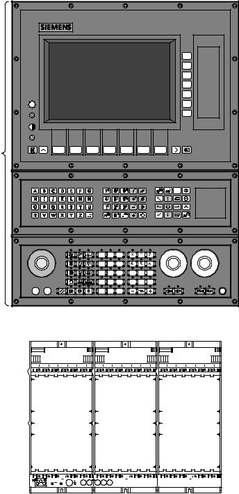
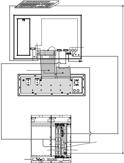
1.1SINUMERIK 840C system configuration with 14º color screen
14º color screen
Operator unit
NC keyboard
Machine control panel with M or T
labelling
Subrack ± central controller, not equipped, with 12 or 18 slots (see left) or 18+3 AT slots (SW 3 and
|
|
|
|
|
|
|
|
|
|
|
|
|
|
|
|
|
|
|
|
|
|
|
|
|
|
|
|
|
|
|
|
|
|
|
|
|
|
|
|
|
|
|
|
|
|
|
|
|
|
|
|
|
|
|
|
|
1±1 |
|
|
|
|
|
|
|
|
|
|
|
|
|
|
|
|
|
|
|
|
|
|
|
|
|
|
|
|
|
|
|
|
|
|
|
|
|
|
|
|
|
|
|
|
|
|
|
|
|
|
|
|
|
|
|
|
|
|
© Siemens AG 1992 All Rights Reserved 6FC5197AA10 |
|||||||||||||||||||||||||||||||||||||||||||||||||||||||||
SINUMERIK 840C (PJ)
1 System Configuration |
07.99 |
1.2 SINUMERIK 840C system configuration with 9.5º/10º/10.4º color/monochrome slimline operator panel
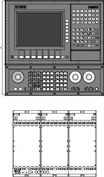
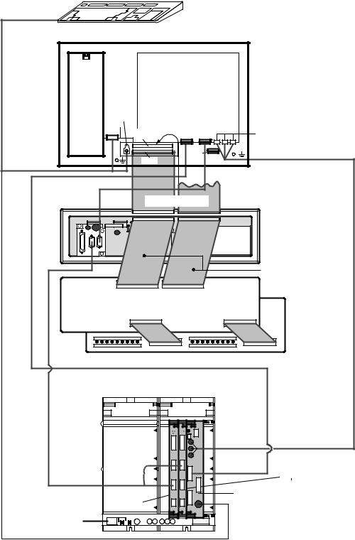
1.2SINUMERIK 840C system configuration
with 9.5º/10º/10.4º color/monochrome slimline operator panel
9.5º/10º/10.4º slimline operator panel, monochrome
or color
Operator unit
Machine control panel, with M or T labelling
Subrack ±
central controller, not equipped,
with 12 or 18 slots (see left) or 18+3 AT slots (SW 3 and
1±2 |
|
|
|
|
|
|
|
|
|
|
|
|
|
|
|
|
|
|
|
|
|
|
|
|
|
|
|
|
|
|
|
|
|
|
|
|
|
|
|
|
|
|
|
|
|
|
|
|
|
|
|
|
|
|
|
|
|
|
|
|
|
|
|
|
|
|
|
|
|
|
|
|
|
|
|
|
|
|
|
|
|
|
|
|
|
|
|
|
|
|
|
|
|
|
|
|
|
|
|
|
|
|
|
|
|
|
|
|
|
|
|
|
|
|
|
|
|
|
|
|
|
|
|
|
|
|
|
|
|
|
|
|
|
|
|
|
|
|
|
|
|
|
|
|
|
|
|
© Siemens AG 1992 All Rights Reserved 6FC5197AA10 |
|||||||||||||||||||||||||
SINUMERIK 840C (PJ)
12.93 |
1 System Configuration |
1.3Connection diagram for SINUMERIK 840C with 14º color screen
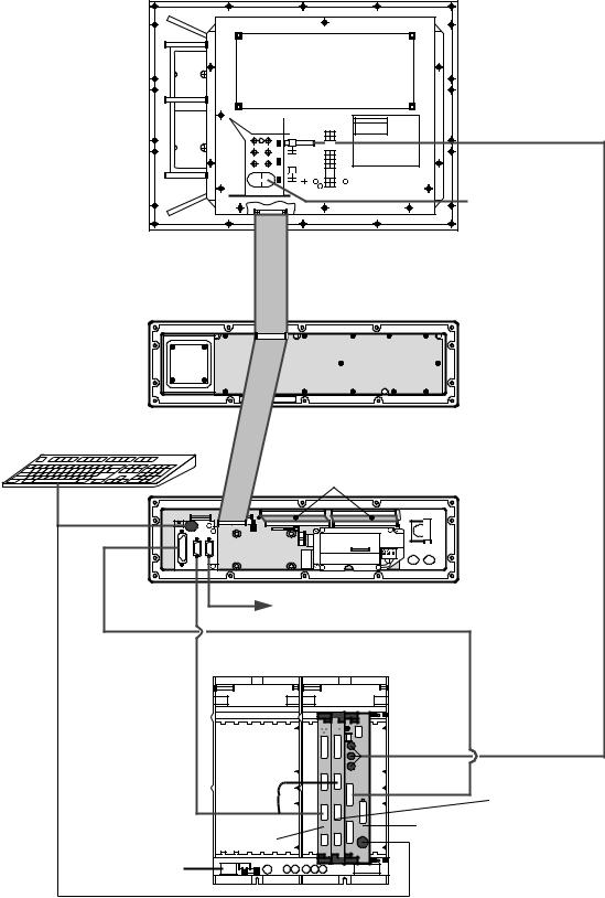
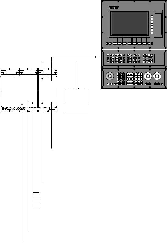
1.3Connection diagram for SINUMERIK 840C with 14º color screen
Display unit
230 V AC |
Cable supplied with
 display unit
NC keyboard
PC standard keyboard
Set of cables 1
Machine control panel with keyboard interface
 230 V AC see Section 4, DMP
6FC9 340-8W |
|
6FC9 344-3S |
|
|
Central |
|
controller |
|
RGB cable |
|
6FC9 344-4N 01 |
|
PLC interface |
|
(PLC 135 WB2 |
|
only) |
PLC CPU |
MMC CPU |
135 WD |
|
230 V AC |
|
© Siemens AG 1992 All Rights Reserved 6FC5197AA10 |
1±3 |
SINUMERIK 840C (PJ)

1 System Configuration |
01.97 |
1.4 Connection diagram for SINUMERIK 840C with 14º color screen and pushbutton module
1.4Connection diagram for SINUMERIK 840C with 14º color screen and pushbutton module
PC standard keyboard |
Display unit |
 230 V AC
Cable supplied with
 display unit
NC keyboard with keyboard interface
Set of cables 1 or
Machine control panel with keyboard interface
Cables: supplied with voltage converter
Voltage converter 6FX2 006-0AA00
|
Pushbutton module |
6FC9 340-8W |
6FX2 006-0AB00 |
6FC9 344-3S |
|
|
Central |
|
controller |
|
RGB cable |
|
6FC9 344-4N 01 |
|
Interface |
|
PLC (PLC 135 |
|
WB2 only) |
PLC CPU |
MMC CPU |
135 WD |
|
230 V AC |
|
1±4 |
© Siemens AG 1992 All Rights Reserved 6FC5197AA10 |
SINUMERIK 840C (PJ)
03.95 |
1 System Configuration |
1.5Connection diagram for SINUMERIK 840C with slimline operator panel (version from 02.95)
1.5Connection diagram for SINUMERIK 840C with slimline operator panel (version from 02.
PC standard keyboard
Slimline operator panel
230 V AC or
24 V DC
X251 |
|
X241 |
X261 |
X111 |
X121 X131 |
X141 |
X331 |
X211, X221, X231 (RGB)
See Section 4, DMP
Set of cables 2 |
|
|
Machine |
|
|
control |
|
|
panel |
|
|
without |
|
|
keyboard |
|
|
interface |
|
RGB cable |
|
|
6FC9 344-4N 01 |
|
|
6FC9 340-8W |
|
|
Central |
|
|
controller |
6FC9 344-3S |
|
Interface |
|
|
|
|
|
PLC (PLC 135 |
|
PLC CPU |
WB2 |
|
MMC CPU |
|
|
135 WD |
|
230 V AC |
|
|
|
|
|
or 24 V DC |
|
|
© Siemens AG 1992 All Rights Reserved 6FC5197AA10 |
1±5 |
SINUMERIK 840C (PJ)
1 System Configuration |
01.97 |
1.6 Connection diagram for SINUMERIK 840C with 9.5º slimline operator panel and pushbutton module
1.6Connection diagram for SINUMERIK 840C with 9.5º slimline operator panel and pushbutton module
PC standard keyboard
Slimline operator
230 V AC or
24 V DC
X251
X241 |
|
X261 |
|
X111 |
X121 X131 |
X211, X221, X231 (RGB) |
X141 |
X331 |
Set of cables 2
|
Machine control |
230 V AC |
panel with |
or |
keyboard interface |
24 V DC |
|
|
Cables: supplied with |
|
voltage converter |
Voltage converter 6FX2 006-0AA00
|
Pushbutton module |
6FC9 340-8W |
6FX2 006-0AB00 |
6FC9 344-3S |
|
|
Central |
|
controller |
|
RGB cable |
|
6FC9 344-4N 01 |
|
Interface |
|
PLC (PLC 135 |
|
WB2 only) |
PLC-CPU |
MMC-CPU |
135 WD |
|
230 V AC |
|
or |
|
24 V DC |
|
1±6 |
© Siemens AG 1992 All Rights Reserved 6FC5197AA10 |
SINUMERIK 840C (PJ)
03.95 |
1 System Configuration |
1.7 Central controller interfaces
1.7Central controller interfaces
PS |
NCK |
PLC |
MMC |
|
|
|
SIMATIC-EU |
 Centronics-S5 (archiving, streamer)
 RS232C (V.24) (operator panel)
 RS232C (V.24)(e.g. floppy drive, programming unit)
 RGB, analog
 FD-E2 diskette drive interface (SW3 and higher)
 Machine control panel
 Pushbutton module
 Distributed machine peripherals (DMP)
 Programming unit
 High-speed PLC inputs
 Handheld unit
Actual values
Handwheels 1 and 2
Measuring pulse input
Network interfaces (e.g. SINEC H1)
 Setpoint values
 NC Ready
 Fan/temperature alarm
 SIMODRIVE
© Siemens AG 1992 All Rights Reserved 6FC5197AA10 |
1±7 |
SINUMERIK 840C (PJ) |
|
1 System Configuration |
01.97 |
1.8 SINUMERIK 840C peripherals
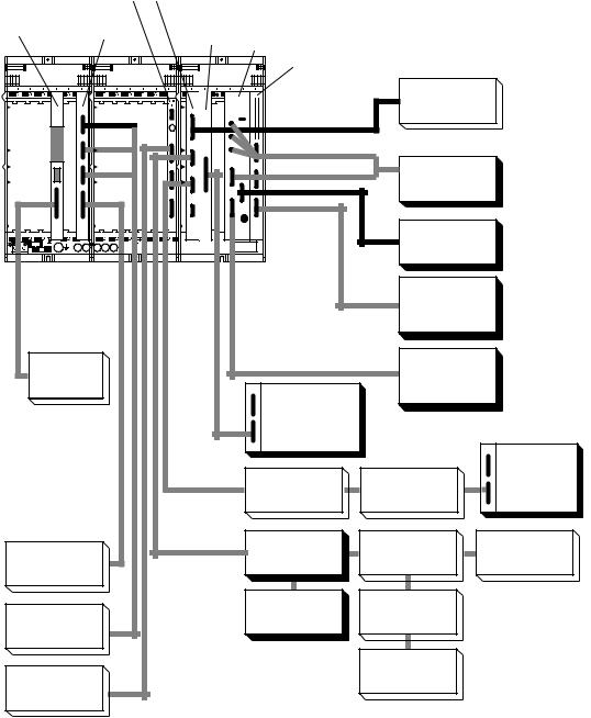
1.8SINUMERIK 840C peripherals
For SINUMERIK 840C systems, the inputs/outputs from/to the machine can be connected either in
·a central configuration via the central controller modules
·a distributed configuration via an RS 485/MPC link or
·a distributed configuration via a 16-bit link.
I/O interfaces: SINUMERIK 840C (maximum configuration) ±
NC-CPU
Measuring
circuit module
CSB
135 WD PLC (slot C1) or
Interface PLC (slot C2)
Interface EU 16 Bit
MMC-CPU
MMC interface (SW3 and higher)
|
|
Programming |
|
|
|
|
unit (S5) |
|
|
|
|
Operator |
|
|
|
|
panel |
|
|
|
|
Streamer |
|
|
Handwheel, |
|
|
|
|
measuring |
|
|
|
|
pulses |
|
|
|
|
|
DMP |
DMP |
|
|
|
station |
station |
|
|
SIMODRIVE |
Keyboard |
Keyboard |
DMP |
|
interface |
interface |
station |
||
drive |
||||
|
|
|
||
Actual value |
|
Voltage |
|
|
|
converter |
|
||
encoder |
|
|
|
|
|
|
Pushbutton |
|
|
SIMODRIVE |
|
module |
|
|
611D |
END OF SECTION |
|
|
|
|
|
|
1±8 |
© Siemens AG 1992 All Rights Reserved 6FC5197AA10 |
SINUMERIK 840C (PJ)
01.99 |
2 Connections |
2.1 Hardware overview with order numbers
2 Connections
2.1Hardware overview with order numbers
Tabular overview
The devices and units constituting the SINUMERIK 840C control are listed below.
|
|
Order number |
|
|
Item |
Name |
of unit |
Comments |
|
|
|
(also spare parts) |
|
|
|
|
|
|
|
1 |
Components of complete operator panel |
|
|
|
|
|
|
|
|
1.1 |
Slimline operator panel with 10" monochrome display, |
6FC5 103-0AB02-0AA0 |
replaced by 6FC5 103- |
|
230 V AC power supply, standard layout |
0AB02-0AA1 from 05.95 |
|||
|
|
|||
1.1.1 |
Slimline oper. panel with 9.5" monochrome LC display, |
6FC5 103-0AB02-0AA1 |
replaced by 6FC5 103- |
|
230 V AC power supply, standard layout |
0AB02-0AA2 from 01.96 |
|||
|
|
|||
|
Slimline oper. panel with 9.5" monochrome LC display, |
6FC5 103-0AB02-0AA2 |
from 01.96 |
|
|
230 V AC power supply, standard layout |
|||
|
|
|
||
1.1.2 |
Slimline oper. panel with 9.5" monochrome LC display, |
6FC5 103-0AB02-1AA1 |
replaced by 6FC5 103- |
|
24 V DC power supply, standard layout |
0AB02-1AA2 from 01.96 |
|||
|
|
|||
|
Slimline oper. panel with 9.5" monochrome LC display, |
6FC5 103-0AB02-1AA2 |
from 01.96 |
|
|
24 V DC power supply, standard layout |
|||
|
|
|
||
1.2 |
Slimline operator panel with 10" monochrome display, |
6FC5 103-0AB12-0AA0 |
replaced by 6FC5 103- |
|
230 V AC power supply, US layout |
0AB12-0AA1 from 05.95 |
|||
|
|
|||
1.2.1 |
Slimline oper. panel with 9.5" monochrome LC display, |
6FC5 103-0AB12-0AA1 |
replaced by 6FC5 103- |
|
230 V AC power supply, US layout |
0AB12-0AA2 from 01.96 |
|||
|
|
|||
|
Slimline oper. panel with 9.5" monochrome LC display, |
6FC5 103-0AB12-0AA2 |
from 01.96 |
|
|
230 V AC power supply, US layout |
|||
|
|
|
||
1.2.2 |
Slimline oper. panel with 9.5" monochrome LC display, |
6FC5 103-0AB12-1AA1 |
replaced by 6FC5 103- |
|
24 V DC power supply, US layout |
0AB12-1AA2 from 01.96 |
|||
|
|
|||
|
Slimline oper. panel with 9.5" monochrome LC display, |
6FC5 103-0AB12-1AA2 |
from 01.96 |
|
|
24 V DC power supply, US layout |
|||
|
|
|
||
1.3 |
Slimline operator panel with 10" color TFT display, |
6FC5 103-0AB03-0AA0 |
replaced by 6FC5 103- |
|
230 V AC power supply, standard layout |
0AB03-0AA1 from 05.95 |
|||
|
|
|||
1.3.1 |
Slimline operator panel with 9.5" color TFT display, |
6FC5 103-0AB03-0AA1 |
replaced by 6FC5 103- |
|
230 V AC power supply, standard layout |
0AB03-0AA2 from 01.96 |
|||
|
|
|||
1.3.2 |
Slimline operator panel with 9.5" color TFT display, |
6FC5 103-0AB03-0AA2 |
from 01.96 |
|
230 V AC power supply, standard layout |
||||
|
|
|
||
1.3.3 |
Slimline operator panel with 9.5" color TFT display, |
6FC5 103-0AB03-1AA1 |
replaced by 6FC5 103- |
|
24 V DC power supply, standard layout |
0AB03-1AA2 from 01.96 |
|||
|
|
|||
1.3.4 |
Slimline operator panel with 9.5" color TFT display, |
6FC5 103-0AB03-1AA2 |
from 01.96 |
|
24 V DC power supply, standard layout |
||||
|
|
|
||
1.3.5 |
Slimline operator panel with 10.4" color display, |
6FC5 103-0AB03-0AA3 |
|
|
230 V AC power supply, standard layout |
|
|||
|
|
|
||
1.3.6 |
Slimline operator panel with 10.4" color display, |
6FC5 103-0AB03-1AA3 |
|
|
24 V DC power supply, standard layout |
|
|||
|
|
|
||
1.4 |
Slimline operator panel with 10" color TFT display, |
6FC5 103-0AB13-0AA0 |
replaced by 6FC5 103- |
|
230 V AC power supply, US layout |
0AB13-0AA1 from 05.95 |
|||
|
|
|||
1.4.1 |
Slimline operator panel with 9.5" color TFT display, |
6FC5 103-0AB13-0AA1 |
replaced by 6FC5 103- |
|
230 V AC power supply, US layout |
0AB13-0AA2 from 01.96 |
|||
|
|
|||
1.4.2 |
Slimline operator panel with 9.5" color TFT display, |
6FC5 103-0AB13-0AA2 |
from 01.96 |
|
230 V AC power supply, US layout |
||||
|
|
|
||
1.4.3 |
Slimline operator panel with 9.5" color TFT display, |
6FC5 103-0AA13-1AA1 |
replaced by 6FC5 103- |
|
24 V DC power supply, US layout |
0AB13-1AA2 from 01.96 |
|||
|
|
|||
1.4.4 |
Slimline operator panel with 9.5" color TFT display, |
6FC5 103-0AA13-1AA2 |
from 01.96 |
|
24 V DC power supply, US layout |
||||
|
|
|
||
1.4.5 |
Slimline operator panel with 10.4" color display, |
6FC5 103-0AB13-0AA3 |
|
|
230 V AC power supply, US layout |
|
|||
|
|
|
||
1.4.6 |
Slimline operator panel with 10.4" color display, |
6FC5 103-0AB13-1AA3 |
|
|
24 V DC power supply, US layout |
|
|||
|
|
|
© Siemens AG 1992 All Rights Reserved 6FC5197AA10 |
2±1 |
SINUMERIK 840C (PJ)
2 Connections |
01.99 |
2.1 Hardware overview with order numbers |
|
|
|
|
|
Order number |
|
|
Item |
Name |
|
of unit |
Comments |
|
|
|
|
(also spare parts) |
|
|
|
|
|
|
|
|
1.4.5 |
Spare parts: 9.5" monochrome display |
6FC5 247-0AA15-0AA0 |
|
|
|
1.4.6 |
Spare parts: 9.5" color display |
6FC5 247-0AA16-0AA0 |
|
|
|
1.4.7 |
Spare parts: |
1 backlight for 9.5" color display |
6FC5 147-0AA00-0AA0 |
from 01.96 |
|
|
Spare parts: |
10 backlights for 9.5" color display |
6FC5 147-0AA02-0AA0 |
from 01.96 |
|
1.5 |
Spare parts: |
|
6FC5 148-0AC01-0AA0 |
|
|
|
Monitor shield, non-reflecting for 10" display slimline |
|
|
|
|
|
operator panel |
|
|
|
|
|
Spare parts: |
|
6FC5 148-0AC01-0AA1 |
|
|
|
Monitor shield, non-reflecting for 9.5" display slimline |
|
|
|
|
|
operator panel |
|
|
|
|
|
Display shield, non-reflecting for 10.4" display |
6FC5 148-0AC01-0AA2 |
|
|
|
1.6 |
Spare parts: |
|
6FC5 147-0AA10-0AA0 |
|
|
|
backlight for 10" color display |
|
|
|
|
|
|
|
|
|
|
|
Backlight for 10.4" display, 1 piece |
6FC5 147-0AA10-0AA1 |
|
|
|
1.7 |
14º color screen with softkey bars, |
6FC5 103-0AB01-0AA0 |
replaced by |
|
|
|
standard layout |
|
6FC5 103-0AB01-0AA1 |
|
|
|
|
|
|
|
|
1.7.1 |
14º color screen with softkey bars, |
6FC5 103-0AB01-0AA1 |
from 12.95 with US key |
|
|
|
standard layout; diskette drive can be fitted |
|
caps |
|
|
|
|
|
|
|
|
1.7.2 |
19" operator panel with 10.4" display |
6FC5 103-0AB01-0AA2 |
Spare part for operator |
|
|
|
|
|
|
panel with 14" screen |
|
1.8 |
14º color screen with softkey bars, |
6FC5 103-0AB11-0AA0 |
replaced by |
|
|
|
US layout |
|
|
6FC5 103-0AB11-0AA1 |
|
1.8.1 |
14º color screen with softkey bars, |
6FC5 103-0AB11-0AA1 |
replaced by 6FC5 103- |
|
|
|
US layout; diskette drive can be fitted |
|
0AB01-0AA1 from 12.95 |
|
|
|
|
|
|
|
|
1.9 |
NC keyboard without keyboard interface, standard |
6FC5 103-0AC01-0AA0 |
|
|
|
|
layout |
|
|
|
|
1.10 |
NC keyboard without keyboard interface, US layout |
6FC5 103-0AC11-0AA0 |
|
|
|
1.11 |
NC keyboard with keyboard interface, standard layout |
6FC5 103-0AC02-0AA0 |
replaced by 6FC5 103- |
|
|
|
|
|
|
0AC02-0AA1 from 05.95 |
|
1.11.1 |
NC keyboard with keyboard interface, standard layout |
6FC5 103-0AC02-0AA1 |
from 05.95 |
|
|
1.12 |
NC keyboard with keyboard interface, US layout |
6FC5 103-0AC12-0AA0 |
from 05.95 |
|
|
|
|
|
|
6FC5 103-0AC12-0AA1 |
|
1.12.1 |
NC keyboard with keyboard interface, US layout |
6FC5 103-0AC12-0AA1 |
from 05.95 |
|
|
1.13 |
Machine control panel T version without keyboard |
6FC5 103-0AD01-0AA0 |
|
|
|
|
interface, standard layout |
|
|
|
|
1.14 |
Machine control panel T version without keyboard |
6FC5 103-0AD11-0AA0 |
|
|
|
|
interface, US layout |
|
|
|
|
1.15 |
Machine control panel M version without keyboard |
6FC5 103-0AD03-0AA0 |
|
|
|
|
interface, standard layout |
|
|
|
|
1.16 |
Machine control panel M version without keyboard |
6FC5 103-0AD13-0AA0 |
|
|
|
|
interface, US layout |
|
|
|
|
1.17 |
Machine control panel T version with keyboard |
6FC5 103-0AD02-0AA0 |
from 05.95 |
|
|
|
interface, standard layout |
|
6FC5 103-0AD02-0AA1 |
|
|
1.18 |
Machine control panel T version with keyboard |
6FC5 103-0AD12-0AA0 |
from 05.95 |
|
|
|
interface, US layout |
|
6FC5 103-0AD12-0AA1 |
|
|
1.19 |
Machine control panel M version with keyboard |
6FC5 103-0AD04-0AA0 |
from 05.95 |
|
|
|
interface, standard layout |
|
6FC5 103-0AD04-0AA1 |
|
|
1.20 |
Machine control panel M version with keyboard |
6FC5 103-0AD14-0AA0 |
from 05.95 |
|
|
|
interface, US layout |
|
6FC5 103-0AD14-0AA1 |
|
|
1.21 |
Keyboard interface for NC keyboard and machine |
6FC5 103-0AE01-0AA0 |
|
|
|
|
control panel with 230 V AC power supply |
|
|
|
|
|
Keyboard interface for NC keyboard and machine |
6FC5 103-0AE01-0AA1 |
replaces 6FC5 103- |
|
|
|
control panel with 230 V AC power supply |
|
0AE01-0AA0 from 05.95 |
|
|
|
Keyboard interface for NC keyboard and machine |
6FC5 103-0AE01-1AA1 |
can be ordered from |
|
|
|
control panel with 24 V DC power supply |
|
05.95 |
|
|
1.22 |
Set of cables 1 (between machine control panel and |
6FC5 147-0AA03-0AA0 |
|
|
|
|
keyboard interface) consisting of: |
|
|
|
|
|
± 2 x ribbon cables, 64-wire |
|
|
|
|
РРРРР |
|
|
|
|
VB = Version B |
|
|
|
||
2±2 |
© Siemens AG 1992 All Rights Reserved 6FC5197AA10 |
SINUMERIK 840C (PJ)

07.99 |
2 Connections |
2.1 |
Hardware overview with order numbers |
|
|
Order number |
|
Item |
Name |
of unit |
Comments |
|
|
(also spare parts) |
|
1.23 |
Set of cables 2 (between machine control panel and |
6FC5 147-0AA04-0AA0 |
|
|
oper. panel interface on slimline panel) consisting of: |
|
|
|
± 1 x ribbon cable 64-wire |
|
|
|
± 1 x ribbon cable 64-wire |
|
|
1.24 |
Set of cables 3 (between second machine control |
6FC5 103-0AC03-0AA0 |
|
|
panel and keyboard interface) consisting of: |
|
|
|
± 2 x 100 m |
|
|
1.25 |
Standard PC keyboard with special NC keys (MF II) |
6FC5 103-0AC03-0AA0 |
|
|
Standard PC keyboard (MF II) |
6FC5 203-0AC01-0AA0 |
|
1.26 |
Hand-held unit with handwheel |
6FC5 103-0AD20-0AA0 |
|
1.27 |
Distribution box for hand-held unit |
6FC5 147-0AA05-0AA0 |
|
|
6FC5 103-0AD20-0AA0 |
|
|
1.28 |
FD E2 diskette drive for 3.5º diskettes (built-in) |
6FC5 135-0AA01-0AA0 |
can be ordered with |
|
|
|
SW 3 and higher |
1.29 |
A-MPC hand-held unit with handwheel (3.5 m) |
6FX2 007-1AB00 |
available from 07.94 |
|
A-MPC hand-held unit with handwheel (3.5 m) |
6FX2 007-1AB01 |
replaces 6FX2 007-1AB00 |
|
A-MPC hand-h. unit w. 1-channel emerg. stop (10 m) |
6FX2 007-1AB10 |
|
|
A-MPC hand-h. unit w. 2-channel emerg. stop (10 m) |
6FX2 007-1AB11 |
|
|
A-MPC HHU w. 2-ch. em. st., 2nd enab. butt. (3.5 m) |
6FX2 007-1AB02 |
|
|
A-MPC HHU w. 2-ch. em. st., 2nd enab. butt. (10 m) |
6FX2 007-1AB12 |
|
|
A-MPC hand-held unit w. 2-channel emerg. stop, 2nd |
6FX2 007-1AB03 |
|
|
enabling button, electr. isolation, handwheel (3,5 m) |
6FX2 007-1AB13 |
|
|
A-MPC hand-held unit w. 2-channel emerg. stop, 2nd |
|
|
|
enabling button, electr. isolation, handwheel (10 m) |
|
|
1.30 |
Distribution box for hand-held unit 6FX2 007-1AB00 |
6FX2 006-1BC00 |
available from 06.95 re- |
|
|
|
places 6FX2 006-1BB00 |
|
Distribution box for hand-held unit 6FX2 007-1B |
6FX2 006-0BC01 |
replaces 6FX2 006-1BC00 |
1.31 |
Voltage converter module UTS 840C |
6FX2 006-0AA00 |
|
1.32 |
Pushbutton module |
6FX2 006-0AB00 |
|
1.33 |
Rotary switch for MCP |
6FC5 247-0AA21-0AA0 |
|
1.34 |
Switches and keys for MCP |
6FC5 247-0AA22-0AA0 |
|
1.35 |
Keyboard covers grey |
6FC5 148-0AA13-0AA0 |
|
1.35 |
Keyboard covers transparent |
6FC5 148-0AA14-0AA2 |
|
1.36 |
230 V AC power supply for slimline operator panel (all |
6FC5 147-0AA14-0AA2 |
|
|
the 230 V versions) |
|
|
1.37 |
24 V DC power supply for slimline operator panel |
6FC5 147-0AA14-1AA2 |
|
|
(all the 24 V versions) |
|
|
2 |
CPU modules |
|
|
2.1 |
NC CPU |
|
|
2.1.1 |
NC CPU 386 DX |
6FC5 110-0BA01-0AA0 |
can only be used with SW1; |
|
|
|
no longer available |
2.1.2 |
NC CPU 386 DX with Restart EPROM |
6FC5 110-0BA01-1AA0 |
can be used with SW 1; |
|
|
|
also spare part for SW 1 |
2.1.3 |
NC CPU 486 DX 33MHz with SIMODRIVE 611D |
6FC5 110-0BB02-0AA0 |
available with 611D |
|
interface |
|
interface from 12.93 |
|
NC-CPU 486 DX VB-33MHz with SIMODRIVE 611D |
6FC5 110-0BB02-0AA1 |
replaces 6FC5 110-0BB02- |
|
interface |
|
0AA0 from 08.94 |
2.1.4 |
NC CPU 486 DX2-66MHz with SIMODRIVE 611D |
6FC5 110-0BB03-0AA0 |
|
|
interf. |
|
|
|
NC-CPU 486 DX2 VB-66MHz with SIMODRIVE |
6FC5 110-0BB03-0AA1 |
|
|
611D interface |
|
|
2.1.5 |
NC-CPU 486 DX VB-33MHz with SIMODRIVE 611D |
6FC5 110-0BB01-0AA1 |
replaces 6FC5 110- |
|
interface |
|
0BA01-1AA0 from 08.94 |
2.1.6 |
NC-CPU 486 DX2 VB-66MHz with SIMODRIVE |
6FC5 110-0BB01-0AA2 |
can be used from SW 3.9 |
|
611D interface |
|
to 3.x and with SW 4.5 and |
|
|
|
higher |
2.1.7 |
NC-CPU 486 DX4 VB-100MHz with SIMODRIVE |
6FC5 110-0BB04-0AA1 |
can be used from SW 3.9 |
|
611D interface |
|
to 3.x and with SW 4.5 and |
|
|
|
higher |
2.2 |
MMC CPU |
|
|
2.2.1 |
MMC CPU 386 SX, 4/8 Mbyte RAM, with basic |
6FC5 110-0DA01-0AA0 |
· with 8 Mbyte RAM from |
|
software |
|
12.93, 4 Mbyte RAM only |
|
|
|
up to SW 2 |
|
|
|
· from 08.94 replaced by |
|
|
|
486 SX VB, 8 MB |
|
|
|
(6FC5 110-0DB01-0AA1) |
|
|
|
|
2.2.2 |
MMC CPU 386 SX/387 SX, 8 Mbyte RAM, with basic |
6FC5 110-0DA02-0AA0 |
replaced by 6FC5 110- |
|
software |
|
0DA02-0AA1 from 08.94- |
|
|
|
12.94 |
2.2.3 |
MMC CPU 386 SX, 16 Mbyte RAM, with basic |
6FC5 110-0DA04-0AA0 |
with SW 1 or higher; |
|
software |
|
replaced by 6FC5 110- |
|
|
|
0DB04-0AA1 from 08.94 |
VB = Version B |
|
© Siemens AG 1992 All Rights Reserved 6FC5197AA10 |
2±3 |
SINUMERIK 840C (PJ) |
|
2 Connections |
01.99 |
2.1 Hardware overview with order numbers |
|
|
|
Order number |
|
Item |
Name |
of unit |
Comments |
|
|
(also spare parts) |
|
|
|
|
|
2.2.4 |
MMC CPU 486 DX, 8 Mbyte RAM, with basic softw. |
6FC5 110-0DB02-0AA0 |
|
|
|
|
|
|
MMC CPU 486 DX VB-33 MHz, 8 Mbyte RAM, with |
6FC5 110-0DB02-0AA1 |
replaces 6FC5 110- |
|
basic software |
|
0DB02-0AA0 from 08.94 |
|
|
|
and 6FC5 110-0DA02- |
|
|
|
0AA1 from 01.95 |
|
|
|
|
|
MMC CPU 486 DX2 VB-66 MHz, 8 Mbyte RAM, with |
6FC5 110-0DB02-0AA2 |
available from 02.96; |
|
basic software |
|
replaces 6FC5 110- |
|
|
|
0DB02-0AA1 |
|
|
|
|
2.2.5 |
MMC CPU 486 DX, 16 Mbyte RAM, with basic softw. |
6FC5 110-0DB03-0AA0 |
|
|
|
|
|
|
MMC CPU 486 DX VB-33 MHz, 16 MB RAM, with |
6FC5 110-0DB03-0AA1 |
· OEM only |
|
basic software |
|
· replaces 6FC5 110- |
|
|
|
0DB03-0AA0 from 08.94 |
|
|
|
|
|
MMC CPU 486 DX2 VB-66 MHz, 16 Mbyte RAM, |
6FC5 110-0DB03-0AA2 |
available from 02.96; |
|
with basic software |
|
replaces 6FC5 110- |
|
|
|
0DB03-0AA1 |
|
|
|
|
2.2.6 |
MMC CPU 486 SX VB-33 MHz, 8 MB RAM, with |
6FC5 110-0DB01-0AA1 |
replaces 6FC5 110- |
|
basic software |
|
0DA01-0AA0 from 08.94 |
|
|
|
|
|
MMC CPU 486 SX VB-33 MHz, 16 MB RAM, with |
6FC5 110-0DB04-0AA1 |
replaces 6FC5 110- |
|
basic software |
|
0DA04-0AA0 from 08.94 |
|
|
|
|
2.2.7 |
MMC CPU 486 DX4 100MHz, 32 MB RAM, with |
6FC5 110-0DB03-0AA3 |
available from 08.98; |
|
basic software |
|
replaces 6FC5 110- |
|
|
|
ODB03-0AA2 |
|
|
|
|
2.3 |
PLC CPU |
|
|
|
|
|
|
2.3.1 |
PLC CPU 135 WB2 |
6FC5 110-0CA01-0AA0 |
only available as spare |
|
|
|
part |
|
|
|
|
2.3.2 |
PLC CPU 135 WD |
6FC5 110-0CB01-0AA0 |
with SW 3 and higher |
|
|
|
|
3 |
NC/servo I/O modules |
|
|
3.1 |
Measuring circuit module ANALOG; 20 mm, |
6FC5 111-0BA01-0AA0 |
|
|
not for use with EXEs |
|
|
3.2 |
Measuring circuit module ANALOG, 40 mm, |
6FC5 111-0BA00-0AA0 |
|
|
prepared for EXEs |
|
|
|
Measuring circuit module ANALOG, 40 mm |
6FC5 111-0BA02-0AA0 |
no longer available |
|
equipped with 1 x 5/10fold EXE, |
|
|
|
Measuring circuit module ANALOG; 40 mm |
6FC5 111-0BA03-0AA0 |
no longer available |
|
equipped with 2 x 5/10fold EXE, |
|
|
|
Measuring circuit module ANALOG, 40 mm |
6FC5 111-0BA04-0AA0 |
no longer available |
|
equipped with 3 x 5/10fold EXE, |
|
|
3.3 |
5/10fold EXE, |
6FC5 111-0BA06-0AA0 |
|
3.4 |
HMS measuring circuit module, 20 mm |
6FC5 111-0BA40-0AA0 |
can be ordered until |
|
for 3 actual values comprising: |
|
12.96, after which only |
|
± 1 HMS servo interface |
|
available as spare part |
|
as above, |
6FC5 111-0BA41-0AA0 |
can only be ordered until |
|
equipped with 1 * I/V hybrid on axis 1 |
|
08.93 |
|
as above, |
6FC5 111-0BA42-0AA0 |
can only be ordered until |
|
equipped with 2 * I/V hybrid on axes 1 and 2 |
|
08.93 |
|
as above, |
6FC5 111-0BA43-0AA0 |
can only be ordered until |
|
equipped with 3 * I/V hybrid on axes 1,2 and 3 |
|
08.93 |
3.5 |
HMS measuring circuit module, 40 mm |
6FC5 111-0BA44-0AA0 |
can be ordered until |
|
for 3 actual values and 3 setpoints comprising: |
|
12.96, after which only |
|
± 1 HMS servo interface |
|
available as spare part |
|
± 1 servo command submodule |
|
|
|
as above, |
6FC5 111-0BA45-0AA0 |
can only be ordered until |
|
equipped with 1 * I/V hybrid on axis 1 |
|
08.93 |
|
as above, |
6FC5 111-0BA46-0AA0 |
can only be ordered until |
|
equipped with 2 * I/V hybrid on axes 1 and 2 |
|
08.93 |
|
as above, |
6FC5 111-0BA47-0AA0 |
can only be ordered until |
|
equipped with 3 * I/V hybrid on axes 1,2 and 3 |
|
08.93 |
РРРРР
VB = Version B
2±4 © Siemens AG 1992 All Rights Reserved 6FC5197AA10
SINUMERIK 840C (PJ)
01.97 |
2 Connections |
2.1 |
Hardware overview with order numbers |
|
|
Order number |
|
Item |
Name |
of unit |
Comments |
|
|
(also spare parts) |
|
|
|
|
|
|
as above, |
6FC5 111-0BA47-0AA0 |
can only be ordered until |
|
equipped with 3 * I/V hybrid on axes 1,2 and 3 |
|
08.93 |
3.6 |
HMS measuring circuit module, 40 mm |
6FC5 111-0BA50-0AA0 |
can be ordered until |
|
for 3 actual values and 6 setpoints comprising: |
|
12.96, after which only |
|
± 1 HMS servo interface |
|
available as spare part |
|
± 2 servo command submodules |
|
|
|
as above, |
6FC5 111-0BA51-0AA0 |
can only be ordered until |
|
equipped with 1 * I/V hybrid on axis 1 |
|
08.93 |
|
as above, |
6FC5 111-0BA52-0AA0 |
can only be ordered until |
|
equipped with 2 * I/V hybrid on axes 1 and 2 |
|
08.93 |
|
as above, |
6FC5 111-0BA53-0AA0 |
can only be ordered until |
|
equipped with 3 * I/V hybrid on axes 1,2 and 3 |
|
08.93 |
3.7 |
HMS measuring circuit module, 40 mm |
6FC5 111-0BA54-0AA0 |
can be ordered until |
|
for 3 actual values and 9 setpoints comprising: |
|
12.96, after which only |
|
± 1 HMS servo interface |
|
available as spare part |
|
± 3 servo command submodules |
|
|
|
as above, |
6FC5 111-0BA55-0AA0 |
can only be ordered until |
|
equipped with 1 * I/V hybrid on axis 1 |
|
08.93 |
|
as above, |
6FC5 111-0BA56-0AA0 |
can only be ordered until |
|
equipped with 2 * I/V hybrid on axes 1 and 2 |
|
08.93 |
|
as above, |
6FC5 111-0BA57-0AA0 |
can only be ordered until |
|
equipped with 3 * I/V hybrid on axes 1,2 and 3 |
|
08.93 |
3.8 |
HMS measuring circuit module, 40 mm |
6FC5 111-0BA58-0AA0 |
can be ordered until |
|
for 3 absolute actual values and 3 setpoints |
|
12.96, after which only |
|
comprising: |
|
available as spare part |
|
± 1 HMS servo interface |
|
|
|
± 1 ID 70408296 absolute encoder submodule |
|
|
|
± 1 servo command submodule |
|
|
3.9 |
I/V hybrid (quantity: 3) |
6FC5 147-0AA08-0AA0 |
can be ordered from 08.93 |
|
|
|
|
3.10 |
Servo command submodule |
6FC5 111-0BA60-0AA0 |
can be ordered from 08.93 |
|
|
|
|
3.11 |
Absolute encoder submodule |
6FC5 111-0BA61-0AA0 |
can be ordered from 08.93 |
|
|
|
|
4 |
PLC I/O modules |
|
|
4.1 |
DMP terminal block in IP 65 with assembly parts |
6FC5 111-0CA72-0AA0 |
can only be ordered until |
|
|
|
12.95 |
4.2 |
DMP module to IP 65 (8... 16 I, 8 ... 0 O) 24 V, |
6FC5 111-0CA22-0AA0 |
can only be ordered until |
|
floating |
|
12.95 |
4.3 |
DMP compact terminal block |
6FC5 111-0CA73-0AA0 |
replaced by |
|
(1 ... 8 compact modules can be inserted) |
|
6FC5 111-0CA73-0AA1 |
|
DMP compact terminal block |
6FC5 111-0CA73-0AA1 |
|
|
(1 ... 8 compact modules can be inserted) |
|
|
4.4 |
DMP compact module, 8 outputs, 24 V/2 A, floating |
6FC5 111-0CA03-0AA0 |
replaced by |
|
|
|
6FC5 111-0CA03-0AA1 |
|
DMP compact module, 8 outputs, 24 V/2 A, floating |
6FC5 111-0CA03-0AA1 |
replaced by |
|
|
|
6FC5 111-0CA03-0AA2 |
|
DMP compact module, 8 outputs, 24 V/2 A, floating |
6FC5 111-0CA03-0AA2 |
|
4.5 |
DMP compact module, 16 outputs, 24 V/0.5 A, |
6FC5 111-0CA02-0AA0 |
replaced by |
|
floating |
|
6FC5 111-0CA02-0AA1 |
|
DMP compact module, 16 outputs, 24 V/0.5 A, |
6FC5 111-0CA02-0AA1 |
replaced by |
|
floating |
|
6FC5 111-0CA02-0AA2 |
|
DMP compact module, 16 outputs, 24 V/2 A, floating |
6FC5 111-0CA02-0AA2 |
|
|
|
|
|
4.6 |
DMP compact module, 16 inputs, 24 V, |
6FC5 111-0CA01-0AA0 |
|
|
floating |
|
|
4.7 |
DMP compact module, ANALOG OUT, |
6FC5 111-0CA05-0AA0 |
|
|
floating |
|
|
4.8 |
DMP compact module, ANALOG IN, |
6FC5 111-0CA04-0AA0 |
can be used with SW 3 |
|
floating |
|
and higher |
4.9 |
DMP terminal block for 32 I or 16 I/16 O submodules |
6FC5 111-0CA71-0AA0 |
|
© Siemens AG 1992 All Rights Reserved |
6FC5197AA10 |
2±5 |
SINUMERIK 840C (PJ) |
|
|
 Loading...