


Graphic Programming System
Software Version 6
Drilling/Boring and Milling
Part 2: Operating/Programming Functions
User's Guide |
07.97 Edition |
User Documentation

SINUMERIK 840C / OEM Version for Windows
User Documentation
|
840C |
|
|
840C |
|
Accessories |
||||||||||
|
SINUMERIK |
|
|
|
SINUMERIK |
|
|
|
SINUMERIK |
|
||||||
|
|
|
|
|
|
|
|
|
|
|
|
|
|
|
|
|
|
|
|
|
|
|
|
|
|
|
|
|
|
|
|
|
|
|
|
|
|
|
|
|
|
|
|
|
|
|
|
|
|
|
|
|
|
|
|
|
|
|
|
|
|
|
|
|
|
|
|
|
|
|
|
|
|
|
|
|
|
|
|
|
|
|
|
|
Brochure |
Catalog NC 36 |
Catalog NC Z |
User/Manufacturer/
Service Docum.
ACR20/ |
805SM/840C |
805SM/840C |
SINUMERIK |
SINUMERIK |
Link to SINEC L2-DP with
Module
IM328-N, Slave
IM329-N, Master and Slave
User Documentation
|
|
SINUMERIK |
840/840C/850/ |
|
|
|
|
840/840C/ |
|
|
|
840C |
840C |
SINUMERIK |
880/880 GA2 |
840C |
840C |
880/880 GA2 |
|||||
SINUMERIK |
|
SINUMERIK |
|
|
|
SINUMERIK |
SINUMERIK |
SINUMERIK |
SINUMERIK |
SINUMERIK |
SINUMERIK |
Operator's Guide |
Programming |
User's Guide |
Cycles, |
Measuring Cycles |
User's Guide |
OEM Version for |
Guide |
Graphic Programming System |
Programming |
Version 20 |
Simulation Milling |
Windows |
|
Drilling/Boring and Milling |
Guide |
User's Guide |
and Turning |
|
Parts 1+2 |
||||
Standard |
|
|
|
|
|
|
Turning Parts 1+2 |
|
|
|
|
Diagnostics Guide |
|
|
|
|
|
|
On PC |
|
|
|
|
|
|
|
|
|
|
|
|
Environment Description 840C |
|
|
|
Manufacturer Documentation
840C |
SINUMERIK |
SINUMERIK |
Interface:
Signals
Connection Conditions
840/840C/ |
880/880 GA2 |
SINUMERIK |
SINUMERIK |
Function Block
Packages
Function Macros
840/840C/ |
880/880 GA2 |
SINUMERIK |
SINUMERIK |
840/880 |
PLC 135 WB/WB2/SD |
Quick Reference,
Planning
S5-HLL
840/840C/ |
|
|
880/880 GA2 |
840C |
840C |
800 SINUMERIK |
SINUMERIK |
|
SINUMERIK |
SINUMERIK |
|
840/880 |
|
|
SINUMERIK |
Planning Guide |
OEM Version for |
WS 800A |
Graphic |
Windows |
CL800 Cycle Language |
Programming System |
User's Guide |
User's Guide |
|
Alarm Dialog for PC |
|
|
Manufacturer Documentation |
|
Service Documentation |
|
|
|
|
840/840C/ |
840C |
SINUMERIK |
880/880 GA2 |
|
SINUMERIK |
SINUMERIK |
SINUMERIK |
840/840C/ |
880/880 GA2 |
SINUMERIK |
SINUMERIK |
Description of |
Computer Link |
Computer Link |
||
|
SINT |
|||
Functions |
|
|
Message Frame |
|
|
SIN PS 231 |
|
||
Safety Integrated |
|
|
Descripiton |
|
SIN PS 315 |
General Description |
|||
840/840C/ |
SINUMERIK |
880/880 GA2 |
SINUMERIK |
SINUMERIK |
Installation Guide
Instructions
Lists
Difference Description Windows
840/840C/850/ 880/880GA2 840C
SINUMERIK SINUMERIK
Measuring Cycles |
Spare Parts List |
Version 20 |
|
Start-up Guide |
|

Graphic Programming System
Software Version 6
Drilling/Boring and Milling
Part 2: Operating/Programming
Functions
User's Guide
User Documentation
Valid for |
|
Control |
Software Version |
SINUMERIK 840C/CE |
from SW3 |
(Standard/Export Version)
11.95 Edition
Introduction
Help Function
Operation
Programming Functions
Appendix
Index
1
2
3
4
5
6

SINUMERIK Documentation
Printing history
Brief details of this edition and previous editions are listed below.
The status of each edition is shown by the code in the ºRemarksº column.
Status code in the ºRemarksº column:
A . . . . New documentation.
B . . . . Unrevised reprint with new Order No. C . . . . Revised edition with new status.
If factual changes have been made on the page since the last edition, this is indicated by a new edition coding in the header on that page.
Edition |
Order No. |
Remarks |
11.95 |
6FC5198±6AB00±0BP0 |
A |
07.97 |
6FC5198±6AB00±0BP2 |
C |
Other functions not described in this documentation might be executable in the control. This does not, however, represent an obligation to supply such functions with a new control or when servicing.
This publication was produced with Interleaf V 5.4
The reproduction, transmission or use of this document or its contents is not permitted without express written authority. Offenders will be liable for damages. All rights, including rights created by patent grant or registration of a utility model or design, are reserved.
Siemens AG 1995 All rights reserved.
Order No.. 6FC5198±6AB00±0BP0 |
Siemens±Aktiengesellschaft |
Printed in the Federal Republic of Germany |
|
Preliminary Remarks
The documentation for your Graphic Programming System is broken down into three Guides.
ªGraphic Programming System User's Guide Part 1: Programming
|
Examplesº |
||
|
ªGraphic Programming System User's Guide Part 2: Operating/Pro- |
||
|
gramming Functionsº |
||
|
ªGraphic Programming System Environment Descriptionº |
||
|
This User's Guide describes the Graphic Programming System WOP |
||
|
for drilling and milling technologies. |
||
|
This ªGraphic Programming System User's Guide Part 2º de- |
||
|
scribes |
||
|
The functions of the individual operations and provides |
||
|
Information regarding important points to watch out for when |
||
|
programming with the Graphic Programming System. |
||
|
This Part 2 assumes that you are familiar with the User's Guide ªPart 1: |
||
|
Programming Examplesº. |
||
|
This User's Guide describes the Graphic Programming System (WOP) |
||
|
for drilling and milling technologies. |
||
Note |
Before using the functions provided by the Graphic Programming Sys- |
||
|
tem in practice, you should have worked through the programming ex- |
||
|
ample in Part 1 and read Part 2 of the User's Guide carefully. |
||
|
|
|
|
|
|
This User's Guide does not contain a detailed |
|
|
|
description of all functions available in the system |
|
|
|
and of all possible operator inputs. |
|
|
|
The graphic programming system features a |
|
|
|
powerful help function, which is available in almost |
|
|
|
any operating state. |
|
|
|
|
|
Siemens AG 1997 All Rights Reserved 6FC5198± AB00 SINUMERIK 840C (BN)

|
This ªPart 2: Operating/Programming Functionsº document is structured |
|
as follows: |
Section 1: |
This section provides you with an overview. |
Introduction |
|
Section 2: Help |
Section 2 describes how to call up directly on the screen descriptions |
Functions |
relating to the functions of the softkey menus and drawings for the vari- |
|
ous parameters as an additional information service. |
Section 3: |
Section 3 describes the basic principles of operating the graphic |
Operation |
programming system and its display. |
Section 4: |
Section 4 provides guidelines concerning the functions of the graphic |
Programming |
programming system. Some of the functions are described in detail. |
Functions |
|
Section 5: |
The appendix provides an overview of the menu trees of the graphic |
Appendix |
programming system functions. The User's Guide describes these |
|
functions briefly in the form of a table. |
|
These descriptions are identical with the help texts of the softkey |
|
menus. |
|
In addition, the types of workholders and tools are described with the |
|
help of a sketch and some parameters. |
Further notes |
|
Key symbols |
The operator actions described here always assume that you are using |
|
the keyboard on the operator panel. |
|
The key symbols in the examples correspond to the symbols on |
|
the operator panel. |
|
If you are using the full keyboard for operating the Graphic Program- |
|
ming System, please refer to Section 3 which explains the differences |
|
between the key symbols. |
System texts |
System texts such as softkey texts, names of interactive screenforms |
|
or parameter names in interactive screen forms are always written in |
|
bold type. |
Operator inputs |
Operator inputs such as parameter inputs in interactive screenforms |
|
are presented in ªinverted commasº. |
Siemens AG 1997 All Rights Reserved 6FC5198±jAB00
SINUMERIK 840C (BN)

Contents
1 |
Introduction . . . . . . . . . . . . . . . . . . . . . . . . . . . . . . . . . . . . . . . . . . . . . . . . . . . |
1±1 |
2 |
Help Function . . . . . . . . . . . . . . . . . . . . . . . . . . . . . . . . . . . . . . . . . . . . . . . . . |
2±1 |
3 |
Operation . . . . . . . . . . . . . . . . . . . . . . . . . . . . . . . . . . . . . . . . . . . . . . . . . . . . . |
3±1 |
3.1 |
Interactive screenform control . . . . . . . . . . . . . . . . . . . . . . . . . . . . . . . . . . . . . . . . . . . . . . . . . |
3±2 |
3.2 |
Selection control . . . . . . . . . . . . . . . . . . . . . . . . . . . . . . . . . . . . . . . . . . . . . . . . . . . . . . . . . . . . . |
3±6 |
3.3 |
Other key functions . . . . . . . . . . . . . . . . . . . . . . . . . . . . . . . . . . . . . . . . . . . . . . . . . . . . . . . . . . |
3±10 |
4 |
Programming Functions . . . . . . . . . . . . . . . . . . . . . . . . . . . . . . . . . . . . . . . |
4±1 |
4.1 |
File environment . . . . . . . . . . . . . . . . . . . . . . . . . . . . . . . . . . . . . . . . . . . . . . . . . . . . . . . . . . . . . |
4±1 |
4.2 |
Empirical values . . . . . . . . . . . . . . . . . . . . . . . . . . . . . . . . . . . . . . . . . . . . . . . . . . . . . . . . . . . . . |
4±2 |
4.3 |
Graphic programming . . . . . . . . . . . . . . . . . . . . . . . . . . . . . . . . . . . . . . . . . . . . . . . . . . . . . . . . |
4±16 |
4.3.1 |
Create surface (define) . . . . . . . . . . . . . . . . . . . . . . . . . . . . . . . . . . . . . . . . . . . . . . . . . . . . . . . |
4±18 |
4.3.2 |
Edit a defined surface . . . . . . . . . . . . . . . . . . . . . . . . . . . . . . . . . . . . . . . . . . . . . . . . . . . . . . . . |
4±22 |
4.3.3 |
Select surface . . . . . . . . . . . . . . . . . . . . . . . . . . . . . . . . . . . . . . . . . . . . . . . . . . . . . . . . . . . . . . . |
4±22 |
4.4 |
Graphically creating tools . . . . . . . . . . . . . . . . . . . . . . . . . . . . . . . . . . . . . . . . . . . . . . . . . . . . . |
4±23 |
4.4.1 |
Extend tool master data catalog . . . . . . . . . . . . . . . . . . . . . . . . . . . . . . . . . . . . . . . . . . . . . . . |
4±26 |
4.4.2 |
Generate (new) magazine with (new) tools . . . . . . . . . . . . . . . . . . . . . . . . . . . . . . . . . . . . . . |
4±28 |
4.4.3 |
Tool classes . . . . . . . . . . . . . . . . . . . . . . . . . . . . . . . . . . . . . . . . . . . . . . . . . . . . . . . . . . . . . . . . . |
4±30 |
4.5 |
Materials and cutting values . . . . . . . . . . . . . . . . . . . . . . . . . . . . . . . . . . . . . . . . . . . . . . . . . . . |
4±31 |
4.5.1 |
Materials . . . . . . . . . . . . . . . . . . . . . . . . . . . . . . . . . . . . . . . . . . . . . . . . . . . . . . . . . . . . . . . . . . . |
4±31 |
4.5.2 |
Cutting values . . . . . . . . . . . . . . . . . . . . . . . . . . . . . . . . . . . . . . . . . . . . . . . . . . . . . . . . . . . . . . . |
4±32 |
4.6 |
Geometry . . . . . . . . . . . . . . . . . . . . . . . . . . . . . . . . . . . . . . . . . . . . . . . . . . . . . . . . . . . . . . . . . . . |
4±35 |
4.6.1 |
Oriented geometry with contour elements . . . . . . . . . . . . . . . . . . . . . . . . . . . . . . . . . . . . . . . |
4±36 |
4.6.2 |
Construction geometry . . . . . . . . . . . . . . . . . . . . . . . . . . . . . . . . . . . . . . . . . . . . . . . . . . . . . . . |
4±48 |
4.6.3 |
Standard geometry . . . . . . . . . . . . . . . . . . . . . . . . . . . . . . . . . . . . . . . . . . . . . . . . . . . . . . . . . . |
4±64 |
4.6.4 |
Holes . . . . . . . . . . . . . . . . . . . . . . . . . . . . . . . . . . . . . . . . . . . . . . . . . . . . . . . . . . . . . . . . . . . . . . |
4±65 |
4.6.5 |
Groove . . . . . . . . . . . . . . . . . . . . . . . . . . . . . . . . . . . . . . . . . . . . . . . . . . . . . . . . . . . . . . . . . . . . . |
4±67 |
4.6.6 |
Copy contour or elements . . . . . . . . . . . . . . . . . . . . . . . . . . . . . . . . . . . . . . . . . . . . . . . . . . . . . |
4±68 |
4.7 |
Machining . . . . . . . . . . . . . . . . . . . . . . . . . . . . . . . . . . . . . . . . . . . . . . . . . . . . . . . . . . . . . . . . . . |
4±70 |
4.7.1 |
Select surface . . . . . . . . . . . . . . . . . . . . . . . . . . . . . . . . . . . . . . . . . . . . . . . . . . . . . . . . . . . . . . . |
4±71 |
4.7.2 |
Magazine for tools . . . . . . . . . . . . . . . . . . . . . . . . . . . . . . . . . . . . . . . . . . . . . . . . . . . . . . . . . . . |
4±72 |
4.7.3 |
Beginning of program . . . . . . . . . . . . . . . . . . . . . . . . . . . . . . . . . . . . . . . . . . . . . . . . . . . . . . . . |
4±73 |
4.7.4 |
Tool selection . . . . . . . . . . . . . . . . . . . . . . . . . . . . . . . . . . . . . . . . . . . . . . . . . . . . . . . . . . . . . . . |
4±74 |
4.7.5 |
Milling . . . . . . . . . . . . . . . . . . . . . . . . . . . . . . . . . . . . . . . . . . . . . . . . . . . . . . . . . . . . . . . . . . . . . . |
4±76 |
4.7.6 |
Contour milling . . . . . . . . . . . . . . . . . . . . . . . . . . . . . . . . . . . . . . . . . . . . . . . . . . . . . . . . . . . . . . |
4±77 |
4.7.7 |
Solid milling . . . . . . . . . . . . . . . . . . . . . . . . . . . . . . . . . . . . . . . . . . . . . . . . . . . . . . . . . . . . . . . . . |
4±91 |
4.7.8 |
Solid milling parallel to the axis . . . . . . . . . . . . . . . . . . . . . . . . . . . . . . . . . . . . . . . . . . . . . . . . |
4±96 |
4.7.9 |
Manual milling . . . . . . . . . . . . . . . . . . . . . . . . . . . . . . . . . . . . . . . . . . . . . . . . . . . . . . . . . . . . . . . |
4±97 |
4.7.10 Surface milling . . . . . . . . . . . . . . . . . . . . . . . . . . . . . . . . . . . . . . . . . . . . . . . . . . . . . . . . . . . . . . |
4±101 |
|
4.7.11 |
Surface milling parallel to the axis . . . . . . . . . . . . . . . . . . . . . . . . . . . . . . . . . . . . . . . . . . . . . . |
4±103 |
4.7.12 Drilling . . . . . . . . . . . . . . . . . . . . . . . . . . . . . . . . . . . . . . . . . . . . . . . . . . . . . . . . . . . . . . . . . . . . . |
4±104 |
|

4.7.13 |
Machine and auxiliary functions . . . . . . . . . . . . . . . . . . . . . . . . . . . . . . . . . . . . . . . . . . . . . . . . |
4±106 |
4.7.14 |
Insert blocks . . . . . . . . . . . . . . . . . . . . . . . . . . . . . . . . . . . . . . . . . . . . . . . . . . . . . . . . . . . . . . . . |
4±107 |
4.7.15 |
Machining simulation . . . . . . . . . . . . . . . . . . . . . . . . . . . . . . . . . . . . . . . . . . . . . . . . . . . . . . . . . |
4±110 |
4.8 |
Create part program . . . . . . . . . . . . . . . . . . . . . . . . . . . . . . . . . . . . . . . . . . . . . . . . . . . . . . . . . |
4±114 |
4.9 |
Program steps (work schedule) . . . . . . . . . . . . . . . . . . . . . . . . . . . . . . . . . . . . . . . . . . . . . . . . |
4±115 |
4.9.1 |
Combining program steps to blocks . . . . . . . . . . . . . . . . . . . . . . . . . . . . . . . . . . . . . . . . . . . . |
4±117 |
4.9.2 |
Edit program step . . . . . . . . . . . . . . . . . . . . . . . . . . . . . . . . . . . . . . . . . . . . . . . . . . . . . . . . . . . . |
4±118 |
4.9.3 |
Edit program step name . . . . . . . . . . . . . . . . . . . . . . . . . . . . . . . . . . . . . . . . . . . . . . . . . . . . . . |
4±119 |
4.9.4 |
Insert program steps . . . . . . . . . . . . . . . . . . . . . . . . . . . . . . . . . . . . . . . . . . . . . . . . . . . . . . . . . |
4±120 |
4.9.5 |
Delete program steps . . . . . . . . . . . . . . . . . . . . . . . . . . . . . . . . . . . . . . . . . . . . . . . . . . . . . . . . |
4±122 |
4.9.6 |
Move program steps . . . . . . . . . . . . . . . . . . . . . . . . . . . . . . . . . . . . . . . . . . . . . . . . . . . . . . . . . |
4±123 |
4.9.7 |
Program step info . . . . . . . . . . . . . . . . . . . . . . . . . . . . . . . . . . . . . . . . . . . . . . . . . . . . . . . . . . . . |
4±124 |
4.9.8 |
Recalculate program steps . . . . . . . . . . . . . . . . . . . . . . . . . . . . . . . . . . . . . . . . . . . . . . . . . . . . |
4±125 |
4.9.9 |
Skip program steps . . . . . . . . . . . . . . . . . . . . . . . . . . . . . . . . . . . . . . . . . . . . . . . . . . . . . . . . . . |
4±126 |
4.10 |
Vertical softkey functions . . . . . . . . . . . . . . . . . . . . . . . . . . . . . . . . . . . . . . . . . . . . . . . . . . . . . |
4±127 |
4.11 |
Pocket calculator function . . . . . . . . . . . . . . . . . . . . . . . . . . . . . . . . . . . . . . . . . . . . . . . . . . . . . |
4±128 |
4.11.1 |
Basic arithmetic operations . . . . . . . . . . . . . . . . . . . . . . . . . . . . . . . . . . . . . . . . . . . . . . . . . . . |
4±130 |
4.11.2 |
Operators . . . . . . . . . . . . . . . . . . . . . . . . . . . . . . . . . . . . . . . . . . . . . . . . . . . . . . . . . . . . . . . . . . . |
4±130 |
4.11.3 |
Signs . . . . . . . . . . . . . . . . . . . . . . . . . . . . . . . . . . . . . . . . . . . . . . . . . . . . . . . . . . . . . . . . . . . . . . |
4±131 |
4.11.4 |
Brackets . . . . . . . . . . . . . . . . . . . . . . . . . . . . . . . . . . . . . . . . . . . . . . . . . . . . . . . . . . . . . . . . . . . . |
4±131 |
4.11.5 |
Functions . . . . . . . . . . . . . . . . . . . . . . . . . . . . . . . . . . . . . . . . . . . . . . . . . . . . . . . . . . . . . . . . . . . |
4±131 |
4.12 |
Function Exit Program.WOP . . . . . . . . . . . . . . . . . . . . . . . . . . . . . . . . . . . . . . . . . . . . . . . . . . |
4±134 |
5 |
Appendix . . . . . . . . . . . . . . . . . . . . . . . . . . . . . . . . . . . . . . . . . . . . . . . . . . . . . |
5±1 |
5.1 |
Tools Material . . . . . . . . . . . . . . . . . . . . . . . . . . . . . . . . . . . . . . . . . . . . . . . . . . . . . . . . . . . . . . . |
5±4 |
5.2 |
Geometry . . . . . . . . . . . . . . . . . . . . . . . . . . . . . . . . . . . . . . . . . . . . . . . . . . . . . . . . . . . . . . . . . . . |
5±8 |
5.3 |
Machining . . . . . . . . . . . . . . . . . . . . . . . . . . . . . . . . . . . . . . . . . . . . . . . . . . . . . . . . . . . . . . . . . . |
5±20 |
5.4 |
Vertical softkey menu . . . . . . . . . . . . . . . . . . . . . . . . . . . . . . . . . . . . . . . . . . . . . . . . . . . . . . . . |
5±27 |
5.5 |
Tool types . . . . . . . . . . . . . . . . . . . . . . . . . . . . . . . . . . . . . . . . . . . . . . . . . . . . . . . . . . . . . . . . . . |
5±34 |
5.5.1 |
Milling cutters . . . . . . . . . . . . . . . . . . . . . . . . . . . . . . . . . . . . . . . . . . . . . . . . . . . . . . . . . . . . . . . |
5±34 |
5.5.2 |
Drills . . . . . . . . . . . . . . . . . . . . . . . . . . . . . . . . . . . . . . . . . . . . . . . . . . . . . . . . . . . . . . . . . . . . . . . |
5±38 |
5.6 |
Error messages . . . . . . . . . . . . . . . . . . . . . . . . . . . . . . . . . . . . . . . . . . . . . . . . . . . . . . . . . . . . . |
5±44 |
6 |
Index . . . . . . . . . . . . . . . . . . . . . . . . . . . . . . . . . . . . . . . . . . . . . . . . . . . . . . . . . |
6±1 |
1109.95
1 Introduction
Starting from the workpiece sketch, you use graphics to define:
SThe tools
SThe blank contour
SThe finished part contour
SMachining
and a part program in DIN code is generated automatically.
You can simulate the programmed traversing movements and display these on the screen.
The part program can be edited at a later time.
You program in different planes, which you define as surfaces.
You always program the surfaces
Sin the XY plane, and
Sthe depth in the Z axis without reference to a machine.
The system calculates the geometry and machining information at the machining level of the machine only when the Create part program function is activated.
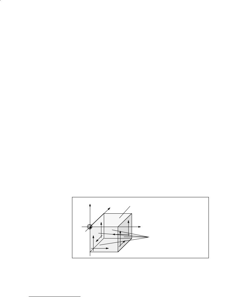
Axis designation1) |
The following axis designations apply to surfaces that are perpendicular |
|
to the design plane: |
Z |
|
Y |
Finished part |
|
|
|
|
||
|
ÀÀ |
Back |
|
|
|
Y1 |
|
|
|
|
ÀÀ |
|
Y1 |
|
|
|
|
|
|
|
ÀÀ |
Y1 |
|
X |
|
Y1 |
|
|
|
|
X1 |
|
Surfaces |
|
|
ÀÀ |
X1 |
|
|
|
|
|
X1 |
perpendicular to |
Left |
ААЙЙЙЙЙЙ |
the design plane |
||
X1 |
|
|
||
|
ЙЙЙЙЙЙЙАА |
|
||
|
|
X1 |
Right |
|
|
ЙЙЙЙЙЙ |
|
||
|
Front |
|
|
|
Bild 1.1 Finished part showing surfaces
J
1) Only if multi-side machining option is available
Siemens AG 1997 All Rights Reserved 6FC5198±VAB00 |
1±1 |
SINUMERIK 840C (BN) |
|

1 Einführung |
11.95 |
1±2 |
Siemens AG 1997 All Rights Reserved 6FC5198±VAB00 |
|
SINUMERIK 840C (BN) |
1106.95
2 Help Function
The function described below provides you with help in almost every operating situation.
By pressing the help key, you activate the help system which is stored in the programming system.
Help in the Graphic
Programming System
s Tools
i Material Help texts concerning the current horizontal softkey functions are available if the first softkey of the horizontal softkey menu shows a green ªi º.
You can obtain graphic help for the various input fields in almost all interactive screenforms. They are not marked specially.
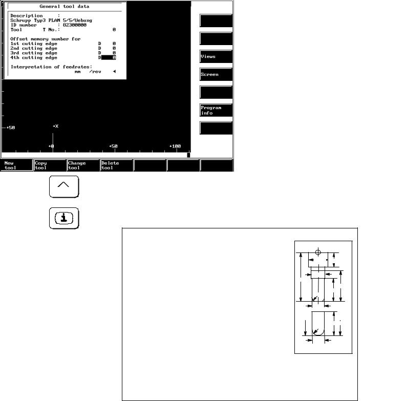
Help texts for the functions in the horizontal softkey menu
If no interactive screen form is displayed, the help system describes the functions of the horizontal softkeys after this key has been pressed.
Bild 2.1 Graphic help for a help screen
The designations F1 to F7 (see Fig. 2.1) refer to the softkeys of the horizontal menu, e.g.:
F1 = Point,
F7 = Edit.
Siemens AG 1997 All Rights Reserved 6FC5198±VAB00 |
2±1 |
SINUMERIK 840C (BN) |
|
2 Help Function |
0711.975 |
Close help screen
Graphic aid for interactive screenforms
If a black triangle appears next to the help text of a softkey, you can press this key to open a further explanatory help screen.
Press this key to close the help screen.
The graphic help for the individual input fields (see Fig. 2.2) is obtained
by pressing the RECALL key.
Press the Help key to display the individual images again.
DS1 |
LS1 |
DT5 |
|
LS |
|
|
LT1 |
CR |
LC1 |
|
|
LS |
LT1 |
CR |
LC1 |
|
|
DT1 |
# 155 |
|
Bild 2.2 Graphic help
J
2±2 |
Siemens AG 1997 All Rights Reserved 6FC5198±VAB00 |
|
SINUMERIK 840C (BN) |
11.95
3 Operation
This manual mainly describes the operator control concepts and the operator control and display elements of the ªGraphic Programming Systemº (GPS) package.
To practice, we advise you to program a workpiece as given in an example (see ªUser's Guide Part 1: Programming Examplesº).
The functions of the keys during graphic programming are explained below.
The following sections describe the keys used for
Interactive screenforms
Crosshair control and
Selection
The Graphic Programming System assists operation by supplying information.
Information for operation is displayed below the graphics field.
Siemens AG 1997 All Rights Reserved 6FC5198±VAB00 |
3±1 |
SINUMERIK 840C (BN) |
|
3 Operation |
0711.975 |
3.1 Interactive screenform control
3.1Interactive screenform control
For programming the workpiece or the tools, parameters are necessary.
The Graphic Programming System inserts screenforms in the graphic area.
You are supplied with input fields for entering parameters. You enter these values in interactive mode.
The figure below shows an example.
|
|
|
|
|
|
|
|
|
|
|
|
|
|
|
|
|
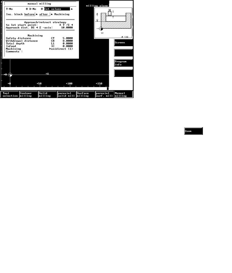
Bild 3.1 Interactive screenform control |
|
|
Interactive screen- |
Every interactive screenform has a name which is displayed in the first |
|
||
form name |
line. In this example, the name is Manual milling. |
|
||
Parameters |
Every interactive screenform contains parameters. A parameter con- |
|
||
|
|
sists of a name and an input field for its values. |
|
|
|
|
In this example, the Total depth is one such parameter. |
|
|
Input field |
An interactive screenform allows parameters to be input. Input fields |
|
||
|
|
are emphasized by colors. The values are input through the alpha nu- |
|
|
|
|
meric keyboard. In this example, these are the fields with the values |
|
|
|
|
ª0.000º. |
|
|
Continuation form |
A continuation form allows several entries to be made for a parameter. |
|
||
|
|
The existence of a continuation form is indicated by a black triangle. |
|
|
|
|
A continuation form can either be an interactive screenform or a selec- |
|
|
|
|
|
||
|
|
tion form. |
|
|
3±2 |
Siemens AG 1997 All Rights Reserved 6FC5198±VAB00 |
|
SINUMERIK 840C (BN) |
0711.957 |
3 Operation |
3.1 Interactive screenform control
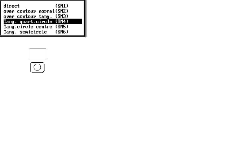
Text selection field A text selection field can be recognized by a black triangle pointing to the left.
In this selection field you can toggle between the individual default texts or make a selection in a selection form.
Selection form |
A selection form is used for selecting certain specific inputs. The possi- |
|
bilities are given by the system. |
|
In our example, an approach strategy for contour milling. |
|
|
|
S |
|
|
Bild 3.2 Selection form
Siemens AG 1997 All Rights Reserved 6FC5198±VAB00 |
3±3 |
SINUMERIK 840C (BN) |
|
3 Operation |
|
|
0911.965 |
3.1 Interactive screenform control |
|
|
|
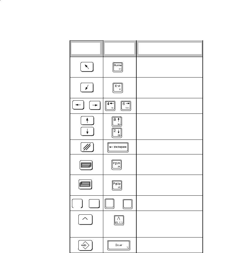
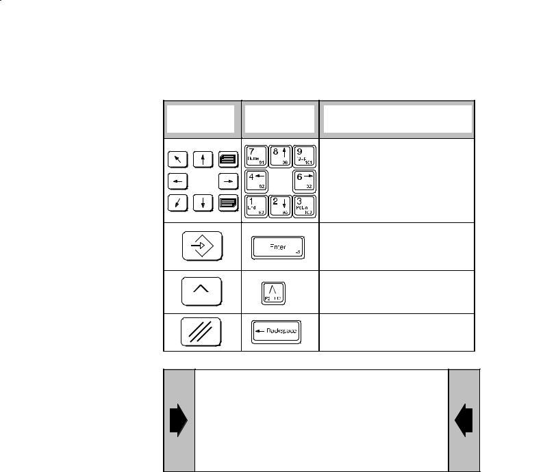
Key functions for |
|
|
|
interactive |
|
|
|
screenform control |
Operator |
Full keyboard |
Function in interactive |
|
panel 840C |
screenforms |
|
|
|
||
|
|
|
With the Home key, you put the |
|
|
|
cursor in the first input field and |
|
|
|
accept the parameters that have |
|
|
|
been input. |
|
|
|
With the End key you go from in- |
|
|
|
put field to input field and accept |
|
|
|
the parameters that have been |
|
|
|
input. |
|
|
|
With these keys, you control the |
|
|
|
cursor within a field when input- |
|
|
|
ting parameters. |
|
|
|
With these keys, you move the |
|
|
|
cursor from input field to input |
|
|
|
field and accept the parameters |
|
|
|
that have been input. |
|
|
|
The CLEAR key deletes the cha- |
|
|
|
racter to the left of the cursor. |
|
|
|
With this key, you move for- |
|
|
|
wards from input field to input |
|
|
|
field and accept the parameters |
|
|
|
that have been input. |
If a black triangle can be seen to the right of the input field, you open a continuation form with this key.
... ... ... |
... ... ... |
You use the alphanumeric keys |
to enter parameters. |
The RECALL key ends interactive screenform input and the system ignores all inputs.
The RECALL key closes the help screens.
With the INPUT key you end screenform inputs and accept all entries.
3±4 |
Siemens AG 1997 All Rights Reserved 6FC5198±VAB00 |
|
SINUMERIK 840C (BN) |
0911.956 |
3 Operation |
|
|
3.1 Interactive screenform control |
|
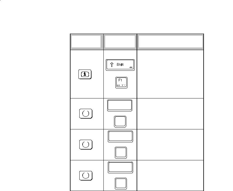
Operator |
Full keyboard |
Function in interactive |
|
panel 840C |
screenforms |
||
|
|||
|
|
With the Help key, you call up a |
|
|
|
screen with help text for each ho- |
|
|
|
rizontal softkey menu. This con- |
|
|
|
tains explanatory texts relating to |
|
|
|
the various softkey functions. |
|
|
|
If an interactive screenform is |
|
|
|
displayed on the screen, you ob- |
|
|
|
tain graphical help for the para- |
|
|
|
meters on pressing this key. |
|
|
Control |
If there is an interactive screen- |
|
|
form on the screen and the cur- |
||
|
58 |
sor is located in an input field, |
|
|
|
||
|
|
you call up a Pocket calculator |
|
|
N |
function with this key. |
|
|
|
||
|
51 |
|
With this key combination or key
Control you combine the work schedule
58
steps to form a block under the function Program steps.
N |
|
|
51 |
|
|
Control |
|
If the cursor is positioned on a |
58 |
text selection field, you can insert |
|
|
the texts one after the other into |
|
|
|
|
|
|
this field using this key combina- |
N |
|
tion or key. This field is indicated |
|
by a black triangle. |
|
51 |
|
Siemens AG 1997 All Rights Reserved 6FC5198±VAB00 |
3±5 |
SINUMERIK 840C (BN) |
|
3 Operation |
0711.975 |
3.2 Selecetion control
3.2Selection control
|
When working with the graphic programming system you will notice that |
|
for some functions operator guidance is provided directly by the keys |
|
described below. |
|
The following options are available |
|
Selection with crosshair, |
|
Direct selection with cursor keys, with operator guidance |
|
Selection directly with the cursor keys, without operator guidance. |
Information line |
The graphic programming system guides you through the programming |
(see Fig. 3.3) |
steps. The operations that you have to carry out are given in an in- |
|
formation line below the graphic area. |
|
An exception to this is the function Oriented geometry. This function |
|
uses the information line also as a log line. |
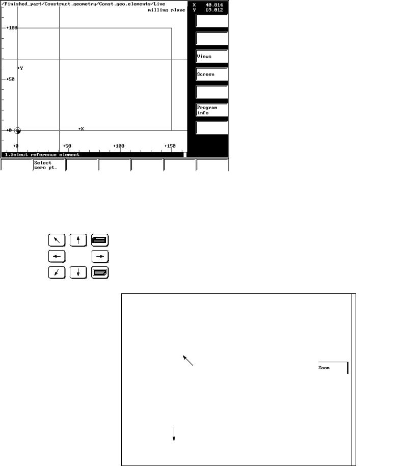
Selection with the With certain functions (such as: Construction geometry/Construct.
crosshair |
elements/Line) the programming system changes over to the operator |
|
guidance mode in which you need the crosshair. |
|
To select geometry elements on the screen, use the control elements |
|
Crosshair. |
|
The diagram below shows an example of this. |
Crosshair
Information line
Bild 3.3 Crosshair control
The operator guidance in the information line tells you to take certain action. The instruction ªSelect first reference elementº refers to the crosshair.
3±6 |
Siemens AG 1997 All Rights Reserved 6FC5198±VAB00 |
|
SINUMERIK 840C (BN) |
0911.956 |
3 Operation |
3.2 Selecetion control
Key functions
Operator |
Full keyboard |
Function with crosshair |
|
panel 840C |
control |
||
|
|||
|
|
You move the crosshair with |
|
|
|
these keys. |
By pressing the INPUT key, you select the element contacted by the crosshair and mark it optically.
By pressing the RECALL key, you end the function and all actions are lost.
You deselect the element last selected by means of the CLEAR key.
When selecting a geometry element with contour, you need not position the crosshair exactly. The programming system automatically finds the element that is closest to the crosshair.
When selecting a point element, you must position the crosshair exactly.
Siemens AG 1997 All Rights Reserved 6FC5198±VAB00 |
3±7 |
SINUMERIK 840C (BN) |
|

3 Operation |
0711.975 |
3.2 Selecetion control
Selection with the When working with the Graphic Programming System, you will find that cursor keys and in certain functions (e.g. when milling) the operator guidance runs im- operator guidance mediately over the keys described below. These keys select or deselect
contours or elements that already exist.
The figure below shows an example of this.
Key functions
3±8
Selected contour colored
Information line
Bild 3.4 Selection control
The operator guidance message in the information line tells you what to do.
Selected contours or elements are marked in color.
Operator |
Full keyboard |
Function with selection |
|
panel 840C |
control |
||
|
|||
|
|
Select the contour with these |
|
|
|
keys. |
The selected element or point is accepted by pressing the INPUT key.
By pressing the INPUT key twice, you activate the function that you wanted for the contour (e.g. Face roughing).
With the RECALL key, you end the function and all actions are lost.
Selected contours or elements are marked in color.
Siemens AG 1997 All Rights Reserved 6FC5198±VAB00
SINUMERIK 840C (BN)
0711.957 |
3 Operation |
|
3.2 Selecetion control |
Selection with the |
The function Oriented geometry (see Section 4.6.1) displays the individ- |
cursor keys without |
ual elements programmed by you in the information line below the |
operator guidance |
graphic area. |
|
An example is given in Fig. 3.5. |
Information line
Bild 3.5 Selection control with cursor keys without operator guidance
The selected construction elements are displayed in a color.
Key functions
Operator |
Full keyboard |
Function in interactive screen- |
|
panel |
form control |
||
|
|||
|
|
With these cursors you move the |
|
|
|
cursor within the information line. |
|
|
|
If a contour element can be dis- |
|
|
|
played it is marked in the graghic |
|
|
|
area. |
|
|
|
You can move the cursor to the |
|
|
|
starting point with the Home key. |
|
|
|
You can move the cursor to the- |
|
|
|
last element with the End key. |
Siemens AG 1997 All Rights Reserved 6FC5198±VAB00 |
3±9 |
SINUMERIK 840C (BN) |
|
3 Operation |
11.95 |
3.3 Other key functions
3.3Other key functions
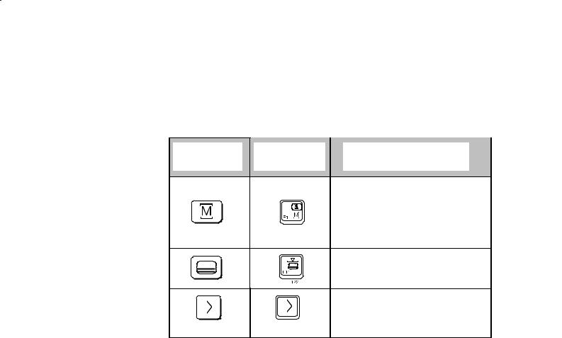
The operator control elements described below apply in all operating situations.
Operator |
Full keyboard |
Function |
panel 840C |
||
|
|
With the MACHINE AREA key, |
|
|
you switch over from any menu |
|
|
into the machine area. The ope- |
|
|
rating status of the window now |
|
|
in the background remains as it |
|
|
is. |
|
|
You extend the horizontal softkey |
|
|
functions with the ETC key. |
|
|
With the Area switchover key, |
|
|
you can put the five areas into |
|
|
the horizontal softkey menu at |
|
|
any time. |
|
|
J |
3±10 |
Siemens AG 1997 All Rights Reserved 6FC5198±VAB00 |
|
SINUMERIK 840C (BN) |
11.95 |
4 Programming Functions |
4 Programming Functions
Section 4 contains
Information about the WOP file environment
Programming notes on the functions on the MMC programming level
Some descriptions of examples of the following WOP functions:
±Tools
±Material
±Geometry
±Machining
±Program steps and
A description of the calculator function.
We recommend you refer to the ªUser's Guide
Part 1: Programming Examplesº.
Starting from a sketch of a workpiece, this Guide documents the individual operations from the definition of the geometry to the creation of the part program.
This ªUser's Guide Part 2: Operating/Programming Functionsº assumes that you have worked through this example and are familiar with the functions of the example.
4.1File environment
While you are programming, the Graphic Programming System uses, changes and creates the following:
Empirical value file (uses)
Part programs (creates)
Program steps as a work schedule (creates)
User magazines (uses, changes, creates)
Master data catalog (uses, changes)
Siemens AG 1997 All Rights Reserved 6FC5198±VAB00 |
4±1 |
SINUMERIK 840C (BN) |
|
4 Programming Functions |
0711.975 |
4.2 Empirical values
4.2Empirical values
Purpose |
The empirical value file is an ASCII file made available to the user (pro- |
||
|
grammer) in which settings and program sequences can be stored by |
||
|
setting variables. The file is executed when the system powers up, thus |
||
|
initiating all entered variables. Any changes made to the empirical value |
||
|
file therefore do not have an effect until the system is initialized. |
||
Notes in |
In addition to the empirical value file there is also a configuring file. |
||
programming |
|
|
|
Configuring file |
The configuring file is an ASCII file available to the machine manufac- |
||
|
turer in which all the machine±dependent data are configured. The file |
||
|
is executed when the system powers up, thus initiating all entered vari- |
||
|
ables. Any changes made to the configuring file therefore do not have |
||
|
an effect until the system is initialized (e.g. with or without multiple sur- |
||
|
face machining). |
||
Empirical value file |
You can edit the empirical value file. |
||
|
|
|
|
|
|
The values for positions, lengths and distances are |
|
|
|
always entered in ºmetricº. |
|
|
|
|
|
|
Anything not located between two vertical lines is interpreted as a com- |
||
|
ment and is ignored. All instructions in ª|º are executed. |
||
|
For example: Part program no. |V1978 = º1º| right. |
||
Operating |
|
|
|
sequences |
|
|
|
The relevant environment description describes how you
call up and
edit
an empirical value file.
You alter the value assignment behind the ª=º sign.
For example: |V831 = 2|
4±2 |
Siemens AG 1997 All Rights Reserved 6FC5198±VAB00 |
|
SINUMERIK 840C (BN) |

0911.956 |
4 Programming Functions |
4.2 Empirical values
Activating altered If an interactive screenform is displayed on the screen and the cursor is empirical values located in an input field you can
Call the calculator function with the toggle key and change the empirical value file or configuring file by entering variables, e.g.: |V1362 = ...|. In this case, the set variables apply immediately and are not reset until the graphic programming system is terminated.
If you have changed the empirical value file using the editor you can activate the variables by
performing a cold restart (power on reset) or ±
activating the softkey functions Read new or Read, original. The empirical values in a file are listed individually below.
Siemens AG 1997 All Rights Reserved 6FC5198±VAB00 |
4±3 |
SINUMERIK 840C (BN) |
|

4 Programming Functions |
0711.975 |
4.2 Empirical values |
|
Contents |
ERFAHRUNGSWERTE und Maskenvorbelegungen für FRAESMA- |
Empirical Values |
SCHINEN |
file |
/EMPIRICAL VALUES and Screen form defaults for MILLING |
|
MACHINES1) |
|
±±±±±±±±±±±±±±±±±±±±±±±±±±±±±±±±±±±±±±±±±±±±±±±±±±±È±±± |
|
Programmanfang /Beginning of program: |
|
±±±±±±±±±±±±±±±±±±±±±±±±±±±±±±±±±±±±± |
|
Programmnummer Vorbesetzung /Program number default |
|
|V1978=º1º| |
|
Maschinenname /Machine name |
|
|V1981=º840C WOP±Mº| |
|
|V928=100| mm |
|
Einschaltstellung Ebene /Flexible Plane Selection: |
|
1 = G17 immer bei Fräsen /G17 fixed for Milling ! |
|
|V812=1| |
|
Einschaltstellung Nullpunkt±Verschiebung |
|
/Zero Offset effective after control power on |
|
1 = G53, 2 = G54, 3 = G55, 4 = G56, 5 = G57 |
|
|V831=2| |
|
Wegbedingung für Programmanfang |
|
/Type of move at the beginning of program |
|
0 = G00, 1 = G01 |
|
|V926=0| |
|
±±±±±±±±±±±±±±±±±±±±±±±±±±±±±±±±±±±±±±±±±±±±±±±±±±±È±±± |
|
Programmende /End of Program: |
|
±±±±±±±±±±±±±±±±±±±±±±±±±±±±± |
|
Ref.±Position anfahren /Travel to machine reference position |
|
2 = nein /no, 1 = ja /yes |
|
|V859=2| |
|
WKZ ±Wechselposition anfahren /Travel to tool change position |
|
2 = nein /no, 1 = ja /yes |
|
|V858=1| |
|
Werkzeug ablegen /Change Tool |
|
2 = nein /no, 1 = ja /yes |
|
|V849=2| |
|
±±±±±±±±±±±±±±±±±±±±±±±±±±±±±±±±±±±±±±±±±±±±±±±±±±±È±±± |
1) The parameters have been taken from the empirical value file of the NC (current date June, 26 1997).
4±4 |
Siemens AG 1997 All Rights Reserved 6FC5198±VAB00 |
|
SINUMERIK 840C (BN) |

0711.957 |
4 Programming Functions |
|
4.2 Empirical values |
Ein± Ausgabesystem Bedienoberfläche
/Input output system user interface:
±±±±±±±±±±±±±±±±±±±±±±±±±±±±±±±±±±±±±
Oberfläche: metrisches oder Inch ± System /User interface: Metric or Inch System
1 |
= metrisch => Einheit Schnittgeschw. in m/min |
|
/metric |
=> Cutting Velocity in m/min |
|
2 |
= Inch |
=> ft/min |
|V1249=1|
NC±Code Ausgabe /NC±code output (1 Inch = 25.4 mm) 1 = Ausgabe in mm /Output in mm (metric system) 25.4 = Ausgabe in Inch /Output in inch
|V1412=1|
Standard±Format für NC±Sätze /Standard format for NC blocs 1 = 3 Nachkommastellen /3 fractional digits
2 = 4 Nachkommastellen /4 fractional digits
3 = 5 Nachkommastellen /5 fractional digits |V1403=1|
±±±±±±±±±±±±±±±±±±±±±±±±±±±±±±±±±±±±±±±±±±±±±±±±±±±È±±±
Funktionen vor Bearbeitung
/Functions before machining operation:
±±±±±±±±±±±±±±±±±±±±±±±±±±±±±±±±±±±±±
Positioniergeschwindigkeit /Axis positioning speed 1 = Eilgang /Rapid traverse
2 = Vorschub /Programmed feedrate |V1105=1|
Zeitpunkt der Funktionsausgabe
/Time of execution of auxiliary functions (M,S,T,H) 1 = keine Ausgabe /no output
2 = vor Anfahren /before travel
3 = am Startpunkt /at start position |V1107=2|
Vorbelegung NPV /Default Zero Offset 1 = aus /None
2 = 1. NPV /1st ZO ± G54
3 = 2. NPV /2nd ZO ± G55
4 = 3. NPV /3rd ZO ± G56
5 = 4. NPV /4th ZO ± G57 |V1108=2|
±±±±±±±±±±±±±±±±±±±±±±±±±±±±±±±±±±±±±±±±±±±±±±±±±±±È±±±
Siemens AG 1997 All Rights Reserved 6FC5198±VAB00 |
4±5 |
SINUMERIK 840C (BN) |
|

4 Programming Functions |
0711.975 |
4.2 Empirical values
Funktionen nach Bearbeitung
/Functions after machining operation :
±±±±±±±±±±±±±±±±±±±±±±±±±±±±±±±±±±±±±
Positioniergeschwindigkeit /Axis positioning speed 1 = Eilgang /Rapid traverse
2 = Vorschub /Programmed feedrate |V1110=1|
Zeitpunkt der Funktionsausgabe
/Time of execution of auxiliary functions (M,S,T,H) 1 = keine Ausgabe /no output
2 = nach Abfahren /after travel |V1112=2|
Vorbelegung NPV /Default zero offset 1 = aus /None
2 = 1. NPV /1st ZO ± G54
3 = 2. NPV /2nd ZO ± G55
4 = 3. NPV /3rd ZO ± G56
5 = 4. NPV /4th ZO ± G57 |V1113=2|
±±±±±±±±±±±±±±±±±±±±±±±±±±±±±±±±±±±±±±±±±±±±±±±±±±±È±±±
Werkzeugeingabe Bohrer+Fräser /Drilling+Milling tool:
±±±±±±±±±±±±±±±±±±±±±±±±±±±±±±±±±±±
Länge Halter /Holder length |V1326=67| [mm]
Durchmesser Halter /Holder diameter |V1327=50| [mm]
Durchmesser Schaft /Shaft diameter |V1328=30| [mm]
______________________________________________________
Werkzeugauswahl /Chuck definition:
±±±±±±±±±±±±±±±±±±±±±±±±±±±±±±±±±±
Magazinausgabe
0 = wie Stammdaten (zweistufig, erst Klasse, dann einzelne Werkzeuge)
/As per Siemens data (two step, first class, individual tools)
1 = direkt (einstufig) /1 = direct (one step) |V1383=1|
±±±±±±±±±±±±±±±±±±±±±±±±±±±±±±±±±±±±±±±±±±±±±±±±±±±È±±±
4±6 |
Siemens AG 1997 All Rights Reserved 6FC5198±VAB00 |
|
SINUMERIK 840C (BN) |

0711.957 |
4 Programming Functions |
4.2 Empirical values
Bohren allgemein /Drilling:
±±±±±±±±±±±±±±±±±±±±±±±±±±±
Ausgabesteuerung Bohrbearbeitung /Output control drilling 1 = aufgelöste Einzelsätze /Single blocks
2 = Steuerungszyklus /Control cycle |V1179=2|
Ausgabesteuerung Zyklus /Output control cycle 1 = als G±Funktion /As G±function
2 = als Unterprogramm /As subroutine
|V1180=1| |
|
|
|
Rückzugsabstand inkrementell zur Bearbeitung |
|
|
|
/Incremental retraction distance from the machined surface |
|
||
|V1117=8| [mm] |
CR |
|
|
Sicherheitsabstand inkrementell zur Bearbeitung |
|
|
|
/Incremental safety clearance from machined surface |
|
|
|
|V1118=5| [mm] |
CT |
|
|
A±Mass Verrechnung (Bohrerspitze) |
|
|
|
/A±dimension calculation (tip of drill) |
|
|
|
1 = ja /yes 0 = nein /no |
|
|
|
|V1181=1| |
Bohren u.Zentrieren / Drilling and center |
|
|
|V1182=1| |
Bohren u.Plansenken / Drilling and spotface |
|
|
|V1206=1| |
Tieflochbohren / Deep hole drilling |
|
|
|V1194=1| |
Gewindebohren /Tapping |
|
|
|V1196=1| |
Ausbohren 1 /Bore 1 |
|
|
|V1198=1| Ausbohren 2 /Bore 2 |
|
|
|
|V1199=1| Ausbohren 3 /Bore 3 |
|
|
|
|V1200=1| Ausbohren 4 /Bore 4 |
|
|
|
|V1204=1| Ausbohren 5 /Bore 5 |
|
|
|
Verweilzeit auf Bohrtiefe in Sekunden |
|
|
|
/Dwell at depth in seconds |
|
|
|
|V1183=2| |
Bohren u.Plansenken / Drilling and spotface |
T2 |
|
|V1186=3| |
Tieflochbohren / Deep hole drilling |
|
T2 |
|V1190=3| Gewindebohren /Tapping |
|
T2 |
|
|V1195=2| Ausbohren 1 /Bore 1 |
|
T1 |
|
|V1197=2| Ausbohren 2 /Bore 2 |
|
T1 |
|
|V1203=4| Ausbohren 4 /Bore 4 |
|
T1 |
|
|V1205=4| Ausbohren 5 /Bore 5 |
|
T1 |
|
±±±±±±±±±±±±±±±±±±±±±±±±±±±±±±±±±±±±±±±±±±±±±±±±±±±È±±±
Siemens AG 1997 All Rights Reserved 6FC5198±VAB00 |
4±7 |
SINUMERIK 840C (BN) |
|

4 Programming Functions |
0711.975 |
4.2 Empirical values
Tieflochbohren /Deep hole drilling: |
|
±±±±±±±±±±±±±±±±±±±±±±±±±±±±±±±±±±± |
|
Erste Bohrtiefe /First drilling depth |
D1 |
|V1184=5| [mm] |
|
Verweilzeit am Anfangspunkt in Sekunden |
T1 |
/Dwell at the starting point in seconds |
|
|V1185=2| |
|
Degression /Degression |
DR |
|V1187=2| |
|
Bohrstrategie /Drilling strategy
1 = Spänebrechen /Chip breaking
2 = Entspanen /Stock removal |V1188=1|
±±±±±±±±±±±±±±±±±±±±±±±±±±±±±±±±±±±±±±±±±±±±±±±±±±±È±±±
Gewindebohren /Tapping:
±±±±±±±±±±±±±±±±±±±±±±±
Zuschlag Sicherheitsebene /Allowance Safety plane |V1189=4| [mm]
Drehrichtung Rückzug /Direction of rotation in retraction 1 = automatisch /automatic
2 = rechts /right
3 = links /left |V1191=1|
Drehrichtung nach Zyklus /Direction of rotation after cycle 1 = automatisch /automatic
2 = rechts /right
3 = links /left |V1192=1|
Gewindebohren zentrisch /Tapping concentric 1 = ohne Geber /without encoder
2 = mit Geber /with encoder
3 = ohne Ausgleichsfutter /rigid tapping |V1193=2|
±±±±±±±±±±±±±±±±±±±±±±±±±±±±±±±±±±±±±±±±±±±±±±±±±±±È±±±
4±8 |
Siemens AG 1997 All Rights Reserved 6FC5198±VAB00 |
|
SINUMERIK 840C (BN) |
 Loading...