


Description of Functions 10/2004 Edition
sinumerik
SINUMERIK 840D/810D/840Di
Special Functions

SINUMERIK 840D/840Di SINUMERIK 810D
Special Functions
Description of Functions
Valid for |
|
|
Control |
Software Version |
|
SINUMERIK 840D powerline |
|
7 |
SINUMERIK 840DE powerline (export variant) |
7 |
|
SINUMERIK 840Di |
|
3 |
SINUMERIK 840DiE (export variant) |
|
3 |
SINUMERIK 810D powerline |
|
7 |
SINUMERIK 810DE powerline (export variant) |
7 |
|
10.04 Edition
3-Axis to 5-Axis |
|
Transformation |
F2 |
Gantry Axes |
G1 |
Cycle Times |
G3 |
Contour Tunnel Monitoring K6 |
|
Axis Couplings and ESR |
M3 |
Setpoint Exchange |
S9 |
Tangential Control |
T3 |
Installation and Activation |
|
of Loadable Compile |
|
Cycles |
TE01 |
Simulation of Compile |
|
Cycles |
TE02 |
Clearance Control |
TE1 |
Analog Axis |
TE2 |
Speed/Torque Coupling, |
|
Master-Slave |
TE3 |
Handling Transformation |
|
Package |
TE4 |
MCS Coupling |
TE6 |
Retrace Support |
TE7 |
Cycle-Clock-Independent |
|
Path-Synchronous Signal |
|
Output |
TE8 |
Preprocessing |
V2 |
3D Tool Radius |
|
Compensation |
W5 |
Index
3ls |
SINUMERIK Documentation |
|
Printing history
Brief details of this edition and previous editions are listed below.
The status of each edition is shown by the code in the “Remarks” column.
Status code in the “Remarks” column:
A . . . . . New documentation.
B . . . . . Unrevised reprint with new order no. C . . . . . Revised edition with new status.
If factual changes have been made on the page in relation to the same software version, this is indicated by a new edition coding in the header on that page.
Edition |
Order No. |
Remarks |
04.95 |
6FC5 297-2AC80-0BP0 |
A |
03.96 |
6FC5 297-3AC80-0BP0 |
C |
08.97 |
6FC5 297-4AC80-0BP0 |
C |
12.97 |
6FC5 297-4AC80-0BP1 |
C |
12.98 |
6FC5 297-5AC80-0BP0 |
C |
08.99 |
6FC5 297-5AC80-0BP1 |
C |
04.00 |
6FC5 297-5AC80-0BP2 |
C |
10.00 |
6FC5 297-6AC80-0BP0 |
C |
09.01 |
6FC5 297-6AC80-0BP1 |
C |
11.02 |
6FC5 297-6AC80-0BP2 |
C |
03.04 |
6FC5 297-7AC80-0BP0 |
C |
08.04 |
6FC5 297-7AC80-0BP1 |
C |
10.04 |
6FC5 297-7AC80-0BP2 |
C |
Trademarks
SIMATICr, SIMATIC HMIr, SIMATIC NETr, SIROTECr, SINUMERIKr and SIMODRIVEr are trademarks of Siemens. Other product names used in this documentation may be trademarks which, if used by third parties, could infringe the rights of their owners.
Further information is available in the Internet under: http://www.siemens.com/motioncontrol
This publication was produced with Interleaf V 7
Other functions not described in this documentation might be executable in the control. However, no claim can be made regarding the availability of these functions when the equipment is first supplied or for service cases.
We have checked that the contents of this document correspond to the hardware and software described. Nonetheless, differences might exist and therefore we cannot guarantee that they are completely identical. The information contained in this document is, however, reviewed regularly and any necessary changes will be included in the next edition. We welcome suggestions for improvement.
Siemens AG, 1995–2004. All rights reserved |
Subject to change without prior notice. |
|
|
Order No. 6FC5 297-7AC80-0BP2 |
Siemens Aktiengesellschaft |
Printed in Germany |
|

1010.04.04
Preface
Notes for the |
The SINUMERIK documentation is sub-divided into 4 parts: |
|
reader |
S |
General Documentation |
|
||
|
S |
User Documentation |
|
S |
Manufacturer/Service documentation |
|
S |
OEM Documentation |
This document is designed for machine tool manufacturers. The brochure contains a detailed description of the scope of functions offered by SINUMERIK control systems.
The function descriptions are only valid for the specific software version or up to the software version specified. You should request valid function descriptions for new software versions. Old function descriptions are only partly applicable for new software versions.
More detailed information about other SINUMERIK 840D/840Di/810D brochures and brochures for all SINUMERIK controllers (e.g. universal interface, measuring cycles, etc.) can be obtained from your local Siemens representative.
Note
It may be possible to run functions that are not described in this document in your controller. This does not, however, represent an obligation to supply such functions with a new control or when servicing.
Hotline |
Should you have any questions about your controller, please contact the follow- |
|
|
ing hotline: |
|
|
A&D Technical Support Tel.: |
+49 (180) 5050 222 |
|
Fax: |
+49 (180) 5050-223 |
|
Internet: http://www.siemens.com/automation/support-request |
|
|
Should you have any questions about the documentation (suggestions, correc- |
|
|
tions), please fax them to: |
|
|
Fax: |
+49 (9131) 98-2176 |
|
E-Mail: motioncontrol.docu@erlf.siemens.de |
|
|
Fax form: See the reply form at the end of the brochure |
|
SINUMERIK |
http://www.siemens.com/motioncontrol |
|
Internet address |
|
|
Siemens AG, 2004. All rights reserved |
v |
SINUMERIK 840D/840Di/810D Description of Functions Special Functions (FB3) – 10.04 Edition |

10.04
10.04
SINUMERIK 840D |
The improved-performance variants |
|
powerline |
S SINUMERIK 840D powerline and |
|
|
||
|
S |
SINUMERIK 840DE powerline |
|
have been available since 09.2001. A list of available powerline modules can |
|
|
be found in Section 1.1 of the Hardware Reference Manual /PHD/. |
|
SINUMERIK 810D |
The improved-performance variants |
|
powerline |
S SINUMERIK 810D powerline and |
|
|
||
|
S |
SINUMERIK 810DE powerline |
|
have been available since 12.2001. A list of available powerline modules can |
|
|
be found in Section 1.1 of the Hardware Reference Manual /PHC/. |
|
Objective |
The function descriptions provide the information required for configuration and |
|
|
installation. |
|
Target groups |
The information contained in the function descriptions is designed for: |
|
|
S |
Design engineers |
|
S PLC programmers creating the PLC user program with the signals listed |
|
|
S Start-up engineers once the system has been configured and set up |
|
|
S Maintenance personnel inspecting and interpreting status signals and |
|
|
|
alarms |
Notes on how to |
It is structured as follows: |
|
use this manual |
S General list of contents of the manual |
|
|
||
S Functional descriptions in alphanumeric order according to the codes used for the Description of Functions
S Appendix with general index
Note
The Description of Functions Basic Machine (Part 1) contains both a general index as well as a reference list, a glossary of terms used and a list of abbreviations and acronyms.
Pages indicated provide the following information:
Part of the Description of Functions / Book / Chapter / Section / Subsection –
Page
vi |
Siemens AG, 2004. All rights reserved |
SINUMERIK 840D/840Di/810D Description of Functions Special Functions (FB3) – 10.04 Edition |

1010.04.04
If you require information on a certain function, you will find the function as well as the code under which the function is organized on the inside title page of the manual.
If you need information about a certain term, please go to the section headed Index in the Appendix and look for the term concerned. The code of the relevant function description, the section number and the page number on which you will find the information you need are listed in this section.
Within each of the Description of Functions in Chapters 4 and 5 you will find definitions of activation criteria, data format, input limits, etc. for the various signals and data definitions.
These definitions are explained in the “Technical information” section below.
Important
! This documentation applies to:
D SINUMERIK 840D powerline control, software version 7
D SINUMERIK 810D powerline control, software version 7
D SINUMERIK 840Di control, software version 3
Equivalent software versions
The software versions specified in this documentation refer to the
SINUMERIK 840D powerline and 810D powerline control systems with the parallel applicable software version. Whether individual functions have been approved for the control systems is not specified explicitly in each case, for further details, see /BU/, Catalog NC 60. The following applies:
Table 1-1 |
Equivalent software version |
|
|
|
|
|
|
|
|
SINUMERIK 840D |
|
SINUMERIK 810D |
SINUMERIK 840Di |
|
powerline |
|
powerline |
|
|
|
|
|
|
|
7.1 |
|
Corresponds |
7.1 |
3.1 |
|
|
to |
|
|
|
|
|
|
|
Siemens AG, 2004. All rights reserved |
vii |
SINUMERIK 840D/840Di/810D Description of Functions Special Functions (FB3) – 10.04 Edition |

10.04
10.04
Explanation of symbols
Important
!This symbol always appears in the documentation when important information is being conveyed.
Ordering data option
In this documentation, you will find this symbol with a reference to an ordering option. The function described is executable only if the control contains the designated option.
Machine manufacturer
This symbol appears in the documentation whenever the machine manufacturer can influence or modify the described functional behavior. Please observe the information provided by the machine manufacturer.
Danger
!Indicates an imminently hazardous situation which, if not avoided, will result in death or serious injury or in substantial property damage.
Warning
!Indicates a potentially hazardous situation which, if not avoided, could result in death or serious injury or in substantial property damage.
Caution
!Used with the safety alert symbol indicates a potentially hazardous situation which, if not avoided, may result in minor or moderate injury or in property damage.
Caution
Used without safety alert symbol indicates a potentially hazardous situation which, if not avoided, may result in property damage.
viii |
Siemens AG, 2004. All rights reserved |
SINUMERIK 840D/840Di/810D Description of Functions Special Functions (FB3) – 10.04 Edition |

1010.04.04
Notice
Used without safety alert symbol indicates a potentially hazardous situation which, if not avoided, may result in an undesirable result or state.
Technical information
Notations |
The following notation and abbreviations are used in this documentation: |
|
S PLC interface signals –> IS “Signal name” (signal data) |
|
E.g.: – IS “MMC-CPU1 ready” (DB10, DBX108.2) i.e. the signal is stored in |
|
data block 10, data byte 108, bit 2. |
|
– i.e. the signals are stored for specific axes/spindles in data blocks 31 |
|
to 48, data block byte 0. |
|
S Machine data –> MD: MD_NAME (German name) |
|
S Setting data –> SD: SD_NAME (German name) |
|
S The symbol “8” means “corresponds to” |
Explanations of abbreviations used in Chap. 4 and 5
Values in the table
Default value
Value range (minimum and maximum)
Effectiveness of changes
In Chapters 4 and 5 of the Description of Functions you will find a description of the data and signals that bear relevance to the function concerned. Terms and abbreviations used in these tabular descriptions are explained below.
The machine data indicated in the Descriptions of Functions are always values for an NCU572.
For the values of the other NCUs (e.g. NCU570, NCU571, NCU573), please refer to the Lists documentation.
References: /LIS/, “Lists”
The machine data is preset to this value during start-up. The symbol “ / ” indicates that the defaults differ for individual channels.
Specifies the input limits. If no value range is specified, the data type determines the input limits and the field is marked “ ”.
When machine data, setting data, etc. are altered, they are not immediately active. The criteria for activating changes are therefore always specified. The following is a list of the possible activation conditions in order of priority:
S |
POWER ON (po) |
“RESET” key on the front panel of the NCU module |
|
|
or by switching the power off/on |
S |
NEW_CONF (cf) |
– “Reconfiguring” of the PLC interface function |
|
|
– “RESET” key on the operator panel, or |
S |
RESET (re) |
“RESET” key on control unit or |
S |
Immediately (im) |
after entry of the value |
Siemens AG, 2004. All rights reserved |
ix |
SINUMERIK 840D/840Di/810D Description of Functions Special Functions (FB3) – 10.04 Edition |

10.04
10.04
Protection level |
Protection levels 0 to 7 have been used. The lock for protection levels 0 to 3 (4 |
||||
|
to 7) can be canceled by entering the correct password (setting correct key- |
||||
|
switch position). The operator only has access to information protected by one |
||||
|
particular level and the levels below it. The machine data is assigned different |
||||
|
protection levels as a standard measure. |
|
|||
|
The table lists write protection levels only. However, read protection levels are |
||||
|
derived from the write protection levels: |
|
|||
|
|
|
|
|
|
|
|
Write protection level |
|
Read protection level |
|
|
|
|
|
|
|
|
|
|
0 |
|
0 |
|
|
|
|
|
|
|
|
|
1 |
|
1 |
|
|
|
|
|
|
|
|
|
2 |
|
4 |
|
|
|
|
|
|
|
References: |
/BA/, “Operator’s Guide” |
|
||
|
|
|
/FB/, A2, “Various Interface Signals” |
||
Unit |
The unit refers to the machine data default setting |
|
|||
|
SCALING_FACTOR_USER_DEF_MASK and |
|
|||
|
SCALING_FACTOR_USER_DEF. |
|
|||
|
The field contains an “–” symbol if the MD is not based on a physical unit. |
||||
Data type |
The following data types are used in the control system: |
||||
|
S |
DOUBLE |
|
|
|
|
|
Real or integer values (values with decimal point or integers) |
|||
|
|
Input limits from +/–4.19*10–307 to +/–1.67*10308 |
|||
|
S |
DWORD |
|
|
|
|
|
Integers |
|
|
|
|
|
Input limits from –2.147*109 to +2.147*109 |
|
||
|
S |
BOOLEAN |
|
|
|
|
|
Possible input values: true or false or 0 or 1 |
|
||
|
S |
BYTE |
|
|
|
|
|
Integers from –128 to +127 |
|
||
|
S |
STRING |
|
|
|
|
|
Consisting of max. 16 ASCII characters (uppercase letters, digits and |
|||
|
|
underscore) |
|
|
|
Data management The PLC interface descriptions in the individual Descriptions of Functions assume a theoretical maximum number of components:
S4 mode groups (associated signals stored in DB11)
S8 channels (associated signals stored in DB21–30)
S31 axes (associated signals stored in DB31–61)
For the number of components actually implemented for each of the software versions, please consult
References: /BU/, “Ordering Information”, Catalog NC 60
J
x |
Siemens AG, 2004. All rights reserved |
SINUMERIK 840D/840Di/810D Description of Functions Special Functions (FB3) – 10.04 Edition |
1010.04.04
SINUMERIK 840D/840Di/810D Description of Functions Special Functions (Part 3)
3-Axis to 5-Axis Transformation (F2)
1 |
Brief Description . . . . . . . . . . . . . . . . . . . . . . . . . . . . . . . . . . . . . . . . . . . . . . . . . . |
3/F2/1-5 |
|
|
1.1 |
5-axis transformation . . . . . . . . . . . . . . . . . . . . . . . . . . . . . . . . . . . . . . . |
3/F2/1-5 |
|
1.2 |
3-axis and 4-axis transformation . . . . . . . . . . . . . . . . . . . . . . . . . . . . . |
3/F2/1-7 |
|
1.3 |
Orientation transformation with swiveling linear axis . . . . . . . . . . . . |
3/F2/1-9 |
|
1.4 |
Universal milling head . . . . . . . . . . . . . . . . . . . . . . . . . . . . . . . . . . . . . . |
3/F2/1-11 |
|
1.5 |
Orientation axes (SW 5.3 and higher) . . . . . . . . . . . . . . . . . . . . . . . . . |
3/F2/1-11 |
|
1.6 |
Cartesian manual travel (SW 6.3 and higher) . . . . . . . . . . . . . . . . . . |
3/F2/1-12 |
|
1.7 |
Cartesian PTP travel (SW 5.3 and higher) . . . . . . . . . . . . . . . . . . . . . |
3/F2/1-12 |
|
1.8 |
Generic 5-axis transformation (SW 5.2 and higher) . . . . . . . . . . . . . |
3/F2/1-12 |
|
1.9 |
Online tool length offset (SW 6.4 and higher) . . . . . . . . . . . . . . . . . . |
3/F2/1-12 |
|
1.10 |
Activation via part program/softkey (SW 5.2 and higher) . . . . . . . . |
3/F2/1-13 |
|
1.11 |
Compression of orientation (SW 6.3 and higher) . . . . . . . . . . . . . . . |
3/F2/1-13 |
2 |
Detailed Description . . . . . . . . . . . . . . . . . . . . . . . . . . . . . . . . . . . . . . . . . . . . . . . |
3/F2/2-15 |
|
|
2.1 |
5-axis transformation . . . . . . . . . . . . . . . . . . . . . . . . . . . . . . . . . . . . . . . |
3/F2/2-15 |
|
2.1.1 |
Kinematic transformation . . . . . . . . . . . . . . . . . . . . . . . . . . . . . . . . . . . |
3/F2/2-15 |
|
2.1.2 |
Machine types for 5-axis transformation . . . . . . . . . . . . . . . . . . . . . . . |
3/F2/2-16 |
|
2.1.3 |
Configuration of a machine for 5-axis transformation . . . . . . . . . . . . |
3/F2/2-18 |
|
2.1.4 |
Tool orientation . . . . . . . . . . . . . . . . . . . . . . . . . . . . . . . . . . . . . . . . . . . . |
3/F2/2-23 |
|
2.1.5 |
Singular positions and handling . . . . . . . . . . . . . . . . . . . . . . . . . . . . . . |
3/F2/2-27 |
|
2.2 |
3-axis and 4-axis transformations . . . . . . . . . . . . . . . . . . . . . . . . . . . . |
3/F2/2-29 |
|
2.3 |
Transformation with swiveled linear axis . . . . . . . . . . . . . . . . . . . . . . |
3/F2/2-31 |
|
2.4 |
Universal milling head . . . . . . . . . . . . . . . . . . . . . . . . . . . . . . . . . . . . . . |
3/F2/2-37 |
|
2.4.1 |
Fundamentals of universal milling head . . . . . . . . . . . . . . . . . . . . . . . |
3/F2/2-37 |
|
2.4.2 |
Parameterization . . . . . . . . . . . . . . . . . . . . . . . . . . . . . . . . . . . . . . . . . . |
3/F2/2-39 |
|
2.4.3 |
Traversal of universal milling head in JOG mode . . . . . . . . . . . . . . . |
3/F2/2-40 |
|
2.5 |
Call and application of 3-axis to 5-axis transformation . . . . . . . . . . . |
3/F2/2-41 |
|
2.6 |
Generic 5-axis transformation (SW 5.2 and higher) . . . . . . . . . . . . . |
3/F2/2-42 |
|
2.6.1 |
Functionality . . . . . . . . . . . . . . . . . . . . . . . . . . . . . . . . . . . . . . . . . . . . . . |
3/F2/2-42 |
|
2.6.2 |
Description of machine kinematics . . . . . . . . . . . . . . . . . . . . . . . . . . . |
3/F2/2-42 |
2.6.3Generic orientation transformation variants (SW 6.1 and higher) . 3/F2/2-43
2.6.4Parameterizing data for orientable toolholders
|
(SW 6.4 and higher) . . . . . . . . . . . . . . . . . . . . . . . . . . . . . . . . . . . . . . . . |
3/F2/2-45 |
2.6.5 |
Online tool length compensation (SW 6.4 and higher) . . . . . . . . . . . |
3/F2/2-48 |
2.6.6 |
Orientation . . . . . . . . . . . . . . . . . . . . . . . . . . . . . . . . . . . . . . . . . . . . . . . . |
3/F2/2-51 |
2.6.7 |
Orientation movements with axis limits (SW 6.1 and higher) . . . . . |
3/F2/2-53 |
2.6.8 |
Singularities of orientation . . . . . . . . . . . . . . . . . . . . . . . . . . . . . . . . . . . |
3/F2/2-54 |
Siemens AG, 2004. All rights reserved |
3/F2/i |
SINUMERIK 840D/840Di/810D Description of Functions Special Functions (FB3) – 10.04 Edition |

10.04
10.04
2.7 |
Compression of orientation (SW 6.3 and higher) . . . . . . . . . . . . . . . |
3/F2/2-56 |
2.8 |
Orientation axes (SW 5.3 and higher) . . . . . . . . . . . . . . . . . . . . . . . . . |
3/F2/2-59 |
2.8.1 |
JOG mode . . . . . . . . . . . . . . . . . . . . . . . . . . . . . . . . . . . . . . . . . . . . . . . . |
3/F2/2-60 |
2.8.2 |
Programming . . . . . . . . . . . . . . . . . . . . . . . . . . . . . . . . . . . . . . . . . . . . . |
3/F2/2-61 |
2.8.3 |
Programmable offset for orientation axes (SW 6.4 and higher) . . . |
3/F2/2-62 |
2.8.4 |
Orientation transformation and orientable toolholders . . . . . . . . . . . |
3/F2/2-64 |
2.8.5 |
Restrictions for kinematics and interpolation . . . . . . . . . . . . . . . . . . . |
3/F2/2-64 |
2.9 Orientation vectors . . . . . . . . . . . . . . . . . . . . . . . . . . . . . . . . . . . . . . . . . 3/F2/2-66
2.9.1Polynomial interpolation of orientation vectors
|
(SW 5.3 and higher) . . . . . . . . . . . . . . . . . . . . . . . . . . . . . . . . . . . . . . . . |
3/F2/2-66 |
2.9.2 |
Rotation of the orientation vector (SW 6.1 and higher) . . . . . . . . . . |
3/F2/2-69 |
2.9.3Extended interpolation of orientation axes (SW 6.1 and higher) . . 3/F2/2-73
|
2.9.4 |
Programming orientation polynomials (SW 7.1 and higher) . . . . . . |
3/F2/2-77 |
3 |
Supplementary Conditions . . . . . . . . . . . . . . . . . . . . . . . . . . . . . . . . . . . . . . . . . |
3/F2/3-79 |
|
|
3.1 |
Availability . . . . . . . . . . . . . . . . . . . . . . . . . . . . . . . . . . . . . . . . . . . . . . . . |
3/F2/3-79 |
4 |
Data Descriptions (MD, SD) . . . . . . . . . . . . . . . . . . . . . . . . . . . . . . . . . . . . . . . . . |
3/F2/4-81 |
|
|
4.1 |
General machine data . . . . . . . . . . . . . . . . . . . . . . . . . . . . . . . . . . . . . . |
3/F2/4-81 |
|
4.2 |
Channelspecific machine data . . . . . . . . . . . . . . . . . . . . . . . . . . . . . . . |
3/F2/4-84 |
|
4.2.1 |
Channel-specific MD for swiveled linear axis . . . . . . . . . . . . . . . . . . . |
3/F2/4-93 |
|
4.2.2 |
Channel-specific MD for universal milling head . . . . . . . . . . . . . . . . . |
3/F2/4-94 |
|
4.2.3 |
MD and SD compression of orientation (SW 6.3) . . . . . . . . . . . . . . . |
3/F2/4-95 |
|
4.2.4 |
Channel-specific MD for orientation axes . . . . . . . . . . . . . . . . . . . . . . |
3/F2/4-96 |
|
4.2.5 |
Machine data for generic 5-axis transformation . . . . . . . . . . . . . . . . |
3/F2/4-100 |
|
4.2.6 |
MD and SD online tool length offset (SW 6.4) . . . . . . . . . . . . . . . . . . |
3/F2/4-102 |
|
4.2.7 |
MD and SD Cartesian manual travel (SW 6.3 and higher) . . . . . . . |
3/F2/4-103 |
|
4.2.8 |
Channel-spec. MD for Cartesian point-to-point travel . . . . . . . . . . . |
3/F2/4-104 |
|
4.3 |
System variable . . . . . . . . . . . . . . . . . . . . . . . . . . . . . . . . . . . . . . . . . . . |
3/F2/4-105 |
5 |
Signal Descriptions . . . . . . . . . . . . . . . . . . . . . . . . . . . . . . . . . . . . . . . . . . . . . . . . |
3/F2/5-107 |
|
|
5.1 |
Channel-specific signals . . . . . . . . . . . . . . . . . . . . . . . . . . . . . . . . . . . . |
3/F2/5-107 |
6 |
Examples . . . . . . . . . . . . . . . . . . . . . . . . . . . . . . . . . . . . . . . . . . . . . . . . . . . . . . . . . |
3/F2/6-109 |
|
|
6.1 |
Example of a 5-axis transformation . . . . . . . . . . . . . . . . . . . . . . . . . . |
3/F2/6-109 |
|
6.2 |
Example of a 3-axis and 4-axis transformation . . . . . . . . . . . . . . . . . |
3/F2/6-113 |
|
6.2.1 |
Example of a 3-axis transformation . . . . . . . . . . . . . . . . . . . . . . . . . . . |
3/F2/6-113 |
|
6.2.2 |
Example of a 4-axis transformation . . . . . . . . . . . . . . . . . . . . . . . . . . . |
3/F2/6-113 |
|
6.2.3 |
Set of machine data and part program (extract) . . . . . . . . . . . . . . . . |
3/F2/6-114 |
|
6.3 |
Example of a universal milling head . . . . . . . . . . . . . . . . . . . . . . . . . . |
3/F2/6-115 |
|
6.4 |
Example for orientation axes (SW 5.3 and higher) . . . . . . . . . . . . . |
3/F2/6-116 |
6.5 Examples for orientation vectors (SW 5.3 and higher) . . . . . . . . . . . 3/F2/6-118 6.5.1 Example for polynomial interpretation of orientation vectors . . . . . . 3/F2/6-118
6.5.2Example for rotations of orientation vector (SW 6.1 and higher) . . 3/F2/6-119
6.6Example for generic 5-axis transformation (SW 5.2 and higher) . . 3/F2/6-120
6.6.1Example for modification of rotary axis motion
(SW 6.1 and higher) . . . . . . . . . . . . . . . . . . . . . . . . . . . . . . . . . . . . . . . . 3/F2/6-121
6.7 Compressor example for orientation (SW 6.3 and higher) . . . . . . . 3/F2/6-122
3/F2/ii |
Siemens AG, 2004. All rights reserved |
SINUMERIK 840D/840Di/810D Description of Functions Special Functions (FB3) – 10.04 Edition |

1010.04.04
7 |
Data Fields, Lists . . . . . . . . . . . . . . . . . . . . . . . . . . . . . . . . . . . . . . . . . . . . . . . . . . |
3/F2/7-123 |
|
|
7.1 |
Interface signals . . . . . . . . . . . . . . . . . . . . . . . . . . . . . . . . . . . . . . . . . . . |
3/F2/7-123 |
|
7.2 |
Setting data . . . . . . . . . . . . . . . . . . . . . . . . . . . . . . . . . . . . . . . . . . . . . . . |
3/F2/7-123 |
|
7.3 |
Machine data . . . . . . . . . . . . . . . . . . . . . . . . . . . . . . . . . . . . . . . . . . . . . |
3/F2/7-124 |
|
7.4 |
Alarms . . . . . . . . . . . . . . . . . . . . . . . . . . . . . . . . . . . . . . . . . . . . . . . . . . . |
3/F2/7-128 |
|
|
|
J |
Siemens AG, 2004. All rights reserved |
3/F2/iii |
SINUMERIK 840D/840Di/810D Description of Functions Special Functions (FB3) – 10.04 Edition |

10.04
Notes
3/F2/iv |
Siemens AG, 2004. All rights reserved |
SINUMERIK 840D/840Di/810D Description of Functions Special Functions (FB3) – 10.04 Edition |
0310.96.04 |
3-Axis to 5-Axis Transformation (F2) |
1.1 5-axis transformation
Brief Description |
1 |
1.15-axis transformation
Functionality |
The “5-axis transformation” machining package (see Section 2.1) is designed |
|
for machining sculptured surfaces with machine tools that have two rotary axes |
|
in addition to the three linear axes X, Y and Z: |
|
This package thus allows an axially symmetrical tool (milling cutter, laser beam) |
|
to be oriented in any desired relation to the workpiece in the machining space. |
|
The path and path velocity are programmed in the same way as for 3-axis tools. |
|
The tool orientation is programmed additionally in the traversing blocks. |
|
The real-time transformation performs the calculation of the resulting motion of |
|
all 5 axes. The generated machining programs are therefore not machine |
|
specific. Kinematic-specific post-processors are not used for the 5-axis |
|
machining operation. |
|
A selection of various transformations is available for adapting the control to |
|
various machine kinematics. Part program commands can be issued in |
|
operation to switch over between two transformations parameterized during |
|
start-up. |
|
This package therefore covers the three possible basic machine configurations |
|
which differ in terms of tool and workpiece orientation. |
|
S Orientation of tool with two-axis swivel head |
|
(machine type 1) |
|
S Orientation of workpiece with two-axis rotary table |
|
(machine type 2) |
|
S Orientation of workpiece and tool with single-axis rotary table and swivel |
|
head |
|
(machine type 3) |
|
The calculation also includes a tool length compensation. |
|
Since the orientation in relation to the workpiece surface is stored in a separate |
|
FRAME, a tool retraction operation with vertical orientation to the workpiece is |
|
also possible. |
Siemens AG, 2004. All rights reserved |
3/F2/1-5 |
SINUMERIK 840D/840Di/810D Description of Functions Special Functions (FB3) – 10.04 Edition |
3-Axis to 5-Axis Transformation (F2) |
03.96 |
||
|
|
|
10.04 |
1.1 5-axis transformation |
|
|
|
Tool orientation |
The tool orientation can be specified in two ways: |
|
|
|
S In relation to machine |
|
|
|
S In relation to workpiece. |
|
|
Machine-related |
The machine-related orientation is dependent on the machine kinematics. |
||
orientation |
|
|
|
Workpiece-related |
The workpiece-related orientation is not dependent on the machine kinematics. |
||
orientation |
It is programmed by means of: |
|
|
|
S |
Euler angles |
|
|
S |
RPY angles |
|
|
S |
Vector components |
|
|
These elements define the direction of the tool in the workpiece coordinate |
||
|
system. It is possible to program a specific component of the tool in its |
|
|
|
orientation to the workpiece. In most cases, this will be a longitudinal axis of the |
||
|
tool with the tool tip (Tool Center Point, TCP), which is also referred to as |
|
|
|
TCP-programming. |
|
|
System variables for |
Part programs and synchronized actions have read access to system variables |
||
orientation |
that provide the following information: |
|
|
|
S End orientation of block (run-in value) |
|
|
|
S Orientation setpoint (SW 6.4 and higher) |
|
|
|
S Actual orientation (SW 6.4 and higher) |
|
|
|
S Angle between setpoint and actual orientation (SW 6.4 and higher) |
|
|
|
S Status for actual orientation variable (SW 6.4 and higher). |
|
|
|
Chapter 4 contains a detailed description of this. |
|
|
Further |
The transformations described in the following sections are to be regarded as |
||
transformations |
special cases of the general 5-axis transformation described above: |
|
|
|
S 3-axis and 4-axis transformations |
|
|
|
|
With 2 or 3 linear axes and one rotary axis. |
|
|
S |
Swiveling linear axis |
|
|
|
One of the rotary axis rotates the 3rd linear axis. |
|
|
S |
Universal milling head |
|
|
|
The two rotary axes are positioned at a configurable angle in relation to one |
|
|
|
another. |
|
For an overview of these functions, please see Sections 1.2 to 1.4; for a more detailed description, see 2.2 to 2.4. Knowledge of the general 5-axis transformation is a prerequisite for all of these transformations.
3/F2/1-6 |
Siemens AG, 2004. All rights reserved |
SINUMERIK 840D/840Di/810D Description of Functions Special Functions (FB3) – 10.04 Edition |
0310.96.04 |
3-Axis to 5-Axis Transformation (F2) |
1.2 3-axis and 4-axis transformation
1.23-axis and 4-axis transformation
Definition |
In contrast to the transformations described in Section 1.1, 3-axis and 4-axis |
|
transformations have the following characteristics: |
S3-Axis Transformation
–Two translatory axes
–One rotary axis.
S4-Axis Transformation
–Three translatory axes
–One rotary axis.
Both types of transformation belong to the orientation transformations. Orientation of the tool must be programmed explicitly. The orientation of the tool is executed in a plane perpendicular to the rotary axis.
z |
z |
B |
B |
Z |
Z |
Y |
Y |
x |
x |
|
|
X |
X |
Fig. 1-1 Schematic diagram of 3-axis transformation
Siemens AG, 2004. All rights reserved |
3/F2/1-7 |
SINUMERIK 840D/840Di/810D Description of Functions Special Functions (FB3) – 10.04 Edition |
3-Axis to 5-Axis Transformation (F2) |
03.96 |
|
10.04 |
1.2 3-axis and 4-axis transformation
Z |
z |
|
y
Y
x
B
 X
X
Fig. 1-2 Schematic diagram of 4-axis transformation with movable workpiece
A detailed description of the possible kinematics for 3-axis and 4-axis transformations can be found in Section 2.2.
3/F2/1-8 |
Siemens AG, 2004. All rights reserved |
SINUMERIK 840D/840Di/810D Description of Functions Special Functions (FB3) – 10.04 Edition |
0310.96.04 |
3-Axis to 5-Axis Transformation (F2) |
1.3Orientation transformation with swiveling linear axis
1.3Orientation transformation with swiveling linear axis
Introduction
Features of machine kinematics
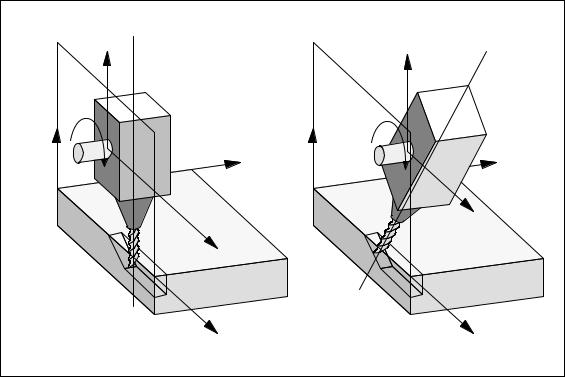
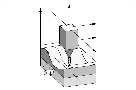
This type of transformation is similar to the 5-axis transformation for machine type 3 described in Section 1.1. However, the 3rd linear axis is not always perpendicular to the plane defined by the other two linear axes.
Machine kinematics, for which the orientation transformation described in the following section applies, can be described as follows:
–Kinematics with three linear axes and two orthogonal rotary axes.
–The rotary axes are parallel to two of the three linear axes.
–The first rotary axis is moved by two Cartesian linear axes. It rotates the third linear axis, which moves the tool. The tool is aligned in parallel to the third linear axis.
–The second rotary axis rotates the workpiece.
–The kinematics comprise a moved workpiece and a moved tool.
The following figure shows the interrelations for one of the possible axis sequences, for which transformation is possible.
Siemens AG, 2004. All rights reserved |
3/F2/1-9 |
SINUMERIK 840D/840Di/810D Description of Functions Special Functions (FB3) – 10.04 Edition |

3-Axis to 5-Axis Transformation (F2) |
03.96 |
|
10.04 |
1.3 Orientation transformation with swiveling linear axis
Swiveled linear axis
+
Z
–
Rotary axis 1
A
+
Workpiece
Workpiece table
– |
X |
+ |
|
|
|
|
|
+Y |
|
|
Rotary axis 2 |
|
+ |
B |
|
– |
|
||
|
|
Machine zero
Fig. 1-3 Schematic diagram of a machine with swivelinglinear axis
3/F2/1-10 |
Siemens AG, 2004. All rights reserved |
SINUMERIK 840D/840Di/810D Description of Functions Special Functions (FB3) – 10.04 Edition |
0410.0.04 |
3-Axis to 5-Axis Transformation (F2) |
1.5 Orientation axes (SW 5.3 and higher)
1.4Universal milling head
Features |
A machine tool with universal milling head is characterized by the following |
|
features: |
|
The machine tool for the universal milling head has at least 5 axes. |
S3 linear axes (for linear motions) [X, Y, Z] move the machining point to any desired position in the machining space.
S2 rotary swivel axes arranged at a configurable angle (usually 45 degrees) allow the tool to swivel to positions in space that are limited to a half sphere in a 45-degree configuration.
1.5Orientation axes (SW 5.3 and higher)
Introduction |
With regard to the kinematics of robots, hexapods or nutators, there is no such |
|
|
simple correlation between axis motion and change in orientation as is the case |
|
|
on conventional 5-axis machines. |
|
|
For this reason, the change in orientation is defined by a model that is created |
|
|
independently of the actual machine. This model defines three virtual orientation |
|
|
axes which can be visualized as rotations about the coordinate axes of a |
|
|
rectangular coordinate system. |
|
|
For the purpose of 6-axis transformation, a third degree of freedom for |
|
|
orientation, describing the rotation of the tool about itself, has been introduced. |
|
Definition |
The Cartesian coordinates are converted from the basic to the machine |
|
|
coordinate system by means of a real-time transformation process. These |
|
|
Cartesian coordinates comprise |
|
|
– |
Geometry axes |
|
– |
Orientation axes |
|
Geometry axes describe the operating point. |
|
|
Orientation axes describe the orientation of the tool in space. |
|
Tool orientation You can define the orientation of the tool in space as follows using linear interpolation, large circle interpolation and by means of orientation vectors:
–Direct Programming of rotary axis positions A, B, C
–For 5-axis transformation by programming:
The Euler or RPY angle in degrees via A2, B2, C2 or the direction vector via A3, B3, C3
–Programming via leading angle LEAD and tilt angle TILT
Siemens AG, 2004. All rights reserved |
3/F2/1-11 |
SINUMERIK 840D/840Di/810D Description of Functions Special Functions (FB3) – 10.04 Edition |
3-Axis to 5-Axis Transformation (F2) |
0811.09921 |
|
10.04 |
1.9 Online tool length offset (SW 6.4 and higher)
1.6Cartesian manual travel (SW 6.3 and higher)
The Cartesian manual travel function allows you to set the:
(for JOG motion) basic coordinate system (BCS),
|
workpiece coordinate system (WCS), |
and the |
tool coordinate system (TCS) |
separately as reference system both for translation and for orientation.
1.7Cartesian PTP travel (SW 5.3 and higher)
|
PTP = Point to Point motion |
Introduction |
This function makes it possible to program a position in a Cartesian coordinate |
|
system (workpiece coordinate system), while the machine traverses in the |
|
machine coordinate system. |
|
The function can be used, for example, to traverse a singularity. Cartesian |
|
positions supplied by a CAD system need not been converted to machine axis |
|
values. |
|
It must also be noted that axes take longer to traverse in the Cartesian |
|
coordinate system with active transformation and programmed feedrate than |
|
when they are traversed directly. |
1.8Generic 5-axis transformation (SW 5.2 and higher)
Introduction |
The generic 5-axis transformation function differs from earlier 5-axis |
|
transformation versions insofar as it is no longer restricted with respect to the |
|
directions of rotary axes. |
|
The basic orientation of the tool is no longer predefined in machine data as was |
|
the case in earlier versions of orientation transformations, but can now be |
|
programmed freely. |
|
Detailed description given in Section 2.6. |
1.9Online tool length offset (SW 6.4 and higher)
Introduction |
You can use the system variable $AA_TOFF[ ] to overlay the effective tool |
|
lengths in 3-D at runtime. These offsets are active for |
|
active orientation transformation (TRAORI) or an |
|
active tool carrier in the relevant tool direction. |
|
If the tool orientation changes, the tool length offsets that apply are rotated so |
|
that the pivot point for the orientation movement always refers to the corrected |
|
tool tip. |
|
Detailed description given in Section 2.6. |
3/F2/1-12 |
Siemens AG, 2004. All rights reserved |
SINUMERIK 840D/840Di/810D Description of Functions Special Functions (FB3) – 10.04 Edition |
11.002.04 |
3-Axis to 5-Axis Transformation (F2) |
1.11Compression of orientation (SW 6.3 and higher)
1.10Activation via part program/softkey (SW 5.2 and higher)
Most of the machine data relevant to kinematic transformations were activated by power ON in earlier versions.
In SW 5.2 and higher, you can also activate transformations MDs via the part program/softkey and it is not necessary to boot the control.
Detailed Description given in
References: /FB/ 2, M1, “Kinematic transformation”, Section 2.5.
1.11Compression of orientation (SW 6.3 and higher)
Solution up to SW 6.1
Solution option in SW 6.3 and higher
During the execution of NC programs containing blocks with relatively short traverse paths, the interpolation time can lead to a reduction in tool path velocity and a corresponding increase in machining time.
You can run NC programs with short traverse paths without reducing the tool path velocity by activating “compressors” COMPON, COMPCURV or COMPCAD. The compressor also smooths the programmed movements and consequently the tool path velocity.
Compressors COMPON, COMPCURV and COMPCAD can only be used in conjunction with special NC blocks in SW up to SW 6.1.
SOnly NC blocks in which the feed is programmed (with F) in addition to the axis motion, are compressed.
SPositions for the axes must be specified directly and cannot be programmed via assignments.
SIn the case of NC programs for 5-axis machines, the tool orientation must be programmed by specifying rotary axis positions in order to activate the compressor.
This means that you can only run 5-axis programs with the compressor if the orientation is programmed directly from the rotary axis motion, independent of the kinematics.
You can program the tool orientation independent of the kinematics by using direction vectors.
NC programs with such direction vectors can be executed with compressors COMPON, COMPCURV and COMPCAD.
You will find a detailed description in Section 2.7.
J
Siemens AG, 2004. All rights reserved |
3/F2/1-13 |
SINUMERIK 840D/840Di/810D Description of Functions Special Functions (FB3) – 10.04 Edition |

3-Axis to 5-Axis Transformation (F2) |
12.98 |
|
10.04 |
1.11 Compression of orientation (SW 6.3 and higher)
Notes
3/F2/1-14 |
Siemens AG, 2004. All rights reserved |
SINUMERIK 840D/840Di/810D Description of Functions Special Functions (FB3) – 10.04 Edition |
0310.96.04 |
3-Axis to 5-Axis Transformation (F2) |
2.1 5-axis transformation
Detailed Description |
2 |
2.15-axis transformation
2.1.1Kinematic transformation
Task of orientation transformation
Fields of application
The task of orientation transformation is to compensate movements of the tool nose, which result from changes in orientation, by means of appropriate compensating movements of the geometry axes. The orientation movement is therefore decoupled from the movement on the workpiece contour. The various machine kinematics each require their own orientation transformation.
The “5-axis transformation” machining package is provided for machine tools, which as well as three linear axes X, Y and Z also have two additional rotary axes (rotation about the linear axes): This package thus allows an axially symmetrical tool (milling cutter, laser beam) to be oriented in any desired relation to the workpiece in every point of the machining space.
The workpiece is always programmed in the rectangular workpiece coordinate system; any programmed or set frames rotate and shift this system in relation to the basic system. The kinematic transformation then converts this information into motion commands of the real machine axes.
The kinematic transformation requires information about the design (kinematics) of the machine, which are stored in machine data.
The kinematic transformation does not act on positioning axes.
Siemens AG, 2004. All rights reserved |
3/F2/2-15 |
SINUMERIK 840D/840Di/810D Description of Functions Special Functions (FB3) – 10.04 Edition |
3-Axis to 5-Axis Transformation (F2) |
10.04 |
2.1 5-axis transformation |
|
2.1.2Machine types for 5-axis transformation
Kinematics of |
5-axis machines are generally equipped with three linear and two rotary axes: |
|
machines for |
the latter may be implemented as a two-axis swivel head, a two-axis rotary table |
|
5-axis |
or as a combination of single-axis rotary table and swivel head. These types of |
|
transformation |
machine are characterized by: |
|
|
1. |
Three linear axes form a right-handed, Cartesian coordinate system. |
|
2. |
Rotary axes are parallel to the traversing direction of one of the linear axes. |
|
|
Example: |
|
|
– A parallel to X |
|
|
– B parallel to Y |
|
|
– C parallel to Z |
|
3. |
Rotary axes are positioned vertically one above the other. |
|
4. |
Rotary axes turn |
|
|
– Tool with two-axis swivel head |
|
|
(machine type 1) |
|
|
– Workpiece with two-axis rotary table |
|
|
(machine type 2) |
|
|
– Tool and workpiece with single-axis rotary table and swivel head |
|
|
(machine type 3) |
|
5. |
The following applies to machine types 1 and 2: |
|
|
– Rotary axis 1 is treated as the 4th machine axis of the transformation. |
|
|
– Motion of 1st rotary axis changes the orientation of the 2nd rotary axis. |
|
|
– Rotary axis 2 is treated as the 5th machine axis of the transformation. |
|
|
– Motion of 2nd rotary axis does not change the orientation of the 1st |
|
|
rotary axis. |
|
6. |
The following applies to machine type 3: |
|
|
– 1st rotary axis (4th machine axis of transformation) turns the tool. |
|
|
– 2nd rotary axis (5th machine axis of transformation) turns the workpiece. |
|
7. |
Initial tool position: |
|
|
– In negative Z direction. |
3/F2/2-16 |
Siemens AG, 2004. All rights reserved |
SINUMERIK 840D/840Di/810D Description of Functions Special Functions (FB3) – 10.04 Edition |

11.002.04 |
3-Axis to 5-Axis Transformation (F2) |
2.1 5-axis transformation
Swivel head, |
Swivel head, |
Swivel head |
|
Z rotatable around |
rotatable |
fixed |
|
X axis and |
around Y axis |
|
|
Z axis |
B |
|
|
C |
|
|
|
|
Y |
|
|
A |
Tool table |
|
Tool table |
rotatable |
|
rotatable |
|
X |
|
||
|
around Z axis |
|
around X axis |
|
Z |
|
and Z axis |
|
C |
Z |
|
|
C |
Y |
|
|
|
|
|
Tool table fixed
|
|
A |
|
|
X |
Rotated tool |
Rotated tool |
Rotated workpiece |
|
Rotated workpiece |
|
Machine type 1 with |
Machine type 3 |
Machine type 2 with |
axis sequence CA |
with axis sequence |
axis sequence AC |
|
BC |
|
Fig. 2-1 Machine types for 5-axis transformation
Machine type 1 Two-axis swivel head
Machine type 2 Two-axis rotary table
Machine type 3 Single-axis swivel head and Single-axis rotary table
Note
Transformations that do not meet all of the above conditions are described in dedicated subsections:
3-axis and 4-axis transformation in 2.2 Swiveling linear axis in 2.3
Universal milling head in 2.4
Siemens AG, 2004. All rights reserved |
3/F2/2-17 |
SINUMERIK 840D/840Di/810D Description of Functions Special Functions (FB3) – 10.04 Edition |
3-Axis to 5-Axis Transformation (F2) |
05.049710 |
|
10.04 |
2.1 5-axis transformation
2.1.3Configuration of a machine for 5-axis transformation
To ensure that the 5-axis transformation can convert the programmed values to axis motions, certain information about the mechanical design of the machine is required; this information is stored in machine data:
SMachine type
SAxis assignment
SGeometry information
SDirection of rotation assignment
Machine type |
The machine types have been designated above as types 1 to 3 and are stored |
||||
|
in machine data |
|
|
|
|
|
$MC_TRAFO_TYPE_1 ... $MC_TRAFO_TYPE_10 |
|
|||
|
as a two-digit number. |
|
|
|
|
|
Table 2-1 gives a list of machine types, which are suitable for 5-axis |
||||
|
transformation. |
|
|
|
|
|
Combinations that are not meaningful whose C axis corresponds to a rotation of |
||||
|
the tool about its longitudinal axis (symmetry axis) are marked by x. |
||||
|
Table 2-1 |
Overview of machine types which are suitable for 5-axis transformation |
|||
|
|
|
|
|
|
|
Machine type |
1 |
2 |
3 |
|
|
|
|
|
|
|
|
Swivel/rotatable |
Tool |
Workpiece |
Tool/workpiece |
|
|
|
|
|
|
|
|
Axis sequence |
|
|
|
|
|
|
|
|
|
|
|
|
|
|
|
|
|
OB |
|
16 |
32 |
48 |
|
|
|
|
|
|
|
AC |
|
x |
33 |
49 |
|
|
|
|
|
|
|
|
|
|
|
|
|
BA |
|
18 |
34 |
50 |
|
|
|
|
|
|
|
BC |
|
x |
35 |
51 |
|
|
|
|
|
|
|
|
|
|
|
|
|
CA |
|
20 |
x |
x |
|
|
|
|
|
|
|
CB |
|
21 |
x |
x |
|
|
|
|
|
|
Identification of |
The axis sequence is identified in the following way: |
|
axis sequence |
S AB means: |
A is 4th axis, B is 5th axis of transformation |
|
||
S For machine type 3, the swivel axis of the tool is the 4th axis of the transformation and the rotary axis of the workpiece is the 5th axis of the transformation.
3/F2/2-18 |
Siemens AG, 2004. All rights reserved |
SINUMERIK 840D/840Di/810D Description of Functions Special Functions (FB3) – 10.04 Edition |
0510.0497.0410 |
3-Axis to 5-Axis Transformation (F2) |
2.1 5-axis transformation
Axis assignment |
The axis assignment at the input of the 5-axis transformation defines which axis |
|
is imaged internally on a channel axis by the transformation. |
|
It is defined in MD: $MC_TRAFO_AXES_IN_1 ... $MC_TRAFO_AXES_IN_10. |
Geometry |
Information concerning the machine geometry is required so that the 5-axis |
information |
transformation can calculate the axis values: This information is stored in the |
|
machine data (in this case, for the first transformation in the channel): |
|
MD: $MC_TRAFO5_PART_OFFSET_1 |
|
Workpiece-oriented offset |
|
S for machine type 1 (two-axis swivel head) |
|
Vector from machine reference point to zero point of table (generally zero |
|
vector) |
|
S for machine type 2 (two-axis rotary table) |
|
Vector from last joint of table to zero point of table |
B
Vector components from last joint to zero point of table
C
Fig. 2-2 Machine data $MC_TRAFO5_PART_OFFSET_1 for machine type 2
Sfor machine type 3 (single-axis swivel head and single-axis rotary table) Vector from joint of rotary table to zero point of table.
MD: $MC_TRAFO5_JOINT_OFFSET_1
Vector from first to second joint (machine type 1 and 2). Vector from machine zero to table joint
(machine type 3).
MD: $MC_TRAFO5_ROT_AX_OFFSET_1
Angle offset of first or second rotary axis
Siemens AG, 2004. All rights reserved |
3/F2/2-19 |
SINUMERIK 840D/840Di/810D Description of Functions Special Functions (FB3) – 10.04 Edition |

3-Axis to 5-Axis Transformation (F2) |
|
|
03.96 |
|
|
|
|
|
10.04 |
2.1 |
5-axis transformation |
|
|
|
|
|
|
DIN symbol for rotary axis |
|
|
C |
|
|
|
|
|
A |
jo |
A |
|
|
|
||
|
|
to |
C |
|
|
|
|
|
|
|
|
t |
|
to |
|
mo |
x |
mo |
t |
|
|
|
|
|
|
|
|
|
x |
Z |
|
|
po |
Tool table |
|
po |
|
|
zero |
|
|
Machine zero |
|
|
|
X |
|
|
|
|
|
|
|
|
Y |
|
|
|
|
Fig. 2-3 Schematic diagram of CA kinematics, moved tool
mo |
Position vector in the MCS |
||||
|
|
|
|
|
$MC_TRAFO5_PART_OFFSET_n[0 ..2] |
po |
|||||
|
|
|
|
Vector of programmed position in the BCS |
|
x |
|||||
t |
Tool compensation vector |
||||
|
|
|
$MC_TRAFO5_BASE_TOOL_n[0 .. 2] |
||
to |
|||||
|
|
$MC_TRAFO5_JOINT_OFFSET_n[0 .. 2] |
|||
jo |
|||||
3/F2/2-20 |
Siemens AG, 2004. All rights reserved |
SINUMERIK 840D/840Di/810D Description of Functions Special Functions (FB3) – 10.04 Edition |
 Loading...