


 General
SPECIFICATIONS
LIFTING
TOWING
LUBRICANTS CONSUMABLES
DRAINING, RE-FILLING
VALUES AND SETTINGS
BA0A - BA0E - BA0F - BA0G - BA0L - BA0U
77 11 176 201 |
APRIL 1995 |
Edition Anglaise |
"The repair methods given by the manufacturer in this document are based on the technical specifications current when it was prepared.
The methods may be modified as a result of changes introduced by the manufacturer in the production of the various component units and accessories from which his vehicles are constructed."
All copyrights reserved by the Regie Nationale des Usines Renault.
Copying or translating, in part or in full, of this document or use of the service part reference numbering system is forbidden without the prior written authority of the Regie Nationale des Usines Renault.
C  Régie Nationale des Usines Renault S.A. 1995
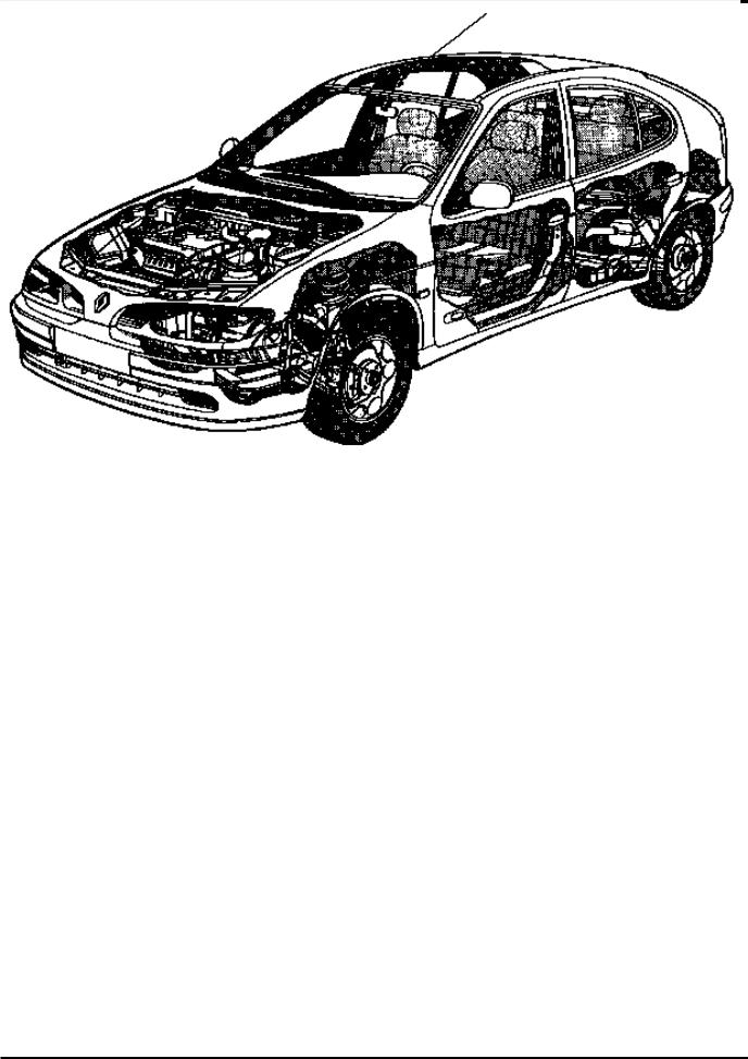
SECTION VIEW
General
Contents
|
|
|
|
Page |
|
|
01 |
SPECIFICATIONS |
|
|
|
|
Engine - Clutch - Gearbox |
01-1 |
|
|
|
Vehicle identification |
01-2 |
|
|
|
|
|
|
|
02 |
LIFTING |
|
|
|
|
Trolley jack - Axle stands |
02-1 |
|
|
|
Vehicle lifts |
02-2 |
|
|
|
|
|
|
|
03 |
TOWING |
|
|
|
|
All types |
03-1 |
|
|
|
|
|
|
|
04 |
LUBRICANTS - CONSUMABLES |
|
|
|
|
Packaging |
04-1 |
|
|
|
|
|
|
|
05 |
DRAINING, RE-FILLING |
|
|
|
|
Engine |
05-1 |
|
|
|
Gearbox |
05-3 |
|
|
|
Power assisted steering |
05-4 |
|
|
|
|
|
|
|
07 |
VALUES AND SETTINGS |
|
|
|
|
Dimensions |
07-1 |
|
|
|
Capacity - Grades |
07-2 |
|
|
|
Belt tension |
07-5 |
|
|
|
Accessories belt tension |
07-7 |
|
|
|
Timing belt tension |
07-13 |
|
|
|
Tightening the cylinder head |
07-15 |
|
|
|
Dimensions of the main braking |
07-17 |
|
|
|
components |
|
|
|
|
Values for checking the front axle |
07-18 |
|
|
|
geometry |
|
|
|
|
Values for checking the rear axle |
07-21 |
|
|
|
geometry |
|
|
|
|
Underbody heights |
07-22 |
|
|
|
Brake limiter |
07-23 |
|
|
|
|
|

SPECIFICATIONS |
01 |
EngineClutch - Gearbox |
Vehicle type |
|
Engine |
Clutch type |
Type of manual gearbox and |
|
|
|
|
|||
Type |
|
Capacity |
automatic transmission |
||
|
|
|
|||
|
|
|
|
||
|
|
|
|
|
|
BA0E |
E7J |
|
1390 |
180 DST 3050 |
JB1 |
|
180 CP 3300 |
||||
|
|
|
|
|
|
BA0F |
K7M |
|
1598 |
200 HR 4000 |
JB1 |
BA0L |
|
||||
|
|
|
|
|
|
BA0G |
F3R |
|
1998 |
215 HRN 4000 |
JB3 |
|
|
|
|
|
|
BA0A |
F8Q |
|
1870 |
200 HRV 4600 |
JB1 |
BA0U |
|
200 HRV 3100 |
|||
|
|
|
|
||
BA0F |
K7M |
|
1598 |
- |
AD4 |
|
|
|
|
|
|
VEHICLE IDENTIFICATION
Example : BA0E
B : Body type (example 5 door hatchback) A : Project code (example 64)
0E : Engine suffix (example E7J 764)
01-1
SPECIFICATIONS |
01 |
|
|
Vehicle identification |
|
||
|
|
|
|
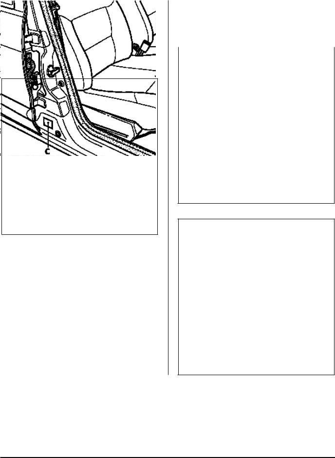
LOCATION OF THE VEHICLE IDENTIFICATION |
• near to the emergency spare wheel (B) with a |
|
|
PLATE |
duplicate label of the oval plate on the lower |
|
|
Two possible locations on the vehicle: |
section of the passenger door (C). |
|
|
|
|
|
|
• in the engine compartment (A), |
|
|
|
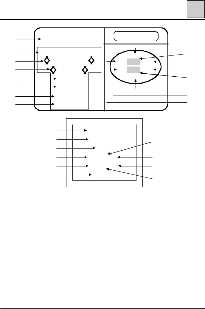
98517R
98485-1R
98516R
01-2
|
SPECIFICATIONS |
01 |
|
|
Vehicle identification |
||
A |
REGIE NATIONALE DES |
|
|
USINES RENAULT S.A. |
|
||
|
8 |
||
B |
e000-00/00000-0000-00 |
|
|
0 0 0 0 |
9 |
||
1 |
VF0000000 |
0 0 0 0 0 0 0 0 |
10 |
2 |
00000000 |
0 0 0 0 0 0 0 0 |
11 |
3 |
0000 kg |
0 0 0 0 0 0 0 |
12 |
4 |
0000 kg |
|
13 |
5 |
1 - 0000 kg |
|
14 |
6 |
2 - 0000 kg |
Renault |
7 |
|
|||
|
1 |
VF0000000 |
|
|
2 |
00000000 |
9 |
|
8 |
0000 |
|
|
7 |
00 000 000 |
10 |
|
14 |
00 000 000 |
11 |
|
13 |
0000000 |
12 |
|
|
|
|
01-3

|
|
|
SPECIFICATIONS |
01 |
|
|
|
|
Vehicle identification |
|
|
|
|
|
|
|
|
It shows: |
the name of the manufacturer, |
|
|
||
At |
A : |
|
|
||
At |
B : |
the E.E.C. approval number |
|
|
|
At |
1 |
: |
the type mines of the vehicle preceded by the world manufacturers identification code (VF1 corre- |
|
|
At |
2 |
: |
sponds to RENAULT FRANCE), |
|
|
the chassis number, |
|
|
|||
At |
3 |
: |
the maximum permissible weight, |
|
|
At |
4 |
: |
the maximum permitted total train weight, |
|
|
At |
5 |
: |
the maximum permitted weight on the front axle, |
|
|
At |
6 |
: |
the maximum permitted weight on the rear axle, |
|
|
At |
7 |
: |
the first figure indicates the gearbox or factory options, |
|
|
At |
8 |
: |
the second figure indicates the equipment level, |
|
|
the vehicle type, |
|
|
|||
At |
9 |
: |
the technical equipment code, |
|
|
At |
10 |
: |
additional factory optional equipment, |
|
|
At |
11 |
: |
the equipment level, |
|
|
At |
12 |
: |
the paint code, |
|
|
At |
13 |
: |
a letter describing the factory of manufacture followed by the fabrication number, |
|
|
At |
14 |
: |
the trim code. |
|
|
NOTE : Depending on the country of export, certain details might not be given. The plate described above shows all possible information.
ALLOCATION OF TECHNICAL EQUIPMENT CODES
The equipment code, the three letters which appear in (9), must be documented for vehicle identification reasons (ordering spare parts, warranty claim, etc.)
01-4
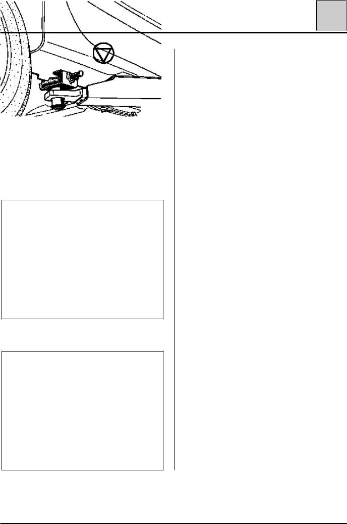
LIFTING |
02 |
Trolley jack - Axle stands |
Safety symbol (special precautions to be taken when carrying out operations).
SPECIAL TOOLING REQUIRED
Cha. 280 -02 |
Adaptable cross piece for trolley |
|
Cha. |
408 -01 |
jack |
|
||
or |
|
Adaptable socket for trolley jack |
Cha. |
408 -02 |
|
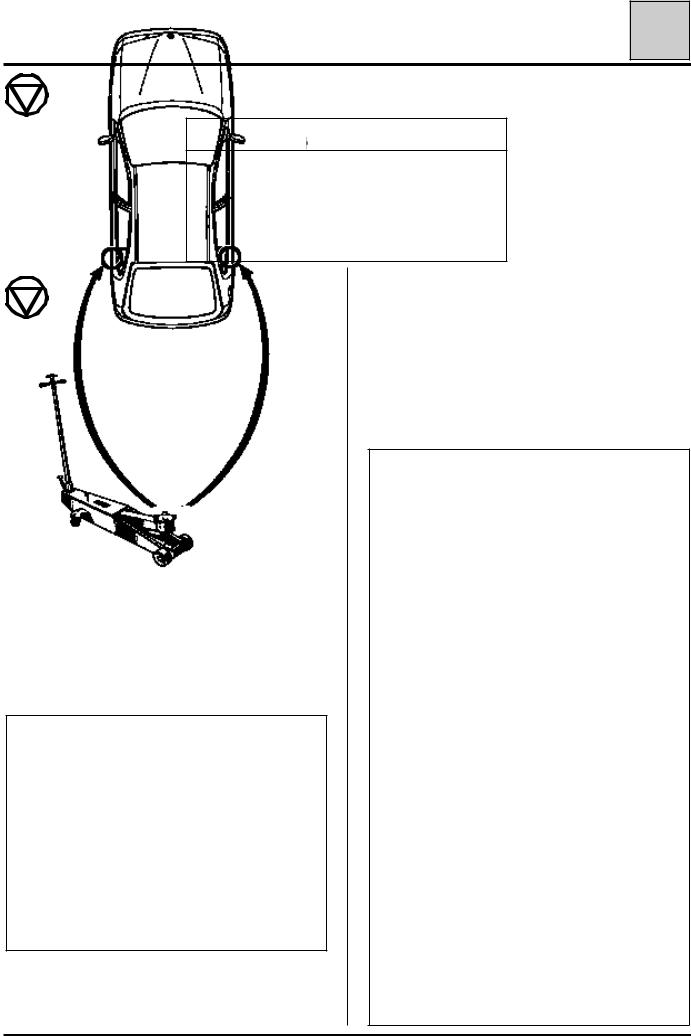
If a trolley jack is used, appropriate axle stands must always be used.
It is forbidden to lift the vehicle by supporting its weight under the front suspension arm or under the V shaped part of the rear axle.
Depending on the type of trolley jack, use sockets
Cha. 408-01 or Cha. 408-02 to position the cross piece Cha. 280-02.
To lift the front or rear, support the vehicle’s weight under the vehicle’s jacking points .
TROLLEY JACK USED FROM THE SIDE
Use cross piece Cha. 280-02.
Take the weight under the sill, level with the front door.
Position the flange correctly in the groove of the cross piece.
AXLE STANDS
When putting the vehicle on axle stands, they must be positioned:
-either under the reinforcements designed for lifting the vehicle using the vehicle’s jack,
-or under the points located behind the reinforcements.
Axle stands are positioned at the rear when the vehicle is lifted from the side.
98699R
85679-1G7
98336G
02-1
LIFTING |
02 |
Vehicle lifts |
SAFETY INSTRUCTIONS
Several scenarios should be considered:
1 - WHEN REMOVING COMPONENTS
In general, never use a 2 post lift, if a four post lift can be used.
If this is not possible, position the lifting pads under the body sill, level with the vehicle’s jacking points.
FRONT
98703S
REAR
98704S
These must be positioned in line with the vehicle’s jacking points. They must be clipped into the holes in the body sill.
2 - SPECIAL CASE - REMOVING AND REFITTING THE ENGINE AND TRANSMISSION ASSEMBLY
In this special case, the body of the vehicle must be firmly attached to the arms of the two post lift using the special pads.
FOG
Reference FOG 449 8111 - 449 8411
or
CHEMICO
Reference 39 2550 0001
or
SCHENCH
Reference 776 684
02-2
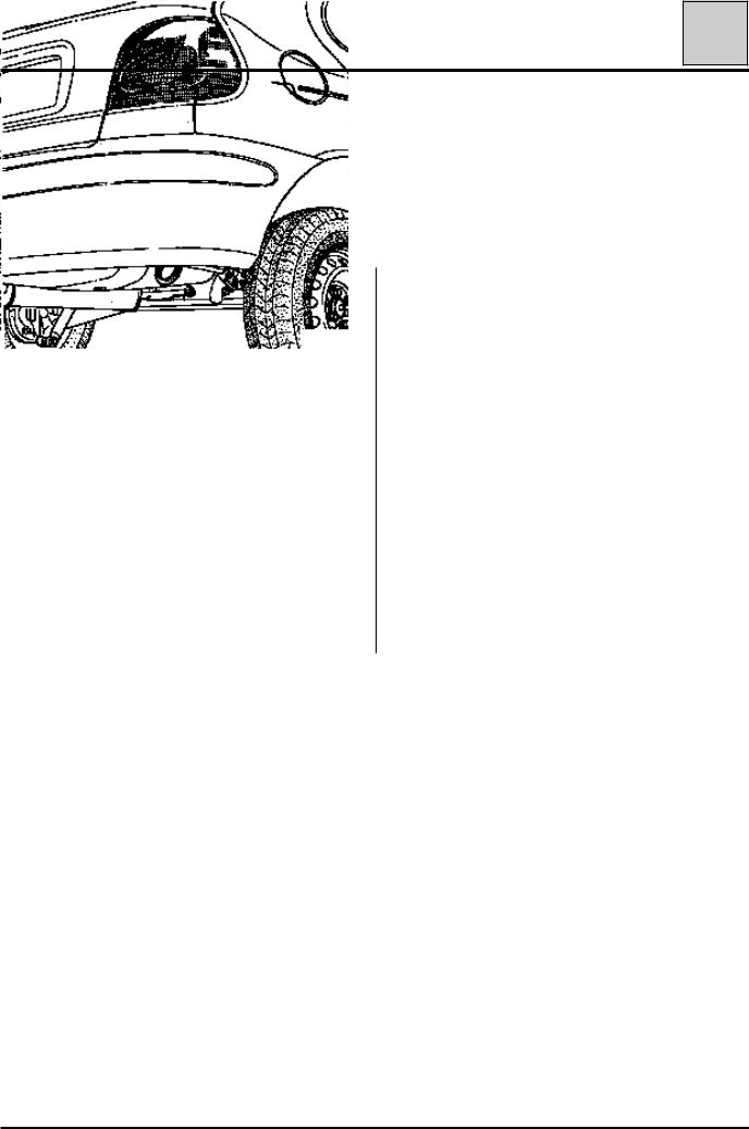
TOWING |
03 |
All types |
OBSERVE THE LEGAL TOWING REQUIREMENTS OF THE COUNTRY YOU ARE IN.
NEVER USE THE DRIVESHAFTS FOR TOWING THE VEHICLE.
The towing points may only be used for towing the vehicle on the road. They should never be used for removing the vehicle from a ditch or for any other similar breakdown operation or to lift the vehicle, either directly or indirectly.
FRONT |
REAR |
98705S |
|
|
98702S |
03-1
|
|
LUBRICANTS - CONSUMABLES |
|
04 |
|
|||
|
|
|
Packaging |
|
|
|||
|
|
|
|
|
|
|
|
|
|
|
|
|
|
|
|
|
|
|
|
DESCRIPTION |
|
PACKAGING |
|
PART NUMBER |
|
|
|
|
|
|
|
|
|
|
|
|
|
|
LUBRICANTS |
|
|
|
||
|
|
|
|
|
|
|
||
|
• MOLYKOTE "BR2" |
|
1 kg tin |
|
77 01 421 145 |
|
|
|
|
|
for main bearing journal faces, thrust pad |
|
|
|
|
|
|
|
|
guide tubes, clutch fork pads, lower suspension |
|
|
|
|
|
|
|
|
arm bearings, torsion bar splines, steering box, |
|
|
|
|
|
|
|
|
driveshaft splines. |
|
|
|
|
|
|
|
• MOLYKOTE "33 Medium" |
|
100 g tube |
|
77 01 028 179 |
|
|
|
|
|
tubular rear axle rings |
|
|
|
|
||
|
|
anti-roll bar rings. |
|
|
|
|
|
|
|
• ANTI-SEIZE |
|
80 ml tube |
|
77 01 422 307 |
|
|
|
|
|
(high temperature grease) Turbo etc. |
|
|
|
|
||
|
• "MOBIL CVJ" 825 Black star |
|
180 g sachet |
|
77 01 366 100 |
|
|
|
|
|
or MOBIL EXF57C |
|
|
|
|
||
|
|
for driveshaft joints |
|
|
|
|
|
|
|
• MULTIPURPOSE LUBRICANT |
|
Aerosol |
|
77 01 422 308 |
|
|
|
|
|
wheel sensor |
|
|
|
|
||
|
|
|
|
|
|
|
|
|
|
|
|
MECHANICAL SEALANTS |
|
|
|
||
|
|
|
|
|
|
|
|
|
|
• |
Perfect-seal "LOWAC" |
|
100 g tube |
|
77 01 417 404 |
|
|
|
|
coating fluid for seals. |
|
|
|
|
|
|
|
• |
Mastic |
|
1.5 kg tin |
|
77 01 421 161 |
|
|
|
|
for sealing exhaust pipe unions. |
|
|
|
|
|
|
|
• HARDENER KIT |
|
Kit |
|
77 01 421 080 |
|
|
|
|
|
("CAF 4/60 THIXO") |
|
|
|
|
|
|
|
|
for sealing sides of bearing caps. |
|
|
|
|
|
|
|
• AUTO joint blue |
|
100 g tube |
|
77 01 396 227 |
|
|
|
|
|
sealing paste. |
|
45 g tube |
|
77 01 397 027 |
|
|
04-1

|
|
LUBRICANTS - CONSUMABLES |
|
04 |
|
|||
|
|
|
Packaging |
|
|
|||
|
|
|
|
|
|
|
|
|
|
|
|
|
|
|
|
|
|
|
|
DESCRIPTION |
|
PACKAGING |
|
PART NUMBER |
|
|
|
|
|
|
|
|
|
|
|
|
|
MECHANICAL SEALANTS |
|
|
|
|||
|
|
|
|
|
|
|
||
|
• AUTO joint grey |
|
100 g tube |
|
77 01 422 750 |
|
|
|
|
|
sealing paste. |
|
|
|
|
|
|
|
• LOCTITE 518 |
|
24 ml syringe |
|
77 01 421 162 |
|
|
|
|
|
for sealing the gearbox housing. |
|
|
|
|
|
|
|
• |
Leak detector |
|
Aerosol |
|
77 11 143 071 |
|
|
|
|
|
|
|
|
|
|
|
|
|
|
ADHESIVES |
|
|
|
||
|
|
|
|
|
|
|
||
|
• "LOCTITE - FRENETANCH" |
|
24 cc bottle |
|
77 01 394 070 |
|
|
|
|
|
stops bolts coming loose and allows them to be |
|
|
|
|
|
|
|
|
undone. |
|
|
|
|
|
|
|
• "LOCTITE - FRENBLOC" |
|
24 cc bottle |
|
77 01 394 071 |
|
|
|
|
|
locks bolts. |
|
|
|
|
|
|
|
• "LOCTITE SCELBLOC" |
|
24 cc bottle |
|
77 01 394 072 |
|
|
|
|
|
for bonding bearings. |
|
|
|
|
|
|
|
• "LOCTITE AUTOFORM" |
|
50 cc bottle |
|
77 01 400 309 |
|
|
|
|
|
for bonding the flywheel to the crankshaft. |
|
|
|
|
|
|
|
|
CLEANING AGENTS - LUBRICANTS |
|
|
|
|||
|
|
|
|
|
|
|
||
|
• "NETELEC" |
|
150 g aerosol |
|
77 01 408 464 |
|
|
|
|
|
unseizes, lubricates. |
|
|
|
|
|
|
|
• |
NC1 cleaner |
|
Aerosol |
|
77 01 422 379 |
|
|
|
|
electrical contact cleaner |
|
|
|
|
|
|
|
• |
Carburettor cleaner |
|
250 ml can |
|
77 01 393 112 |
|
|
|
|
|
|
300 ml aerosol |
|
77 01 393 111 |
|
|
|
• |
Injector cleaner |
|
355 ml can |
|
77 01 423 189 |
|
|
|
• Super concentrated unseizing agent |
|
500 ml aerosol |
|
77 01 408 466 |
|
|
|
|
• "DECAPJOINT " (FRAMET) for cleaning the |
|
Aerosol |
|
77 01 405 952 |
|
|
|
|
|
gasket faces of aluminium cylinder heads |
|
|
|
|
|
|
|
• |
Brake cleaner |
|
400 ml aerosol |
|
77 01 421 282 |
|
|
|
|
|
|
|
|
|
|
|
04-2

|
LUBRICANTS - CONSUMABLES |
|
04 |
|
|||
|
|
Packaging |
|
|
|||
|
|
|
|
|
|
|
|
|
|
|
|
|
|
|
|
|
DESCRIPTION |
|
PACKAGING |
|
PART NUMBER |
|
|
|
|
|
|
|
|
|
|
|
|
VARNISHES |
|
|
|
||
|
|
|
|
|
|
|
|
|
• "CIRCUIT PLUS" |
|
Bottle |
|
77 01 421 135 |
|
|
|
varnish for repairing heated screens |
|
|
|
|
|
|
|
• "CONTACT PLUS" |
|
Kit |
|
77 01 422 752 |
|
|
|
varnish for repairing rear screen supply termi- |
|
|
|
|
|
|
|
nals |
|
|
|
|
|
|
|
|
BRAKES |
|
|
|
||
|
|
|
|
|
|
|
|
|
• Brake fluid |
|
0.5 litre bottle DOT 4 |
|
77 01 421 940 |
|
|
|
|
|
|
|
|
|
|
04-3
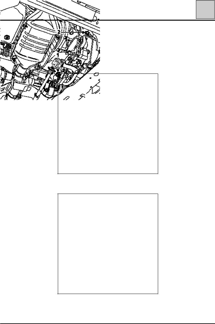
DRAINING, RE-FILLING |
05 |
Engine |
|
|
|
TOOLING REQUIRED |
|
|
|
|
|
|
|
|
|
Engine drain plug spanner |
|
|
|
|
|
|
DRAINING: plug(1) |
FILLING: plug(2) |
|||
F3R - F8Q ENGINES |
F8Q ENGINE |
|||
98486R
E7J - K7M ENGINE
98489R
F3R ENGINE
98701R 98487R
05-1
DRAINING, RE-FILLING |
05 |
Engine |
FILLING: plug(2)
K7M ENGINE
98437R
E7J ENGINE
98700R
05-2
DRAINING, RE-FILLING |
05 |
Gearbox |
DRAINING: plug(1)
FILLING: plug(2)
F3R - F8Q ENGINE
98486R1
E7J - K7M ENGINE
98701R1
05-3
DRAINING, RE-FILLING |
05 |
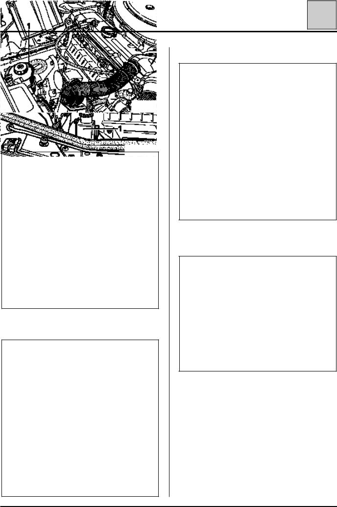
Power assisted steering |
CHECKING THE LEVEL
POWER ASSISTED STEERING PUMP LEVEL
For topping up or filling, use ELF RENAULTMATIC D2 or MOBIL ATF 220 oil.
The level, when correct, should be visible between the MINI and MAXI marks on the reservoir (1).
F8Q ENGINE
98489R1
F3R ENGINE
98487R1
K7M ENGINE
98437R1
E7J ENGINE
98700R1
05-4

VALUES AND SETTINGS |
07 |
Dimensions |
98336R2
*Unladen
**Depending on version Dimensions in metres
07-1
|
|
|
|
|
|
|
VALUES AND SETTINGS |
|
|
|
|
|
07 |
|
||||||||||||
|
|
|
|
|
|
|
Capacity - Grades |
|
|
|
|
|
|
|||||||||||||
|
|
|
|
|
|
|
|
|
|
|
|
|
|
|
|
|
|
|
|
|
|
|
|
|
|
|
|
|
|
|
|
|
|
|
|
|
|
|
|
|
|
|
|
|
|
|
|
|
|
|
|
|
|
|
Components |
|
Capacity |
|
|
|
|
|
|
|
|
Grade |
|
|
|
|
|
|
|
|||||||
|
|
in litres |
|
|
|
|
|
|
|
|
|
|
|
|
|
|
|
|||||||||
|
|
|
|
|
|
|
|
|
|
|
|
|
|
|
|
|
|
|
|
|
|
|
|
|
|
|
|
Petrol engine |
|
After |
E.E.C. countries |
|
|
|
|
|
|
|
|||||||||||||||
|
(oil) |
|
draining |
|
|
|
|
-15°C |
|
|
|
|
|
|
|
|||||||||||
|
|
|
|
|
|
|
|
|
|
|
|
|
|
|
|
|
|
|||||||||
|
|
|
|
|
|
|
|
|
|
|
|
|
|
|
|
|||||||||||
|
|
|
|
|
|
|
-30°C -20°C |
-10°C 0°C +10°C +20 °C |
+30°C |
|
||||||||||||||||
|
|
|
|
|
|
|
|
|
|
|
|
|
|
|
|
|
|
|
|
|
|
|
|
|||
|
|
|
|
|
|
|
|
|
|
|
|
|
|
|
|
|
|
|
|
|
|
|
|
|
||
|
|
|
|
|
|
|
|
|
|
|
|
|
|
|
|
|
|
|
|
|
|
|||||
|
|
|
|
|
|
|
|
|
|
|
|
|
|
|
CCMC-G4 15W40 - 15W50 |
|
|
|||||||||
|
|
|
|
|
|
|
|
|
|
|
|
|
|
|
|
|
|
|
|
|
|
|
|
|
||
|
|
|
|
|
|
|
|
|
|
|
|
|
|
|
|
|
|
|
|
|
|
|
|
|
||
|
|
|
|
|
|
|
|
|
|
|
|
|
CCMC-G5 10W30 - 10W40 - |
|
|
|
|
|
|
|
||||||
|
|
|
|
|
|
|
|
|
|
|
|
|
|
|
|
10W50 |
|
|
|
|
|
|
|
|
|
|
|
|
|
|
|
|
|
|
|
|
|
|
|
|
|
|
|
|
|
|
|
|
|
|
|||
|
|
|
|
|
|
|
|
|
|
|
CCMC-G5 5W30 |
|
|
|
|
|
|
|
|
|
||||||
|
E7J |
|
|
|
|
3,5 |
|
|
|
|
|
|
|
|
|
|
|
|
|
|
|
|
|
|
|
|
|
|
|
|
|
|
|
|
|
CCMC-G5 5W40 - 5W50 |
|
|
|
|
|
|
|
||||||||||
|
|
|
|
|
|
|
|
|
|
|
|
|
|
|
|
|||||||||||
|
K7M |
|
|
|
|
|
|
|
|
|
|
|
|
|||||||||||||
|
|
|
|
|
|
|
|
|
|
|
|
|
||||||||||||||
|
|
|
|
|
|
|
|
|
|
|
|
|
|
|
|
|
|
|
|
|
|
|
|
|
|
|
F3R 5,5
|
Other countries |
|
|
|
|
|
|
|
(plus 0.5 litres |
|
-15°C |
|
|
|
|
|
|
for the oil |
° |
° |
° |
0 |
° |
C |
+10°C +20 °C |
+30°C |
filter) |
-30 C |
-20 C |
-10 C |
|
||||
|
|
|
|
|
|
|
|
|
|
|
|
|
API SG 15W40 |
|
|||
|
|
|
|
API SH 15W40 |
|
|||
|
|
|
|
API SG 10W40 |
|
|||
|
|
|
|
API SH 10W40 |
|
|||
|
|
|
|
API SG 10W30 |
|
|||
|
|
|
|
API SH 10W30 |
|
|||
|
|
|
API SG 5W30 |
|
|
|||
|
|
|
API SH 5W30 |
|
|
|||
07-2
VALUES AND SETTINGS |
07 |
Capacity - Grades |
Components |
Capacity |
|
|
|
Grade |
|
|
|
|
|
|
in litres |
|
|
|
|
|
|
|
|
|||
|
|
|
|
|
|
|
|
|
|
|
|
Diesel engine |
After |
E.E.C. countries |
|
|
|
|
|
|
|
|
|
(oil) |
draining |
|
|
|
|
|
|
|
|
|
|
|
|
|
-15°C |
|
|
° |
|
|
|
|
|
|
|
|
|
|
|
+15 C |
|
|
|
|
|
|
|
-30°C |
-20°C |
-10°C |
0°C |
+10°C |
+20 °C |
|
+30°C |
||
|
|
|
|
CCMC-PD2 15W40 |
|
|
|
||||
|
|
|
|
CCMC-PD2 10W40 |
|
|
|
|
|||
F8Q |
5 |
|
|
|
|
|
|
|
|
|
|
|
|
Other countries |
|
|
|
|
|
|
|
|
|
|
(plus 0.5 litres |
|
|
|
|
|
|
|
|
|
|
|
for the oil |
|
|
° |
|
|
|
° |
|
|
|
|
|
|
|
-15 C |
|
|
|
|
|
|
|
|
filter) |
|
|
|
|
|
+15 C |
|
|
|
|
|
-30°C -20°C -10°C |
0°C |
|
° |
+20 |
° |
C |
° |
|||
|
|
|
|
|
|
+10 C |
|
+30 C |
|||
|
|
|
|
|
API CD 15W40 |
|
|
|
|||
|
|
|
|
|
API CD 10W40 |
|
|
|
|||
|
|
|
|
API CD 10W30 |
|
|
|
|
|
||
07-3
|
|
|
VALUES AND SETTINGS |
07 |
|
||
|
|
|
|
Capacity - Grades |
|
||
|
|
|
|
|
|
|
|
|
|
|
|
|
|
|
|
|
Components |
Capacity in |
|
Grade |
Features |
|
|
|
litres |
|
|
|
|||
|
|
|
|
|
|
|
|
|
Manual gearbox |
|
|
All countries: TRANSELF TRX 75 W 80 W |
|
|
|
|
|
|
|
|
|
||
|
JB1 |
3 .4 |
|
( API GL5 or MIL-L 2105 C or D standards) |
|
|
|
|
|
|
|
|
|
||
|
JB3 |
3 .4 |
|
|
|
|
|
|
|
|
|
|
|
|
|
|
Automatic |
|
|
|
|
|
|
|
transmission |
|
|
ELF RENAULT MATIC D2 (D20104) |
|
|
|
|
|
|
|
|
|
||
|
AD4 |
4 |
|
or use: |
MOBIL ATF 220 (D20104 or D21412) |
|
|
|
|
|
|
|
TEXAMATIC 4011 |
|
|
|
|
|
|
|
|
|
|
|
Brake circuit |
Normal : 0.7 |
|
SAE J 1703 |
Brake fluids must be approved by the Technical |
|
|
|
ABS : 1 |
|
and DOT 3 |
Department |
|
|
|
|
|
|
|
|
|||
|
Fuel tank |
approximately |
|
Unleaded |
|
|
|
|
|
60 |
|
petrol/diesel |
|
|
|
|
Power assisted |
Separate |
|
ELF RENAULT MATIC |
|
|
|
|
steering |
reservoir |
|
D2 or |
|
|
|
|
|
1.1 |
|
MOBIL ATF 220 |
|
|
|
|
|
|
|
|
|
|
|
|
Cooling circuit |
|
|
GLACÉOL RX |
|
|
|
|
F3R |
7 |
|
(type D) |
|
|
|
|
|
Only add coolant |
|
|
|
||
|
F8Q |
7 .5 |
|
|
|
|
|
|
E7J - K7M |
6 |
|
|
|
|
|
|
|
|
|
|
|
|
|
07-4
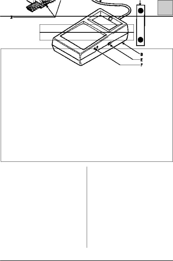
VALUES AND SETTINGS |
07 |
Belt tension |
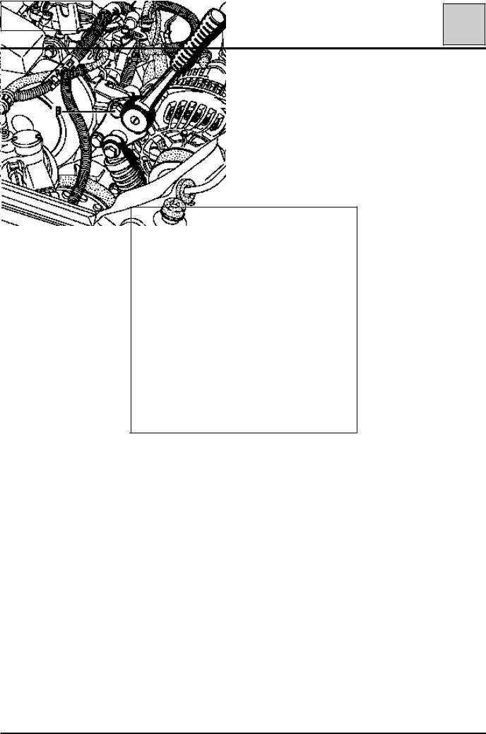
SPECIAL TOOLING REQUIRED
Mot. 1273 Tool for checking belt tension
96601R
ASensor
BDisplay
CConnecting lead
DCalibration checking plate
Principle
The sensor, through the adjusting button (1), the pressure device (2) and the outer lugs (3), applies a constant force to the belt.
The reaction from the belt is measured using a test piece (4) fitted with strain gauges.
Any movement on the gauges creates a variation in their electrical resistance. This variation, once it has been converted by the device, is displayed on the display in SEEM units (US).
Calibrating the device
The device is set in the factory, however it must be recalibrated every six months.
Procedure
Resetting zero:
-switch the device on (button E) with the adjusting button (1) fully screwed in,
-if 0 is displayed, do not touch anything,
-if nothing is displayed, check the condition of the 9 volt battery in the device ,
-if a value other than 0 is displayed, adjust screw
(F) until 0 is displayed.
07-5
VALUES AND SETTINGS |
07 |
Belt tension |
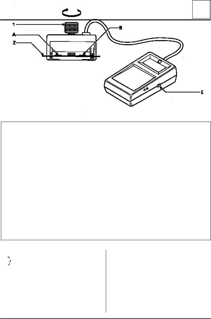
Checking the calibration
Switch the device on (button E).
Position the calibration spring plate (Z) on the sensor as shown on the diagram (checking value engraved towards the top, (A) minimum value, (B) maximum value).
Tighten the adjusting button (1) until it goes "CLICK - CLICK - CLICK".
Check that a value X between the values (A and B) (A ≤ X ≤ B) is displayed.
Note: it may be necessary to perform several preliminary tests in order to obtain the correct value. If the correct value if still not obtained after several attempts, contact SEEM.
NOTE : each device has its own calibration spring plate and they are not interchangeable.
96602R
1 Adjusting button
A Calibration plate checking value
B
Z Calibration plate
SEEM
For further information contact your After Sales Head Office.
GENERAL INSTRUCTIONS:
-Never refit a belt which has been removed, replace it.
-Never retighten a belt for which the tension reading is between the fitting value and the minimum operating value.
-When checking, if the tension is below the minimum operating value, replace the belt.
07-6

VALUES AND SETTINGS |
07 |
Accessories belt tension |
GROOVED BELT
Tensioning process
Engine cold (ambient temperature).
Fit the new belt.
Position the sensor of Mot. 1273.
Turn the adjusting button of the sensor until it disengages (three ’’CLICKS’’).
Tension the belt until the recommended fitting value is displayed on Mot. 1273 .
Lock the tensioner, check it, adjust the value.
Turn the crankshaft over three times.
Check that the tension value is within the fitting tension tolerance, otherwise readjust it.
NOTE :
Never refit a belt which has been removed.
Replace the belt, if the tension is below the minimum operating tension.
Small cuts or cracks do not mean that the belt has to be replaced.
07-7
E7J / K7M ENGINES
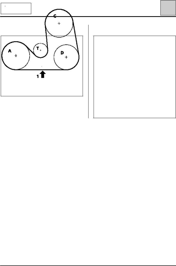
VALUES AND SETTINGS |
07 |
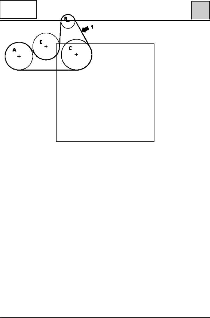
Accessories belt tension |
ALTERNATOR AND POWER ASSISTED STEERING |
AIR CONDITIONING |
98706R
98707R
|
Multitoothed |
Multitoothed |
Multitoothed |
|
Tension |
air |
power assisted |
||
alternator belt |
||||
(US=SEEM unit) |
conditioning |
steering belt |
||
(2) |
||||
|
belt (1) |
(3) |
||
|
|
|||
|
|
|
|
|
Fitting |
110 ± 7 |
84 ± 6 |
84 ± 6 |
|
|
|
|
|
|
Minimum |
75 |
52 |
52 |
|
operating |
||||
|
|
|
ACrankshaft
BAlternator
CPower assisted steering pump
DAir conditioning compressor
T Tensioner
→Tension check point
07-8
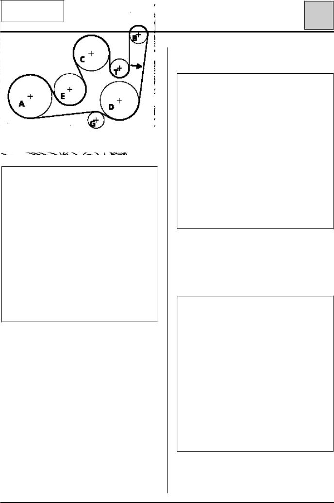
F3R
ENGINE
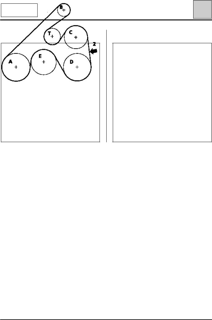
VALUES AND SETTINGS |
07 |
Accessories belt tension |
ALTERNATOR AND POWER ASSISTED STEERING |
AIR CONDITIONING |
98751R 98752R
|
Tension |
Multitoothed |
Multitoothed |
|
air |
power assisted |
|
|
(US=SEEM unit) |
conditioning |
steering belt |
|
|
belt (2) |
(1) |
|
|
|
|
|
Fitting |
109 ± 3 |
107 ± 3 |
|
|
|
|
|
Minimum |
62 |
62 |
|
operating |
||
|
|
|
ACrankshaft
BAlternator
CPower assisted steering pump
DAir conditioning compressor
EWater pump
T Tensioner
→Tension check point
07-9
F8Q ENGINE
Power assisted steering
VALUES AND SETTINGS |
07 |
Accessories belt tension |
ALTERNATOR AND POWER ASSISTED STEERING
98751R
|
Tension |
Multitoothed power |
|
(US=SEEM unit) |
assisted steering belt (1) |
|
|
|
|
Fitting |
97 ± 3 |
|
|
|
|
Minimum operating |
67 |
|
|
|
ACrankshaft
BAlternator
CPower assisted steering pump
EWater pump
T Tensioner
→Tension check point
07-10
F8Q ENGINE
Air conditioning
VALUES AND SETTINGS |
07 |
Accessories belt tension |
SPECIAL NOTES FOR REMOVING THE
ACCESSORIES BELT
REMOVAL
Disconnect the battery.
Before removing the accessories belt, check the value of the tension.
The tension measured must be between 61 and 77
SEEM units.
99706R
ACrankshaft
BAlternator
CPower assisted steering pump
DAir conditioning compressor
EWater pump
G |
Roller |
T |
Tensioner |
→Tension check point
Remove the mounting bolt for the diesel pipe retaining bracket and move it.
98837R2
Slacken bolt (A) then bolt (B), until the shoulder is exceeded, whilst holding the automatic tensioning plate using a 9 mm socket (eg. : FACOM J 151 ratchet), then slacken the belt by moving the ratchet in the direction of the arrow.
98837-1R2
Remove :
-the lower timing cover,
-the belt.
07-11
F8Q ENGINE
Air conditioning
VALUES AND SETTINGS |
07 |
Accessories belt tension |
REFITTING
Refitting is the reverse of removal.
The belt is tensioned by bringing the automatic tensioner up against the bolt (B), without forcing it, using a 9 mm socket (eg. : FACOM J151 ratchet).
98837-1R3
Check the tension of the accessories belt with the previously listed values.
NOTE: never refit a belt which has been removed.
07-12
VALUES AND SETTINGS |
07 |
Timing belt tension |
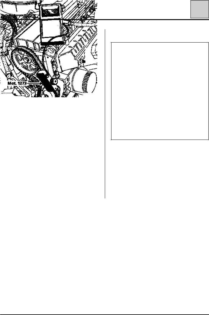
Tensioning process
Engine cold (ambient temperature).
Fit the new belt.
Position the sensor of Mot. 1273.
Turn the adjusting button of the sensor until it disengages (three "CLICKS").
Tension the belt until the recommended fitting value is displayed on Mot. 1273.
Lock the tensioner, check it and adjust the value.
Turn the crankshaft over three times .
Check that the tension value is within the fitting tension tolerance (± 10%), otherwise readjust it.
NOTE :
Never refit a belt which has been removed.
Replace the belt if the tension is below the minimum operating tension.
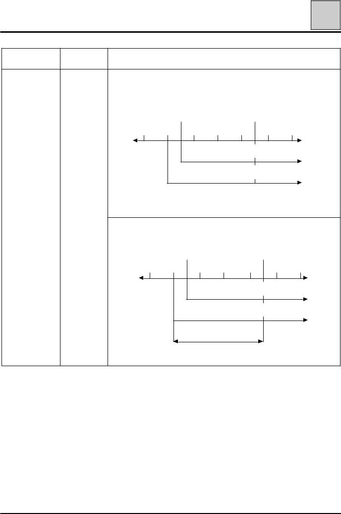
E7J and K7M engine
98708R
Belt tension (in SEEM units)
Fitting: 30 S.U
Minimum operating : 26 S.U.
07-13
 Loading...