


 Loading...
N.T. 3323A
JA0C
Features of the Scénic JA0C fitted with F4R engine
For all parts not dealt with in this Technical Note, refer to Workshop Repair Manual MR 312
77 11 294 602 |
MARCH 2000 |
EDITION ANGLAISE |
"The repair methods given by the manufacturer in this document are based on the technical specifications current when it was prepared.
The methods may be modified as a result of changes introduced by the manufacturer in the production of the various component units and accessories from which his vehicles are constructed."
All copyrights reserved by Renault.
Copying or translating, in part or in full, of this document or use of the service part reference numbering system is forbidden without the prior written authority of Renault.
© RENAULT 2000

Contents
|
|
Page |
|
|
|
02 |
LIFTING |
|
|
Underbody lifts |
02-1 |
|
||
|
|
|
07 |
VALUES AND SETTINGS |
|
|
Capacities - Grades |
07-1 |
|
||
|
Accessories belt tension |
07-3 |
|
Procedure for tensioning the timing belt |
07-4 |
|
Tightening the cylinder head |
07-26 |
|
Tyres and wheels |
07-27 |
|
Brakes |
07-28 |
|
Underbody height |
07-29 |
|
Front axle angle checking values |
07-30 |
|
Rear axle angle checking values |
07-31 |
|
|
|
10 |
ENGINE AND PERIPHERALS |
|
|
Identification |
10-1 |
|
||
|
Oil pressure |
10-2 |
|
Engine - gearbox assembly |
10-3 |
|
Sump |
10-10 |
|
|
|
11 |
TOP AND FRONT OF ENGINE |
|
|
Timing belt |
11-1 |
|
||
|
Cylinder head gasket |
11-9 |
|
|
|
12 |
FUEL MIXTURE |
|
|
Technical specifications |
12-1 |
|
||
|
Air filter unit |
12-4 |
|
Inlet manifold |
12-5 |
|
Injector holder shims |
12-6 |
|
Exhaust manifold |
12-8 |
|
|
Page |
|
|
|
14 |
ANTIPOLLUTION |
|
|
Fuel vapour rebreathing |
14-1 |
|
||
|
|
|
16 |
STARTING - CHARGING |
|
|
Alternator |
16-1 |
|
||
|
Starter motor |
16-3 |
|
|
|
17 |
INJECTION |
|
|
Technical specifications |
17-1 |
|
||
|
Immobiliser function |
17-2 |
|
Injection/Air conditioning diagram |
17-3 |
|
Idle speed correction |
17-4 |
|
Richness regulation |
17-5 |
|
Adaptive richness correction |
17-7 |
|
Camshaft dephaser |
17-8 |
|
Central coolant management GCTE |
17-9 |
|
Computer |
17-10 |
|
Features of the "On Board Diagnostic" |
|
|
system |
17-11 |
|
Illumination conditions of the "On Board |
|
|
Diagnostic" light |
17-12 |
|
Fault finding conditions |
17-13 |
|
Combustion misfire fault finding |
17-14 |
|
Catalytic converter fault finding |
17-15 |
|
Oxygen sensor fault finding |
17-16 |
|
|
|
19 |
COOLING SYSTEM |
|
|
Filling - bleeding |
19-1 |
|
||
|
Diagram |
19-2 |
|
Radiator |
19-3 |
|
Water pump |
19-4 |
|
Suspended engine mounting |
19-5 |
|
Fuel tank |
19-6 |
|
Catalytic converter |
19-9 |

Contents
|
|
Page |
|
|
|
20 |
CLUTCH |
|
|
Mechanism - Plate |
20-1 |
|
||
|
|
|
21 |
MANUAL GEARBOX |
|
|
Identification |
21-1 |
|
||
|
Ratios |
21-1 |
|
Capacity - Lubricants |
21-2 |
|
Gearbox (Removal - Refitting) |
21-3 |
|
Differential cover seal |
21-10 |
|
5th gear housing seal |
21-12 |
|
|
|
26 |
FINAL DRIVE |
|
|
General - Identification |
26-1 |
|
||
|
Final drive (Removal - Refitting) |
26-2 |
|
Viscous coupling |
26-5 |
|
Tapered torque seal |
26-6 |
|
Input shaft seal |
26-8 |
|
Transverse driveshaft seal |
26-10 |
|
Final drive differential cover seal |
26-13 |
|
|
|
29 |
TRANSMISSION |
|
|
Transverse driveshaft |
29-1 |
|
||
|
Longitudinal driveshaft |
29-4 |
|
|
Page |
|
|
|
31 |
FRONT AXLE |
|
|
Sub-frame |
31-1 |
|
||
|
|
|
33 |
REAR AXLE |
|
|
Stabiliser bar |
33-1 |
|
||
|
Shock absorber |
33-2 |
|
Spring |
33-3 |
|
Rear suspension arm |
33-5 |
|
Wheel bearing |
33-8 |
|
Sub-frame |
33-10 |
|
|
|
36 |
STEERING |
|
|
Power assisted steering rack |
36-1 |
|
||
|
Retractable shaft |
36-5 |
37 MECHANICAL ELEMENT CONTROLS
Exploded view |
37-1 |
Clutch transmitter cylinder |
37-2 |
Clutch receiver cylinder |
37-4 |
Clutch control pipes |
37-6 |
ELECTRONICALLY CONTROLLED 38 HYDRAULIC SYSTEM
BOSCH ABS |
38-1 |
LIFTING |
02 |
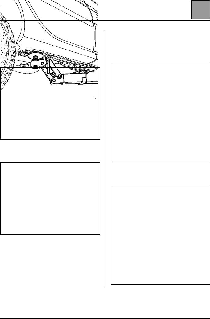
Underbody lifts |
In order to position the lifting pads under the body flange, the edges of the valance protector (A) have to be removed by unclipping them.
Rear protector
18111R
Front protector
18112R
POSITION OF THE LIFTING PADS
Front
18109S
Rear
18110S
02-1

VALUES AND SETTINGS |
07 |
Capacities - Grades |
|
Capacity in |
|
Components |
litres |
Grade |
|
(approx.)* |
|
|
|
|
Petrol engine |
For oil |
Countries in the European Union and Turkey |
(oil) |
changes |
|
|
|
PETROL |
F4R
4.4
4.55 (1)
Standard ACEA A1-98 * Oil for fuel economy
Other countries
When the lubricants specified for the countries of the European Union are not available, the following specifications should be used:
PETROL
Oil for fuel economy:
Standard API SJ-IL SAC GF2
*Adjust using a dipstick
(1) After replacing the oil filter
07-1

|
|
VALUES AND SETTINGS |
|
07 |
||
|
|
Capacities - Grades |
|
|||
|
|
|
|
|
|
|
|
|
|
|
|
|
|
Components |
Capacity in |
Grade |
Special notes |
|||
litres |
||||||
|
|
|
|
|
||
|
|
|
|
|
|
|
Gearbox JC7 |
3.3 |
All countries: TRANSELF TRX 75 W 80 W |
|
|
||
(Standards API GL5 or MIL-L 2105 G or D) |
|
|
||||
|
|
|
|
|||
|
|
|
|
|
|
|
Final drive SD1 |
0.8 |
TRANSELF 80 W 90 |
|
|
|
|
(to be ordered from ELF) |
|
|
|
|||
|
|
|
|
|
||
|
|
|
|
|||
Cooling circuit |
|
Glacéol RX |
Protection to - 20 ˚C ± 2 ˚C for warm, moderate |
|||
7.9 |
and cold climates. |
|
|
|||
F4R |
(type D) |
± 2˚C for very cold climates. |
||||
|
Protection to - 37˚C |
|||||
|
|
|
||||
|
|
|
|
|
|
|
07-2
WITH
AIRCONDITIONING
VALUES AND SETTINGS |
07 |
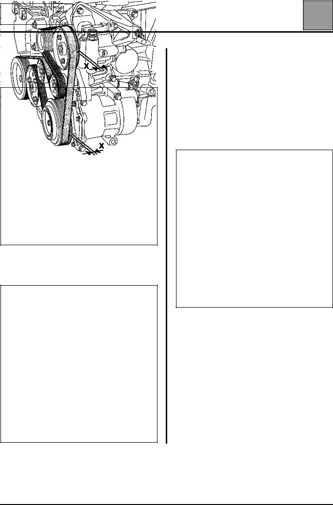
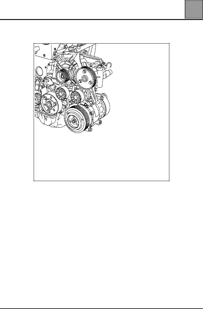
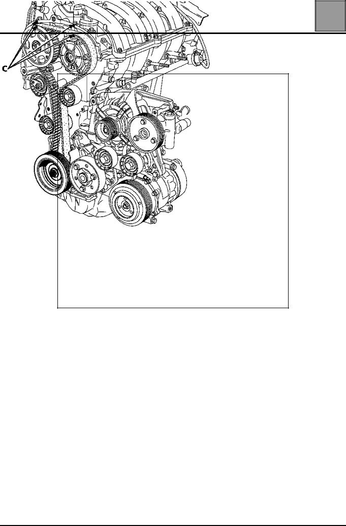
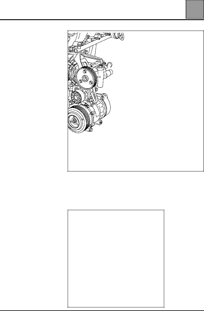
Accessories belt tension |
To remove the belt, pivot the automatic belt tensioner in the direction shown below using a 13 mm angled ring spanner. Tighten the tensioning roller using a
6 mm Allen key (1).
15111R
ALTERNATOR, POWER STEERING AND AIR CONDITIONING
ACrankshaft
BAir conditioning compressor
CAlternator
D Assisted steering pump
E Water pump
FFixed roller
TAutomatic tensioning roller
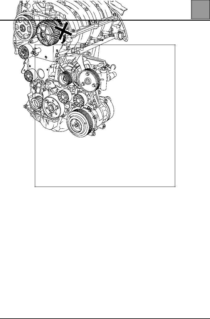
When refitting the belt, it is essential to ensure that the tooth (X) inside the pulleys (timing side) remains "free".
15110R
The engine must be turned through two revolutions in order to position the belt correctly.
15304R
07-3

VALUES AND SETTINGS |
07 |
Timing belt tensioning procedure |
SPECIAL TOOLING REQUIRED
Mot. 799-01 Tool for immobilising pinions on the toothed timing belt
Mot. 1054 Top Dead Centre pin
Mot. 1453 Engine support
Mot. 1496 Tool for setting the camshaft
Mot. 1509 Tool for locking the camshaft pulleys
Mot. 1509-01 Addition to Mot. 1509
Mot. 1517 Tool for fitting inlet camshaft seals
EQUIPMENT REQUIRED
Angular tightening spanner
There are two distinct procedures for setting the timing.
WARNING: the lower timing cover must be fitted before the crankshaft accessories pulley.
1st PROCEDURE
The first procedure is used for replacing all components which require the exhaust camshaft pulley and the inlet camshaft dephaser to be slackened.
During this operation, the following must be replaced:
–the nut of the exhaust camshaft pulley,
–the bolt of the inlet camshaft dephaser,
–the seal of the camshaft dephaser,
–the seal of the dephaser blanking plate.
07-4

VALUES AND SETTINGS |
07 |
Timing belt tensioning procedure |
Method for slackening the exhaust camshaft pulley and the inlet camshaft dephaser.
The operation is performed using tools Mot. 1509 and Mot. 1509-01.
15865R
16014R
Remove the upper toothed pinion from the bracket.
16017S
07-5

VALUES AND SETTINGS |
07 |
Timing belt tensioning procedure |
Fit:
– the spacer (1) of tool Mot. 1509-01 on the stud (2),
16019R
–tool Mot. 1509 as shown on the diagram below, by adjusting the position of the engine using engine support Mot. 1453.
17719-2S
Pivot tool Mot. 1509 until the position shown on the diagram below is reached.
17719-1S
Fit:
–the pinion of tool Mot. 1509-01 (using the two washers and the nut of tool Mot. 1509),
16018S
07-6
VALUES AND SETTINGS |
07 |
Timing belt tensioning procedure |
17719S
–the upper bolt (3) whilst positioning the spacer (4) of tool Mot. 1509-01 between the tool and the camshaft bearing cap housing (do not lock the bolt).
16019-2R
– the shouldered nut (5) of tool Mot. 1509-01.
16019-3R
07-7

VALUES AND SETTINGS |
07 |
Timing belt tensioning procedure |
Tighten the shouldered nut (6) and the bolt (7), then bring the pinions of tool Mot. 1509 into contact with the camshaft pulleys by tightening the nuts (1) to a torque of 8 daN.m.
Remove:
–the blanking plate of the inlet camshaft dephaser using a 14 mm Allen key,
16019-4R2
–the nut of the exhaust camshaft pulley,
–the bolt of the inlet camshaft dephaser.
16019-5S
Replacing the inlet camshaft dephaser seal
Fit the seal of the inlet camshaft dephaser using tool Mot. 1517 and the old bolt (2).
16015-1R
NOTE: to use tool Mot. 1517, the hole must be modified to a diameter of 13 mm.
07-8

VALUES AND SETTINGS |
07 |
Timing belt tensioning procedure |
Adjusting the timing
WARNING:
it is essential to degrease the end of the crankshaft (timing side), the bore and the bearing faces of the timing pinion, the bearing faces of the accessories pulley and the ends of the camshafts (timing side), the bores and the bearing faces of the exhaust camshaft pulley and the inlet camshaft dephaser; to prevent there being any slip between the timing, the crankshaft, the exhaust camshaft pulleys and the inlet dephaser, which may damage the engine.
NOTE:
to make it easier to position the grooves horizontally, position the pulley and dephaser, then tighten the old nut of the pulley and the old bolt of the dephaser to a torque of 1.5 daN.m MAXIMUM.
Check that the pistons are positioned at mid-stroke (to prevent any contact between the valves and the pistons).
Position the grooves of the camshafts horizontally as shown in the diagram below (rotating the camshafts using tool Mot. 799-01 if necessary).
15106-1S
07-9
VALUES AND SETTINGS |
07 |
Timing belt tensioning procedure |
Check that the ring of the camshaft dephaser is correctly locked (no rotation of the ring to the left or to the right).
07-10

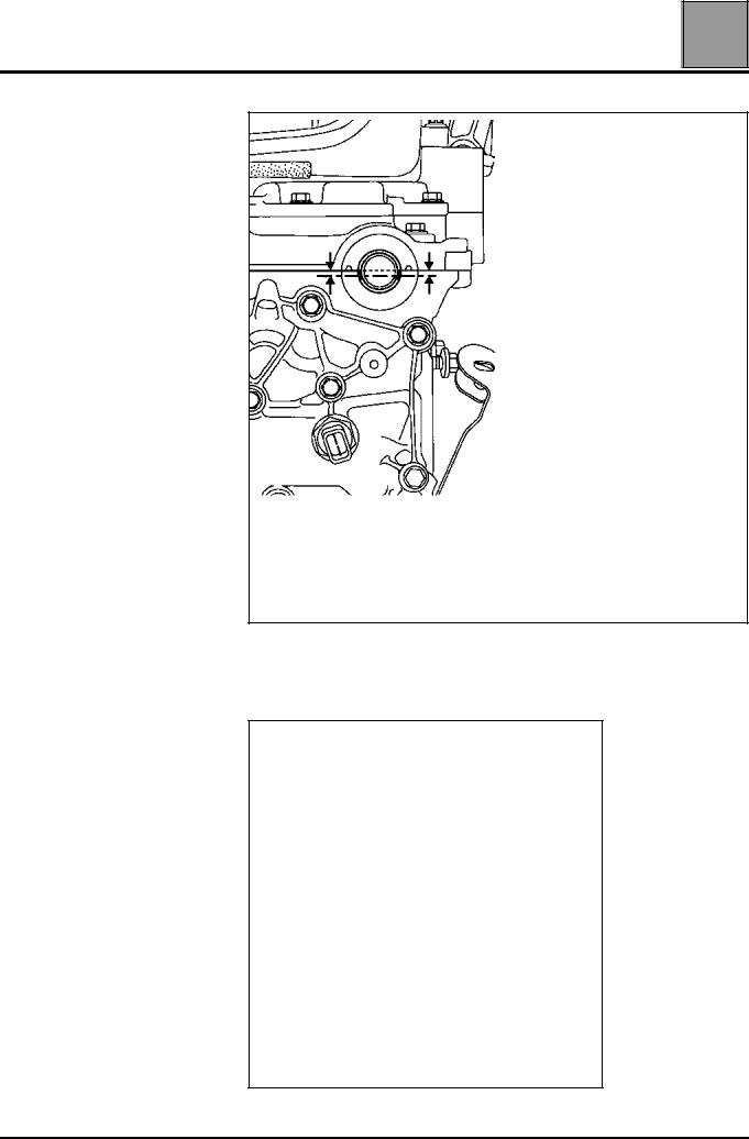
VALUES AND SETTINGS Timing belt tensioning procedure
Position tool Mot. 1496, onto the ends of the camshafts.
15104R
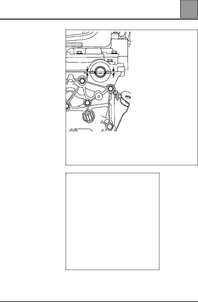
Remove the old nut from the pulley, the old bolt from the dephaser and replace them with a new nut and bolt (leave a clearance of 0.5 - 1 mm between the nut or the bolt and the camshaft pulleys).
Ensure that the crankshaft is correctly pinned at Top Dead Centre and not in the balancing hole (groove (5) of the crankshaft must be positioned in the middle of the two webs (1) of the crankshaft closure panel).
Incorrect position
Pinned crankshaft
15114-1R
 07
07
15163S
15163-1S
07-11
VALUES AND SETTINGS |
07 |
Timing belt tensioning procedure |
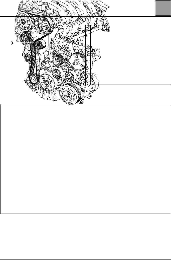
When replacing the timing belt, the tensioning and fixed rollers must be replaced.
Ensure that the lug (1) of the tensioning roller is correctly positioned in the groove (2).
15201R
Refit:
–the timing belt,
–the fixed roller (3) tightening the mounting bolt to a torque of 4.5 daN.m,
–the lower timing cover without tightening the bolts,
–the crankshaft accessories pulley, pre-tightening the bolt (without locking the bolt, clearance of 2 - 3 mm between the bolt and the pulley).
NOTE:
–the crankshaft accessories pulley bolt can be reused if the length under its head does not exceed 49.1 mm (otherwise replace it),
–do not oil the new bolt. However, when reusing the bolt, it must be oiled on the threads and under the head.
07-12

VALUES AND SETTINGS |
07 |
Timing belt tensioning procedure |
Belt tension
Check that there is always a clearance
of 0.5 - 1 mm between the nut, the bolt and the camshaft pulleys.
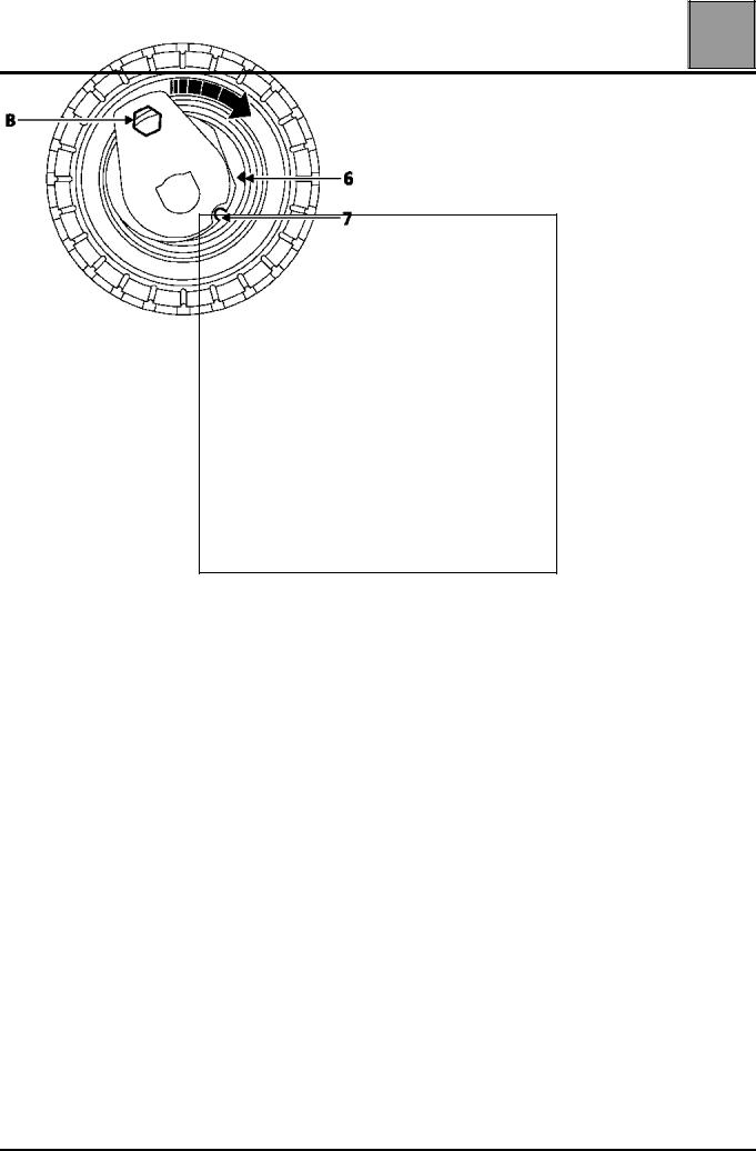
NOTE: do not rotate the tensioning roller in an anti-clockwise direction.
Align the references (6) and (7) of the tensioning roller using a 6 mm Allen key at (B).
15256R
Pre-tighten the nut of the tensioning roller to a torque of 0.7 daN.m.
Rotate the timing through six revolutions in a clockwise direction (timing side) using the exhaust
pulley using tool du Mot. 799-01.
NOTE: check that the nut and the bolt of the camshaft
pulleys do not touch their respective pulleys. To do this, from time to time, push the camshaft pulleys against the camshafts.
Alight the references (6) and (7) if necessary, slackening the nut of the tensioning roller by a maximum of one turn whilst holding it with a 6 mm Allen key. Then tighten the nut finally to a torque of
2.8 daN.m.
Tighten the bolt of the accessories crankshaft pulley to a torque of 2 daN.m (Top Dead Centre pin still positioned in the crankshaft).
07-13
VALUES AND SETTINGS |
07 |
Timing belt tensioning procedure |
Mark a reference (C) using a pencil between the camshaft pulleys and the camshaft bearing cap housing.
15815-8R
REMOVE THE TOP DEAD CENTRE PIN.
07-14

VALUES AND SETTINGS |
07 |
Timing belt tensioning procedure |
Lock the flywheel using a large screwdriver, then turn the bolt of the accessories crankshaft pulley though an angle of 115˚ ± 15˚.
17786S
Pin the crankshaft using the references made previously between the camshaft pulleys and the camshaft bearing cap housing. These references must be aligned, which will ensure that the pin is in the pinning hole and not in the crankshaft balancing hole.
Correct position
15163-1S
Incorrect position
15163S
Fit the tool for locking the camshaft pulleys Mot. 1509 fitted with the additional tool Mot. 1509-01.
Follow the same procedure as when removing.
16019-6S
07-15

VALUES AND SETTINGS |
07 |
Timing belt tensioning procedure |
Tighten the new bolt of the inlet camshaft dephaser to a torque of 10 daN.m.
Tighten the new nut of the exhaust camshaft pulley to a torque of 3 daN.m, then turn through an angle of 90˚ (representing 1/4 of a turn of the nut).
NOTE: as it is not possible to tighten this nut angularly using the angular tightening spanner, this operation will be made easier by making reference points on the pulley and on the nut.
17715S
Remove tool Mot. 1496 for setting the camshaft, tool Mot. 1509 for locking the camshaft pulleys and tool Mot. 1054, the Top Dead Centre pin.
Checking the timing and the tension
Checking the tension:
Rotate the crankshaft through two revolutions in a clockwise direction (timing side), and before the end of
the two revolutions (in other words, before the previously made references are aligned), insert the Top Dead Centre pin (so as to be between the balancing hole and the pinning hole) then put the timing in its setting point.
Before pinning
15163-2S
Pinned crankshaft
15163-1S
Remove the Top Dead Centre pin.
Check that the references of the tensioning roller are correctly aligned, otherwise repeat the tensioning procedure. To do this, slacken the nut of the tensioning roller by a maximum of one turn whilst holding it with a 6 mm Allen key.
Align the references of the tensioning roller and tighten the nut finally to a torque of 2.8 daN.m.
07-16
VALUES AND SETTINGS |
07 |
Timing belt tensioning procedure |
Checking the timing
Ensure that the references of the tensioning roller are in the correct position before checking the setting of the timing.
Fit the Top Dead Centre pin (check that the references made previously on the camshaft pulleys are aligned).
Fit (without forcing) tool Mot. 1496 for setting the camshaft (the camshaft grooves must be horizontal and offset towards the bottom). If the tool cannot be inserted, the timing setting and tensioning procedure must be repeated.
15106-1S
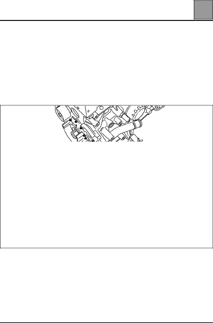
Refit the blanking plate (1) (fitted with a new seal) of the dephaser tightening it to a torque of 2.5 daN.m
15104R
16019-7R
07-17
VALUES AND SETTINGS |
07 |
Timing belt tensioning procedure |
2nd PROCEDURE
The second procedure is used for replacing all components located on the front of the timing which do not require the exhaust camshaft pulley and the inlet camshaft dephaser to be slackened.
Adjusting the timing
WARNING: it is essential to degrease the end of the crankshaft, the bore of the crankshaft pinion and the bearing faces of the crankshaft pulley to prevent any slip between the timing and the crankshaft which may damage the engine.
Position the grooves of the camshafts using tool Mot. 799-01 as shown in the diagram opposite.
15106-1S
Position tool Mot. 1496, onto the ends of the camshafts.
15104R
07-18

VALUES AND SETTINGS |
|
Timing belt tensioning procedure |
|
Ensure that the crankshaft is correctly pinned at |
Pinned crankshaft |
Top Dead Centre and not in the balancing hole |
|
(groove (5) of the crankshaft must be positioned in |
|
|
|
the middle of the two webs (1) of the crankshaft |
|
closure panel). |
|
|
|
Incorrect position
15114-1R
 07
07
15163-1S
15163S
07-19
VALUES AND SETTINGS |
07 |
Timing belt tensioning procedure |
Check that the ring of the camshaft dephaser is correctly locked (no rotation of the ring to the left or to the right).
15815-6S
07-20

VALUES AND SETTINGS |
07 |
Timing belt tensioning procedure |
When replacing the timing belt, the timing tensioning and fixed rollers must be replaced.
Ensure that the lug (1) of the tensioning roller is correctly positioned in the groove (2).
15201R
Refit:
–the timing belt,
–the fixed roller (3) tightening the mounting bolt to a torque of 4.5 daN.m,
–the lower timing cover without tightening the bolts,
–the crankshaft accessories pulley, pre-tightening the bolt (without locking the bolt, clearance of 2 - 3 mm between the bolt and the pulley).
NOTE:
–the crankshaft accessories pulley bolt can be reused if the length under its head does not exceed 49.1 mm (otherwise replace it),
–do not oil the new bolt. However, when reusing the bolt, it must be oiled on the threads and under the head.
07-21
VALUES AND SETTINGS |
07 |
Timing belt tensioning procedure |
NOTE: do not rotate the tensioning roller in an anti-clockwise direction.
Align the references (6) and (7) of the tensioning roller using a 6 mm Allen key at (B).
15256R
Pre-tighten the nut of the tensioning roller to a torque of 0.7 daN.m.
Tighten the bolt of the accessories crankshaft pulley to a torque of 2 daN.m (Top Dead Centre pin Mot. 1054 still positioned in the crankshaft).
07-22
VALUES AND SETTINGS |
07 |
Timing belt tensioning procedure |
Mark a reference (C) on the ring of the inlet camshaft dephaser and the exhaust pulley in relation to the camshaft bearing cap housing.
15815-8R
Remove tool Mot. 1496 for setting the camshaft as well as the Top Dead Centre pin, tool Mot. 1054.
Tighten the crankshaft pulley bolt to an angle of 115˚± 15˚, locking the flywheel using a large screwdriver.
17786S
07-23

VALUES AND SETTINGS |
07 |
Timing belt tensioning procedure |
Checking the timing and the tension
Checking the tension:
Rotate the crankshaft through two revolutions in a clockwise direction (timing side). Before the end of the two revolution (in other words, half a tooth before the previously made references are aligned), insert the crankshaft Top Dead Centre pin (so as to be between the balancing hole and the pinning hole) then put the timing in its setting point.
15163-2S
Correct position
15163-1S
Incorrect position
15163S
Remove the Top Dead Centre pin, tool Mot. 1054.
Check that the references of the tensioning roller are correctly aligned, otherwise repeat the tensioning procedure. To do this, slacken the nut of the tensioning roller by a maximum of one turn whilst holding it with a 6 mm Allen key.
Align the references of the tensioning roller and tighten the nut finally to a torque of 2.8 daN.m.
07-24
VALUES AND SETTINGS |
07 |
Timing belt tensioning procedure |
Checking the timing:
Ensure that the references of the tensioning roller are in the correct position before checking the setting of the timing.
Fit the Top Dead Centre pin (check that the references made previously on the camshaft pulleys are aligned).
Fit (without forcing) tool Mot. 1496 for setting the camshaft (the camshaft grooves must be horizontal and offset towards the bottom). If the tool cannot be inserted, the timing setting and tensioning procedure must be repeated.
15106-1S
15104R
07-25
VALUES AND SETTINGS |
07 |
Tightening the cylinder head |
METHOD FOR TIGHTENING THE CYLINDER HEAD
The bolts can be reused if the length under the head does not exceed 118.5 mm (otherwise, replace all the bolts).
Method for tightening the cylinder head
REMINDER: in order to tighten the bolts correctly, use a syringe to remove any oil which may have entered the cylinder head mounting bolt holes.
Do not oil the new bolts. However, when reusing the bolts, they must be oiled.
Tighten all the bolts to 2 daN.m in the order recommended below.
15153-1R
Check that all the bolts are correctly tightened to 2 daN.m then, bolt by bolt, tighten to an angle of 165˚ ± 6˚.
Do not tighten the cylinder head bolts after applying this procedure.
07-26
Loading...