


Premium 450 Dxi 2008
Andrew Burrows Rocker arms / Adjustment 03/02/16
1 / 12
Rocker arms, adjustment
Position the marks on the camshaft which indicate the number of the cylinder to adjust between the marks on the camshaft front bearing cap.
Use tool A.
A = 6956
Direction of rotation of engine: anticlockwise.
See pages .
Camshaft marks
Andrew Burrows Rocker arms / Adjustment 03/02/16
2 / 12
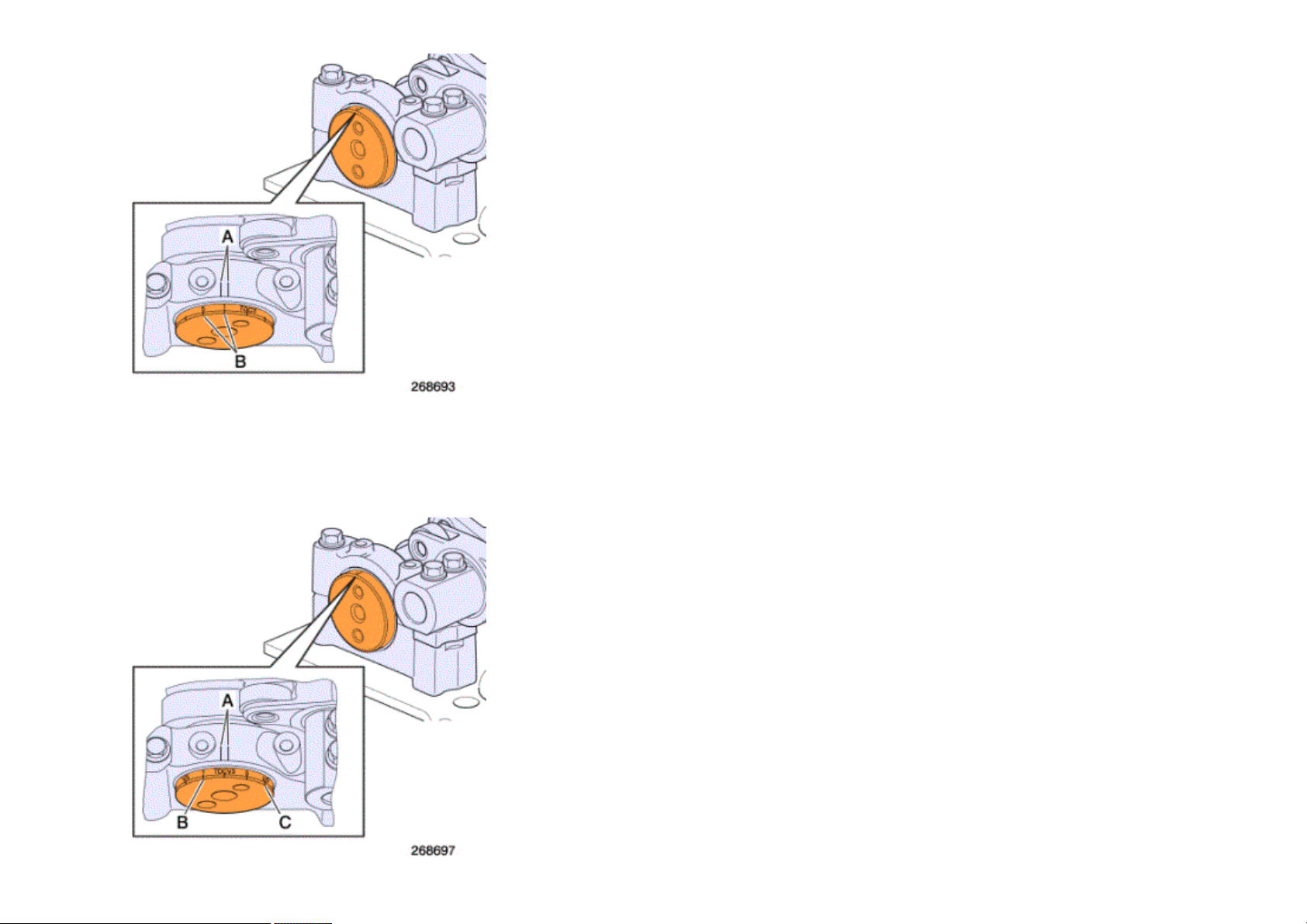
Without "Optibrake" exhaust brake
The marks (B) 1 - 5 - 3 - 6 - 2 - 4 correspond to the recommended inlet valve clearances , to the recommended exhaust valve clearances and to the
recommended pump injector pre-travel distances for each relative cylinder.
Mark (B) must be positioned in the centre of marks (A) when carrying out the adjustment.
Andrew Burrows Rocker arms / Adjustment 03/02/16
3 / 12
With "Optibrake" exhaust brake
The marks (B) 1 - 5 - 3 - 6 - 2 - 4 correspond to the recommended inlet valve clearances and to the recommended pump injector pre-travel distances for
each relative cylinder.
The marks (C) V1 - V5 - V3 - V6 - V2 - V4 correspond to the recommended exhaust valve clearances for each relative cylinder.
The marks (B) or (C) must be positioned between the marks (A) to make the correct adjustment.
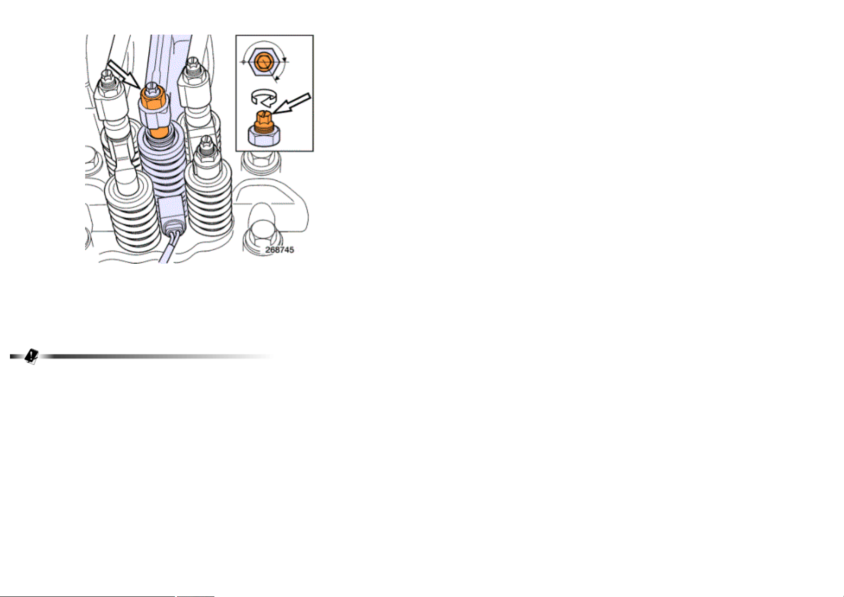
Adjustment of inlet valves
Measure the valve clearances using feeler gauges.
See pages .
Loosen the locknut and the adjuster.
Adjust the clearance between the rocker arm and the valve yoke by means of screw.
Tighten the locknut to torque while holding the adjuster.
See pages .
Make a mark on the rocker arm when adjustment is finished.
Perform the same operation on all the other cylinders.
Andrew Burrows Rocker arms / Adjustment 03/02/16
4 / 12
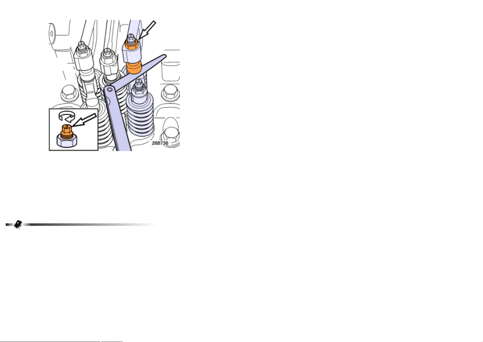
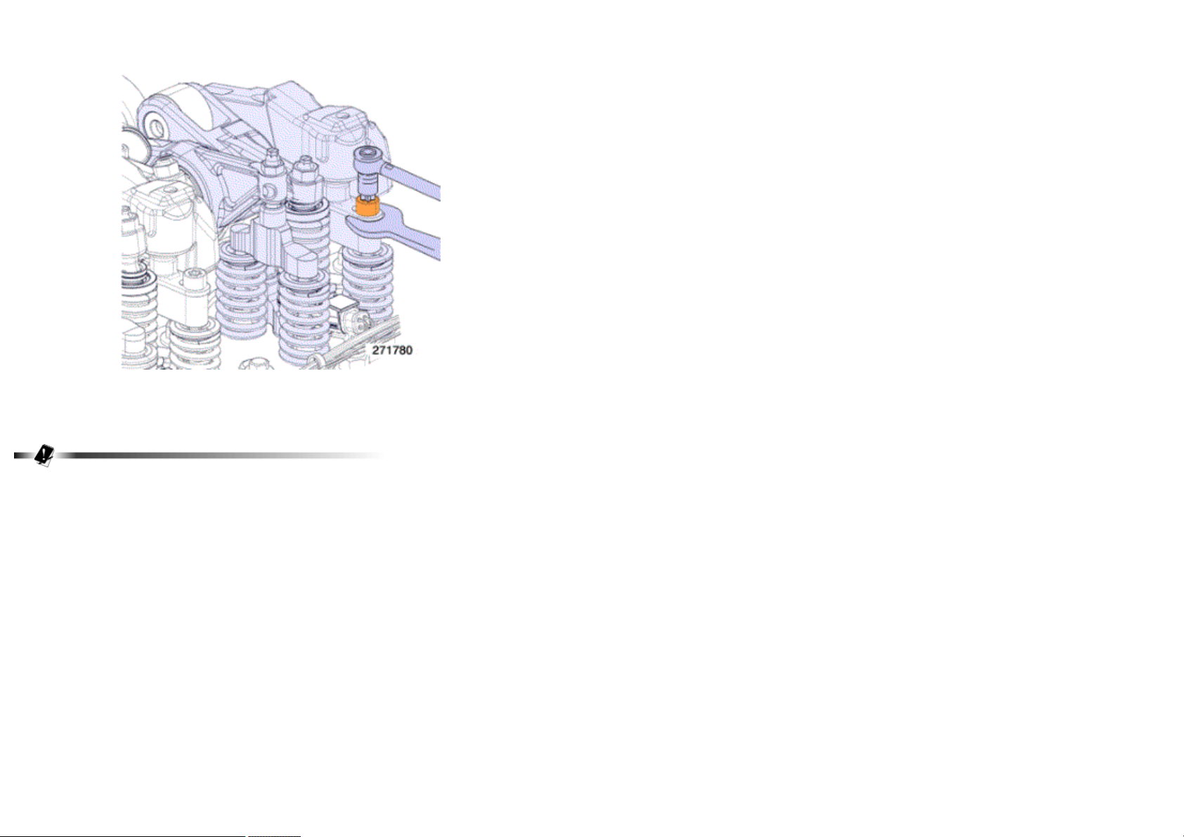
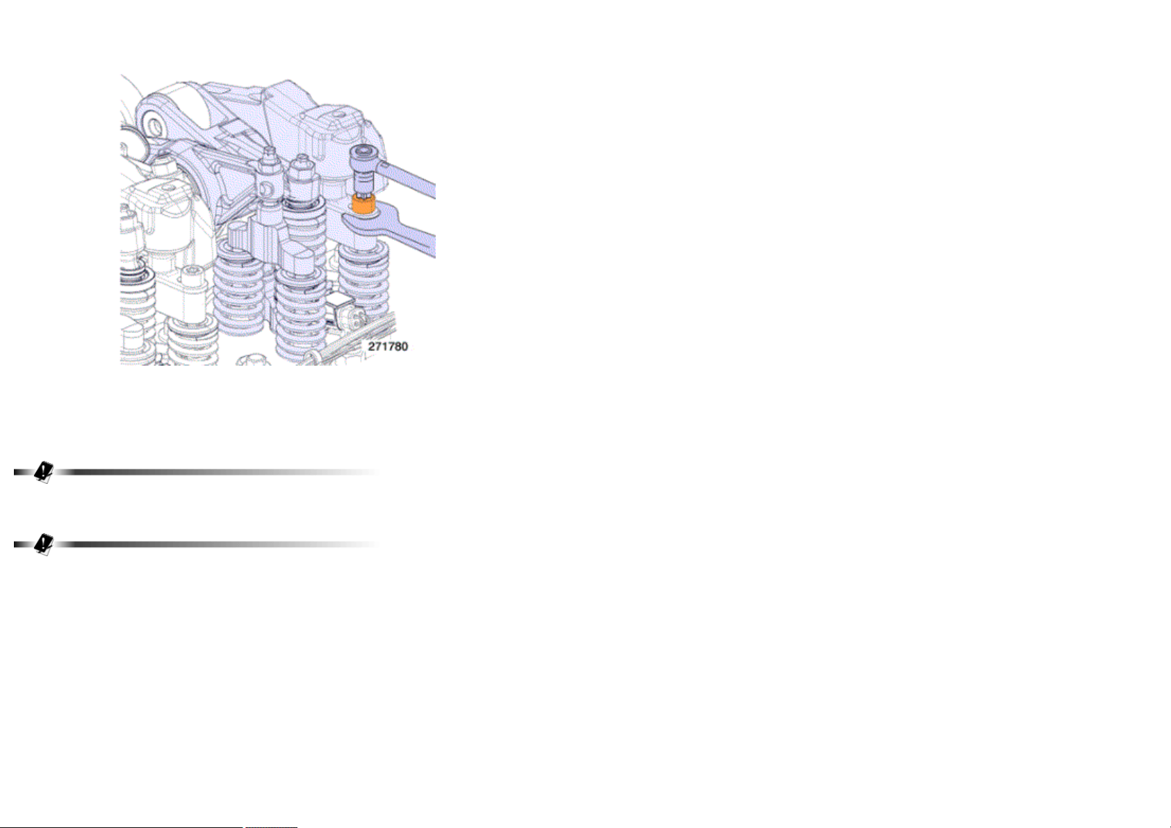
Adjustment of unit pump injectors pre-travel
Check the torque of the injector flange attachment bolts without removing the rocker arm assembly.
Use tool A.
A = 0162
Tighten to torque.
See pages .
This operation is to be performed at each valve adjustment maintenance.
Andrew Burrows Rocker arms / Adjustment 03/02/16
5 / 12
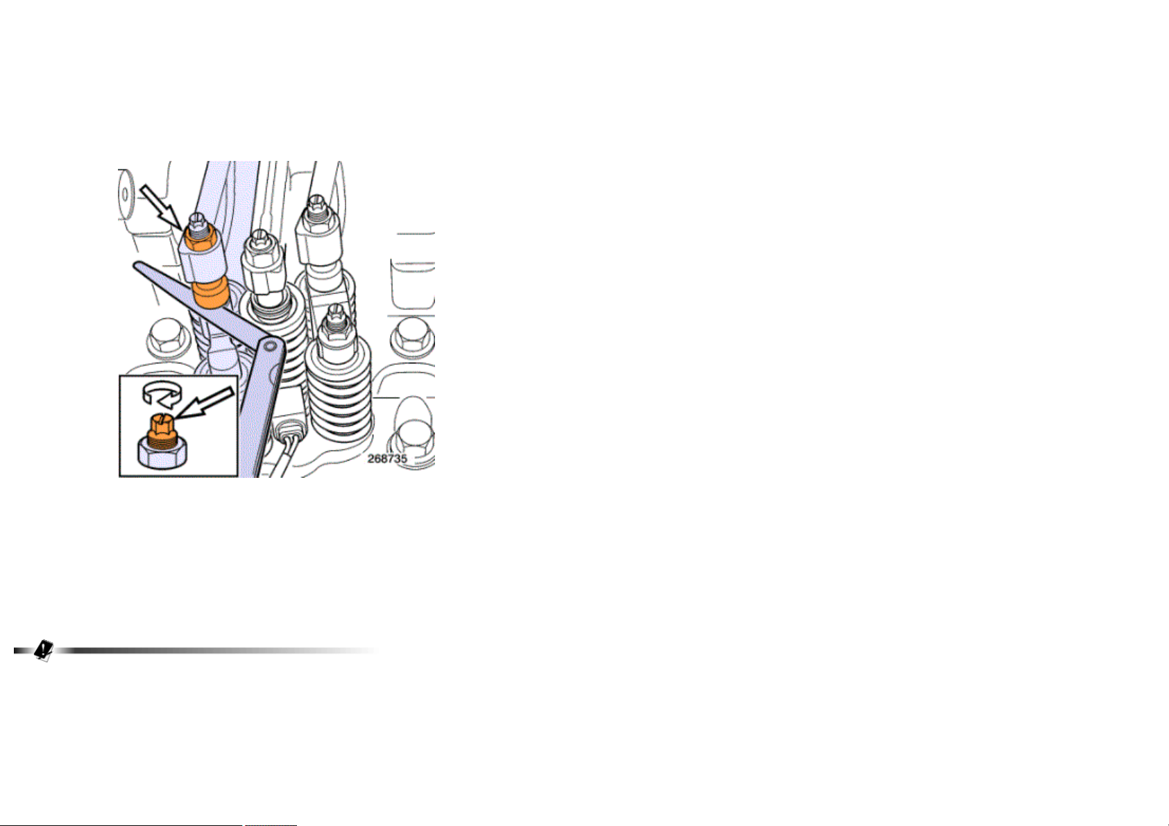
Loosen the locknut and the adjuster.
Screw up the adjuster by hand until contact is made with the pump injector.
Tighten the adjuster through 2/3 of a turn to obtain a unit pump injector preload.
Tighten the locknut to torque while holding the adjuster.
See pages .
Make a mark on the rocker arm when adjustment is finished.
Perform the same operation on all the other cylinders.
Exhaust valve adjustment
Andrew Burrows Rocker arms / Adjustment 03/02/16
6 / 12
Without "Optibrake" exhaust brake
Measure the valve clearances using feeler gauges.
See pages .
Loosen the locknut and the adjuster.
Adjust the clearance between the rocker arm and the valve yoke by means of screw.
Tighten the locknut to torque while holding the adjuster.
See pages .
Make a mark on the rocker arm when adjustment is finished.
Perform the same operation on all the other cylinders.
Andrew Burrows Rocker arms / Adjustment 03/02/16
7 / 12
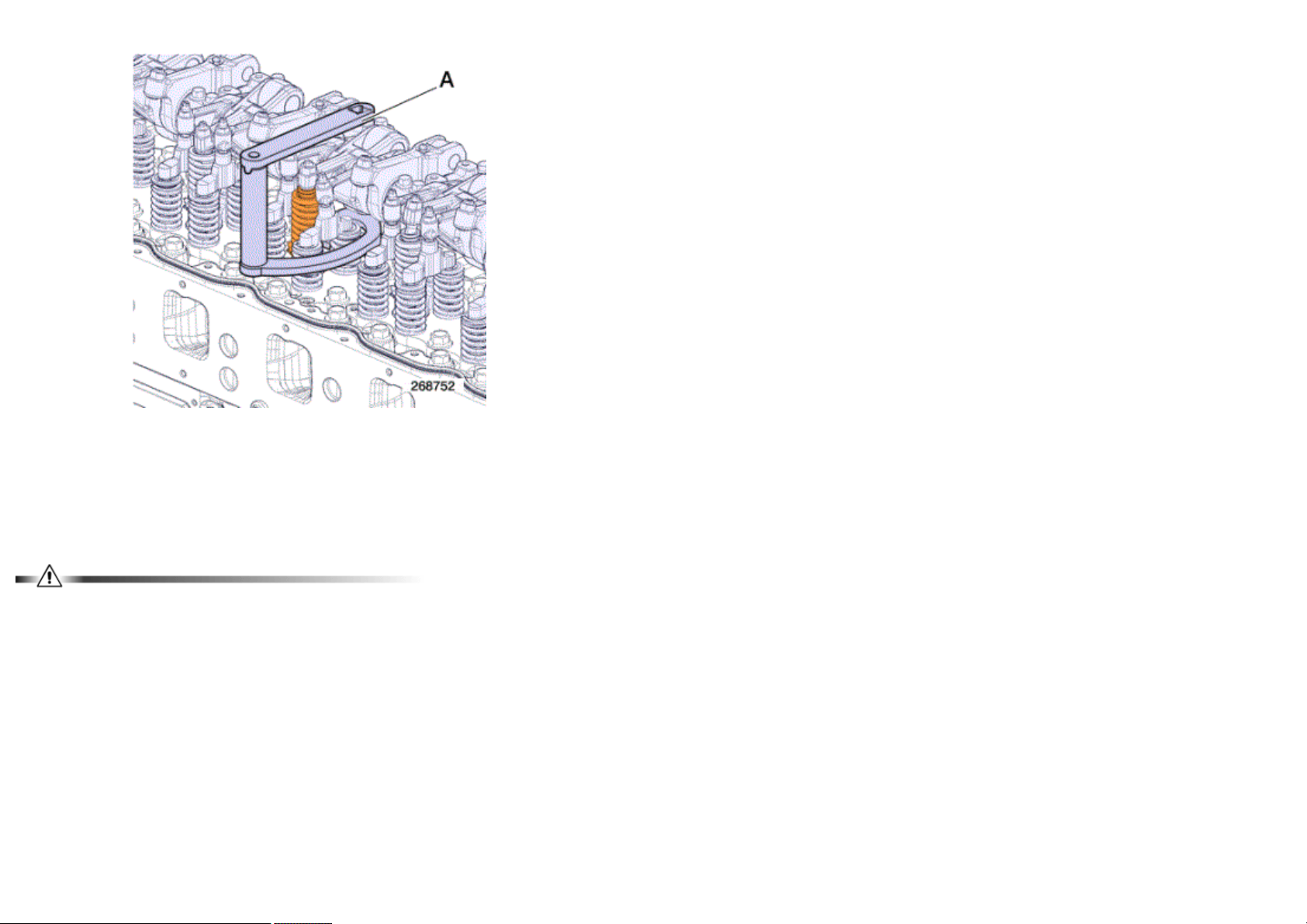
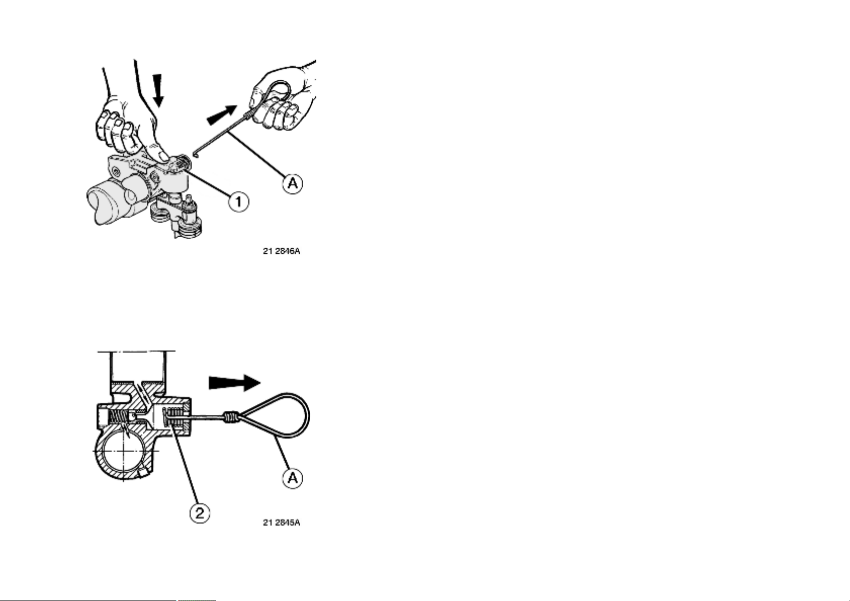
With "Optibrake" exhaust brake
Before making the adjustment, press rocker arm (1).
Compress valve spring (2) to free the oil in the rocker arm.
Use a piece of rigid iron wire to make a hook (A).
Andrew Burrows Rocker arms / Adjustment 03/02/16
8 / 12
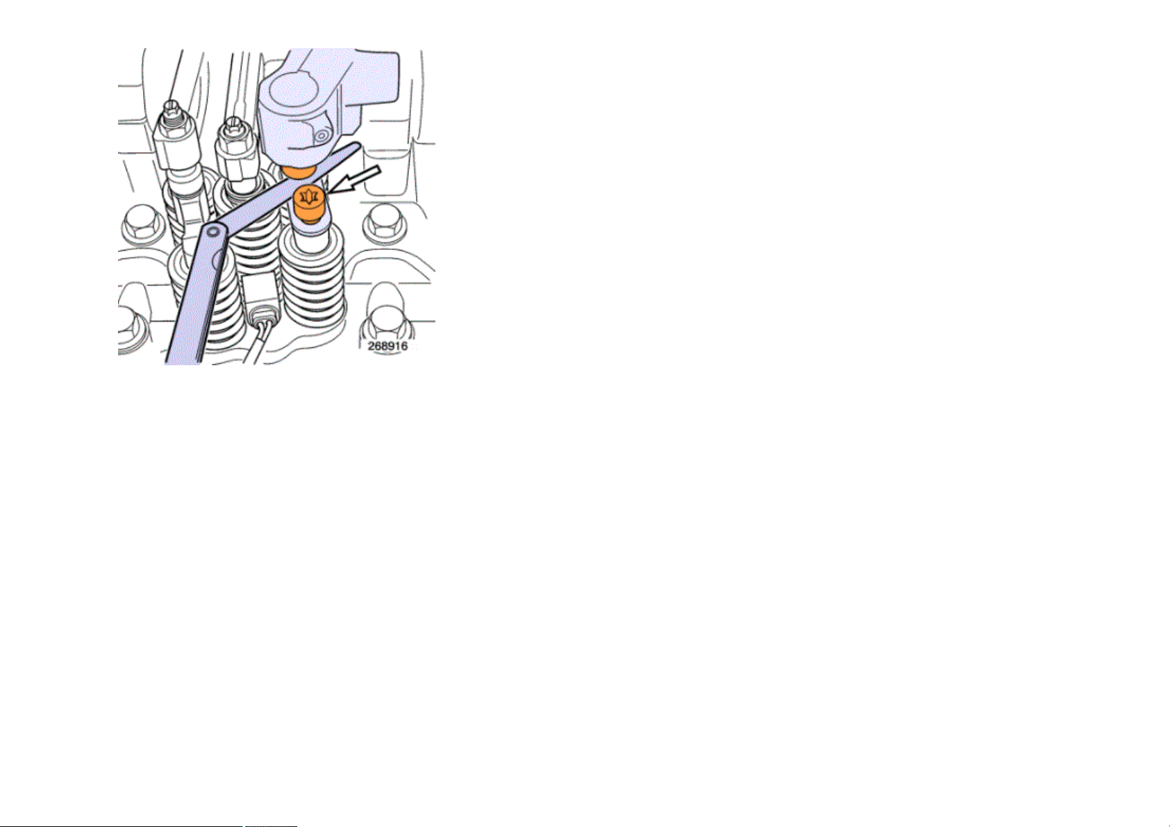
Check the clearance between the valve yoke and the exhaust rocker arm piston. Turn the piston to ensure that it is properly seated in its housing.
Use a feeler gauge corresponding to the recommended clearance.
See pages .
In the event of rocker arm play or sticking, make the check with a thicker or thinner feeler gauge in order to determine the thickness of the new adjusting
shim.
Andrew Burrows Rocker arms / Adjustment 03/02/16
9 / 12
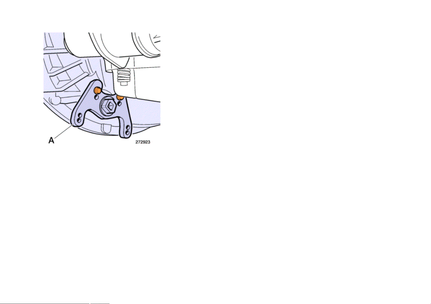
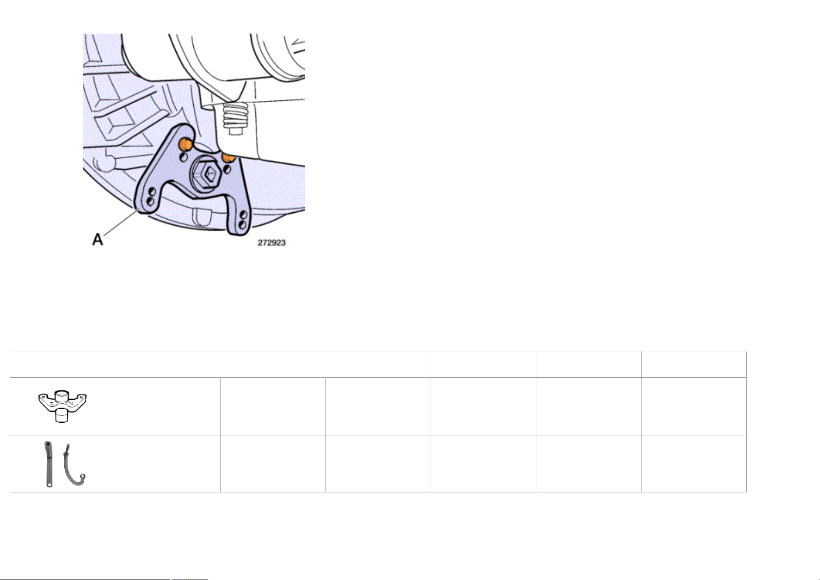
In the event of incorrect clearances.
Remove bolt.
Remove adjusting shim .
Hold the caliper in place when unbolting.
Andrew Burrows Rocker arms / Adjustment 03/02/16
10 / 12
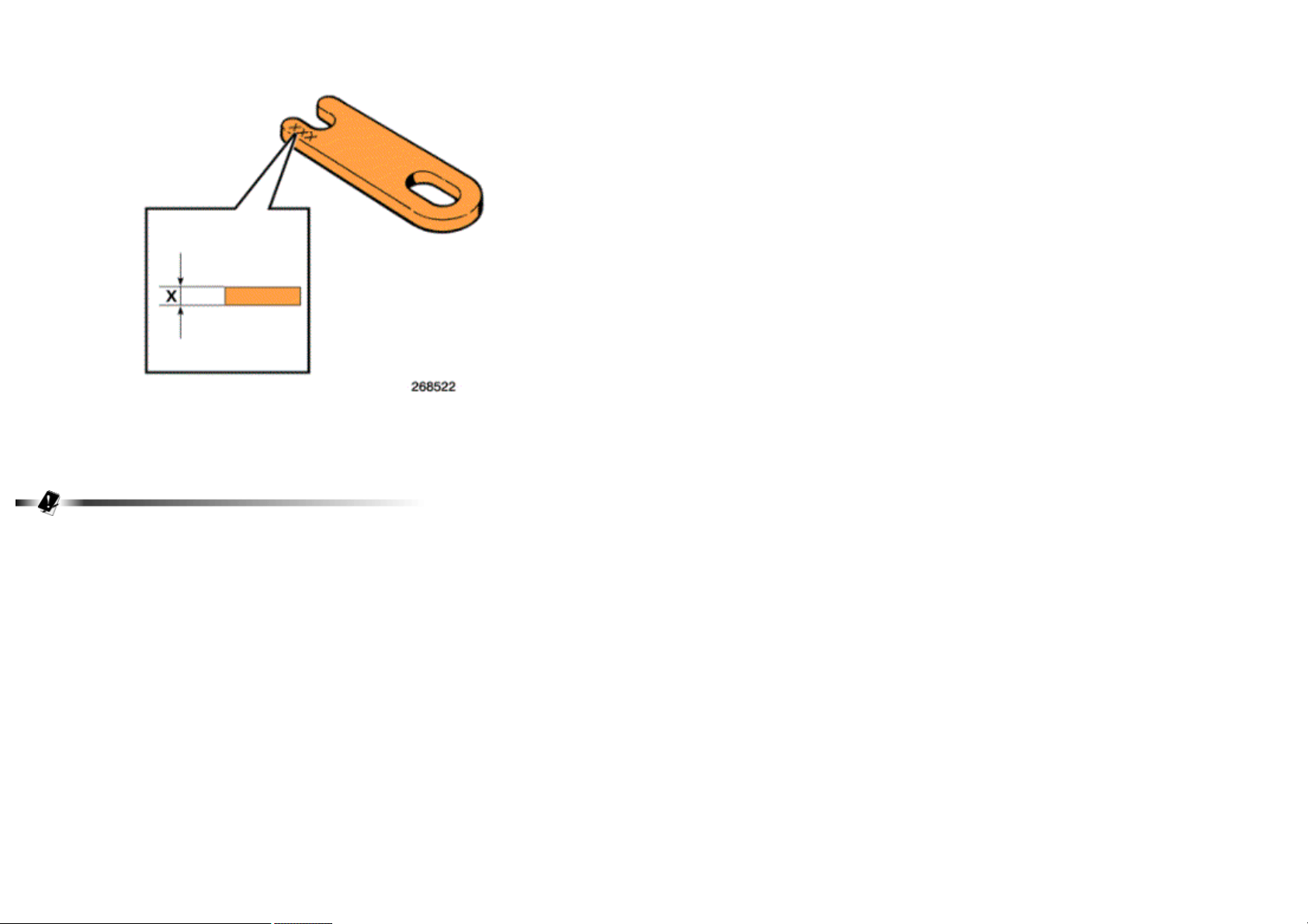
Note down the thickness X engraved on adjusting shim.
Determine the thickness of the new adjustment shim, in order to obtain the recommended clearance.
See pages .
You can superimpose a maximum of 2 adjusting shims, provided that they have the same thickness. Adjusting shims are available with thicknesses of
0.05 by0.05 mm.
Andrew Burrows Rocker arms / Adjustment 03/02/16
11 / 12
Fit shim.
Fit bolt.
Tighten to torque.
See pages .
Hold the caliper in place when tightening.
Again check the clearance between the valve yoke and the arm piston.
Make a mark on the rocker arm when adjustment is finished.
Perform the same operation on all the other cylinders.
Andrew Burrows Rocker arms / Adjustment 03/02/16
12 / 12
Remove tool A.
A = 6956
Tools
Specific tools
Illustration RENAULT
TRUCKS part N°
Designation Manufacturer's
reference N°
Manufacturer's code N° Scale Qty
7409996956 CONTROL 1 1
7488840162 WRENCH 2 1

Andrew Burrows Key / Diagram 02/02/16
1 / 7
Group 0 - Electronics
Polarity N° Designation
0010 Communication bus J1587-1 (+ signal)
0011 Communication bus J1587-1 (- signal)
0012 Communication bus J1939-1 (+ signal)
0013 Communication bus J1939-1 (- signal)
0014 Not assigned
0015 Radio remote control
0016 Radio remote control
0017 Radio remote control
0018 Radio remote control
0019 Radio remote control
0020 Radio remote control
0021 “ZF” communication bus (+ signal)
0022 “ZF” communication bus (- signal)
0023 Power supply relay control by vehicle management ECU
0024 Injection pump and camshaft speed sensor information (electronic injection / - signal)
0025 Injection pump and camshaft speed sensor information (electronic injection / + signal)
0026 Gear lever communication bus (+ signal)
0027 Hydraulic retarder proportional solenoid valve control
0029 Hydraulic retarder oil boosting solenoid valve control
0031 Hydraulic retarder coolant temperature information
0032 Hydraulic retarder coolant temperature information
0038 Retarder manual control (analogue signal)
0039 Alarm siren activation and/or disabling encoded line
0045 Communication bus for EBS trailer socket (+ signal)
0046 Communication bus for EBS trailer socket (- signal)
0056 Vehicle speed sensor encrypted data line
0057 Information display pull-down menu sequence change signal
0058 Information display pull-down menu sequence change signal
0061 Gearbox input shaft speed information (+ signal)
0062 Gearbox input shaft speed information (- signal)
0063 Automatic gearbox casing oil level sensor power supply
0064 Automatic gearbox identification line

Andrew Burrows Key / Diagram 02/02/16
2 / 7
0065 Automatic gearbox casing oil temperature sensor information
0066 Automatic gearbox casing oil level sensor information
0067 Communication bus J1587 for gearbox diagnostic socket (+ signal)
0068 Communication bus J1587 for gearbox diagnostic socket (- signal)
0069 Gearbox speed selector data bit 1
007 Accelerator pedal potentiometer power supply
0070 Gearbox speed selector data bit 2
0071 Gearbox speed selector data bit 4
0072 Gearbox speed selector data bit 8
0073 Gearbox speed selector data parity bit
0074 Link between gearbox ECU and gear lever display
0075 Automatic gearbox gear lever information in input mode on gearbox ECU
0076 Automatic gearbox hydraulic pressure sensor information
0084 Automatic gearbox output speed sensor information (- signal)
0086 Automatic gearbox temperature sensor information
0087 Automatic gearbox turbine speed sensor information
0088 Automatic gearbox output speed sensor information (+ signal)
0089 Retarder coolant temperature sensor information
0100 Onboard management data transmission bus (+ signal)
0101 Onboard management data transmission bus (- signal)
0102 Onboard management data reception bus (+ signal)
0103 Onboard management data reception bus (- signal)
0104 Communication bus J1587-2 (+ signal)
0105 Communication bus J1587-2 (- signal)
0107 RH front brake pads wear analogue sensor earth
0108 RH front brake pads wear analogue sensor information
0109 RH front brake pads wear analogue sensor power supply (+5V)
011 Humidity sensor information
0114 Temperature sensor analogue signal for adjusting exhaust gases (EGR)
0116 Coolant temperature sensor analogue signal
0117 Pusher or follower rear axle angle sensor minimum voltage
0118 Pusher or follower rear axle angle sensor maximum voltage
0119 Front axle angle sensor minimum voltage
0120 Front axle angle sensor minimum voltage
0123 Red LED indicating that vehicle alarm is set (+) power supply

Andrew Burrows Key / Diagram 02/02/16
3 / 7
0127 Alarm ultrasonic reception (RX+ signal)
0128 Alarm ultrasonic reception (RX- signal)
0129 Alarm ultrasonic transmission (RX+ signal)
0130 Alarm ultrasonic transmission (RX- signal)
0143 Engine crankcase pressure sensor information
0144 Fuel pressure sensor information
0145 Available power supply (earth delivered by ECU for on-chassis engine stop control)
0146 Available power supply (Information requested by for on-chassis engine stop control)
0147 Communication bus between EBS ECU and front module (- signal)
0148 Communication bus between EBS ECU and front module (+ signal)
0149 Communication bus between EBS ECU and first additional module (- signal)
0150 Communication bus between EBS ECU and first additional module (- signal)
0151 Engine coolant level sensor information
0160 LH front brake pads wear analogue sensor earth
0161 LH front brake pads wear analogue sensor information
0162 LH front brake pads wear analogue sensor power supply (+5V)
0163 First axle RH rear brake pads wear analogue sensor earth
0164 First axle RH rear brake pads wear analogue sensor information
0165 First axle RH rear brake pads wear analogue sensor power supply (+5V)
0166 First axle LH rear brake pads wear analogue sensor earth
0167 First axle LH rear brake pads wear analogue sensor information
0168 First axle LH rear brake pads wear analogue sensor power supply (+5V)
0169 Second axle RH rear brake pads wear analogue sensor earth
017 Accelerator pedal position potentiometer information
0170 Second axle RH rear brake pads wear analogue sensor information
0171 Second axle LH rear brake pads wear analogue sensor power supply (+5V)
0172 Second axle LH rear brake pads wear analogue sensor earth
0173 Second axle LH rear brake pads wear analogue sensor information
0174 Second axle LH rear brake pads wear analogue sensor power supply (+5V)
0175 First rear axle RH speed sensor information
0176 First rear axle RH speed sensor information
0177 First rear axle LH speed sensor information
0178 First rear axle LH speed sensor information
0180 RH rear brake pads wear analogue sensor earth on PUSHER additional module
0181 RH rear brake pads wear analogue sensor information on PUSHER additional module

Andrew Burrows Key / Diagram 02/02/16
4 / 7
0182 RH rear brake pads wear analogue sensor power supply (+5V) on PUSHER additional module
0183 LH rear brake pads wear analogue sensor earth on PUSHER additional module
0184 LH rear brake pads wear analogue sensor information on PUSHER additional module
0185 LH rear brake pads wear analogue sensor power supply (+5V) on PUSHER additional module
0186 LH rear brake pads wear analogue sensor earth on PUSHER additional module
0187 RH rear brake pads wear sensor information (follower axle module)
0188 RH rear brake pads wear sensor power supply (+5V) (follower axle module)
0189 LH brake pads wear sensor earth (follower axle module)
0190 LH brake pads wear sensor information (follower axle module)
0191 LH brake pads wear sensor power supply (+5V) (follower axle module)
0192 “Driver’s side hand presence” door sensor information (+ signal)
0193 “Driver’s side hand presence” door sensor power supply
0194 “Driver’s side hand presence” door sensor information (- signal)
0195 “Driver’s side hand presence” door sensor information (+ signal)
0196 “Passenger’s side hand presence” door sensor power supply
0197 “Passenger’s side hand presence” door sensor information (- signal)
0198 Driver’s side door antenna (+ signal)
0199 Driver’s side door antenna (- signal)
0200 Passenger’s side door antenna (+ signal)
0201 Passenger’s side door antenna (- signal)
0202 Cab antenna 1 (+ signal)
0203 Cab antenna 1 (- signal)
0204 Cab antenna 2 (+ signal)
0205 Cab antenna 2 (- signal)
0206 Communication bus J1939-6 (+ signal)
0207 Communication bus J1939-6 (- signal)
0208 Communication bus J1587 (+ signal)
0209 Communication bus J1587 (- signal)
0212 Cruise control analogue sensor power supply
022 Accelerator pedal position potentiometer information
028 Cruise control ON/OFF control
029 Cruise control ON/OFF control
03 Rear stop lights power supply (12N socket)
030 RH rear direction indicator light power supply (12N socket)
0307 Rear fog lights power supply (12N socket)

Andrew Burrows Key / Diagram 02/02/16
5 / 7
0308 LH rear direction indicator light power supply (12N socket)
031 Cruise control signal
032 Engine oil temperature information with electronic fuel-injection system
033 Intake air temperature information with electronic fuel-injection system
034 Intake air temperature information (P2) with electronic fuel-injection system
0374 Encoded link between radio frequency receiver and alarm
0375 Hazard lights control by radio frequency receiver and/or alarm
0376 EBS module pressure sensor power supply for trailer control
0377 EBS module pressure sensor information for trailer control
0380 EBS module pressure sensor earth for trailer control
0381 Communication bus between EBS ECU and second additional module (- signal)
0382 Communication bus between EBS ECU and second additional module (+ signal)
0384 "PTO" control signal input for engine speed control (customer’s pre-arrangement)
039 Brake pedal position sensor information with EBS system
040 Brake pedal position sensor information with EBS system
0403 Encoded tractor/trailer link between alarm and freight protection module
0405 Tachograph serial data bus for fleet management
041 Line K information for diagnostic socket
0411 Communication bus J1939-2 (+ signal)
0412 Communication bus J1939-2 (- signal)
0413 Communication bus for bodybuilding or fleet management (- signal)
0414 Communication bus for bodybuilding or fleet management (+ signal)
0415 Communication bus between EBS ECU and on-chassis acceleration sensor (+ signal)
0416 Communication bus between EBS ECU and on-chassis acceleration sensor (- signal)
0424 Communication bus J1939 for docking radar (+ signal)
0425 Communication bus J1939 for docking radar (- signal)
045 Cruise control deceleration control
0460 Switch-operated control (bodybuilder’s pre-arrangement)
0461 Switch-operated control (bodybuilder’s pre-arrangement)
0462 Communication bus for vehicle OBD data socket (+ signal)
0463 Communication bus for vehicle OBD data socket (- signal)
0464 Diesel fuel particulate filter temperature sensor power supply
0465 Diesel fuel particulate filter temperature sensor power supply
047 Cruise control acceleration control
052 Flywheel engine speed sensor information (+ signal)

Andrew Burrows Key / Diagram 02/02/16
6 / 7
055 Flywheel engine speed sensor information (- signal)
056 Brake pedal position sensor power supply (+5V)
057 EBS system load sensor information
0608 Reversing lights power supply (12N socket)
0632 Rear marker lights power supply (12N socket)
064 Communication bus between EBS ECU and double rear module (- signal)
066 Communication bus between EBS ECU and double rear module (+ signal)
071 EBS system load sensor earth
072 EBS ECU earth for brake valve
073 EBS system load sensor power supply (+5V)
077 Accelerator pedal position sensor information (rest position)
079 Variable-drive fan power supply
080 Engine oil pressure sensor earth
081 Engine oil pressure sensor power supply
082 Communication bus between gear selector and automatic gearbox ECU (+ signal)
083 Communication bus between gear selector and automatic gearbox ECU (- signal)
084 Shunt between gearbox ECU terminal 66 and 26
0801 Communication bus J1587 for adaptive cruise control system (+ signal)
0802 Communication bus J1587 for adaptive cruise control system (- signal)
0803 Information from cruise control system
0804 Information from cruise control system
0805 Information from cruise control system
0806 Information from cruise control system
0807 Information from cruise control system
0808 Information from cruise control system
0809 Information from cruise control system
0810 Gearbox output speed information (+ signal)
0811 Gearbox output speed information (- signal)
0812 First front axle RH roadwheel speed sensor information (+ signal)
0813 First front axle RH roadwheel speed sensor information (- signal)
0814 Second front axle RH roadwheel speed sensor information (+ signal)
0815 Second front axle RH roadwheel speed sensor information (- signal)
0816 First front axle LH wheel speed sensor information (+ signal)
0817 First front axle LH wheel speed sensor information (- signal)
0818 Second front axle LH wheel speed sensor information (+ signal)

Andrew Burrows Key / Diagram 02/02/16
7 / 7
0819 Second front axle LH wheel speed sensor information (- signal)
0820 First front axle RH wheel speed sensor information (+ signal)
0821 First front axle RH wheel speed sensor information (- signal)
0822 First front axle LH wheel speed sensor information (+ signal)
0823 First front axle LH wheel speed sensor information (- signal)
0833 Inclination sensor power supply (+)
0834 Inclination sensor information
0835 Inclination sensor power supply (-)
0836 Clutch position sensor power supply (+)
0837 Clutch position sensor information
0838 Clutch position sensor power supply (-)
0839 Parking brake control power supply (-)
0840 Parking brake control potentiometers N° 1 & 2 power supply
0841 Parking brake wake-up contact power supply
0842 Parking brake control potentiometer N° 1 information
0843 Parking brake control potentiometer N° 2 information
0844 Parking brake unlocking switch N° 1 information
0845 Parking brake unlocking switch N° 2 information
0846 Parking brake module air pressure sensor power supply (+)
0847 Parking brake module air pressure sensor power supply (-)
0848 Parking brake module air pressure sensor information
085 Rail pressure sensor information
087 Engine oil pressure sensor information
088 Retarder torque sensor information

Andrew Burrows Key / Diagram 02/02/16
1 / 3
Group 1 - Earths and negative power supplies
Polarity N° Designation
1 Vehicle general earth
11 Microphone (- signal)
12 Gearbox neutral position sensor information
13 Engine water circuit by-pass solenoid valve control
14 AdBlue heating resistor control (in circuit from tank to pump module)
15 AdBlue heating resistor control (in circuit from pump module to dosing solenoid valve)
16 AdBlue heating resistor control (in circuit from dosing solenoid valve to pump module)
17 AdBlue heating resistor control (in circuit from pump module to tank)
18 12 Volts socket earth (multi-pass cab option)
19 AdBlue heating resistor control (in filter, on pump)
101 Humidity sensor power supply (-)
104 Two-tone horn power supply (-)
106 Assistance control information
119 "Front door open" position sensor information for lighting
(overhead light, stepwell light, locker lights, ambient lighting...)
123 Clutch pedal position sensor information
124 12 volts power socket earth
130 Overhead lights lighting earth (after master switch)
131 Communication bus between gear selector and ECU (- signal)
132 Communication bus between gear selector and ECU (+ signal)
141 Tachograph speed sensor information
142 Tachograph speed sensor information
144 Voltage converter earth for CB power supply
147 Master switch coil control
148 Master switch control
151 Available power supply (rear compartment open warning light)
152 Overhead lights earth
155 Voltage converter earth for radiotelephone power supply
156 Transfer box "low speed" information
157 Front wheels diff lock information
158 Transfer box PTO engaged information
159 Transfer box diff lock information

Andrew Burrows Key / Diagram 02/02/16
2 / 3
169 Doors central locking electronic box inhibition earth (presence of key in ignition switch)
173 N° 1/2/3 cylinder injectors earth (line 1)
174 N° 4/5/6 cylinder injectors earth (line 1)
183 Hydraulic retarder proportional solenoid valve earth
184 Hydraulic retarder charge accumulator solenoid valve earth
193 Earth between A/C ECU and fan management ECU
197 Master switch relay earth
198 Battery charging receptacle earth
1001 Front spotlight earth
1006 Exhaust brake solenoid valve N° 2 control earth
1007 Exhaust brake solenoid valve N° 2 control earth
1008 Exhaust brake electrovalve power supply (-)
1010 Fan electric clutch pilot-control earth
1012 EBS system solenoid valve earth
1018 Reversing lights relay control earth
1019 12 volts socket voltage converter earth
1020 Rear, doors opening/closing information
1021 Rear overhead lights power supply (-)
1025 Corrected vehicle speed information
1026 Engine speed regulation control (first selection)
1029 Automatic gearbox solenoid valve earth
1030 Automatic gearbox solenoid valve earth
1031 Automatic gearbox solenoid valve earth
1032 Automatic gearbox solenoid valve earth
1033 Automatic gearbox solenoid valve earth
1034 Automatic gearbox solenoid valve earth
1035 Automatic gearbox solenoid valve earth
1036 Automatic gearbox solenoid valve earth
1037 Automatic gearbox solenoid valve earth
1038 Automatic gearbox solenoid valve earth
1039 Automatic gearbox neutral earth
1043 Automatic gearbox solenoid valve earth
1045 Retarder control selector interface earth
1046 Automatic gearbox solenoid valve earth
1051 Air conditioning cut-out upon engine power loss control

Andrew Burrows Key / Diagram 02/02/16
3 / 3
1058 Fuel preheating relay control
1077 Earth delivered by engine management ECU for starting relay control
1081 Piloted axle control sensor earth
1084 Piloted axle control solenoid valve earth
1119 Alarm diode earth
1124 Roadwheels anti-slip sensor earth (ESP)
1140 PTO N° 1 engagement request
1141 Engine speed regulation control (second selection)
1147 Master switch closing control (ADR)
1148 Master switch closing control (ADR)
1149 Master switch warning light earth (ADR)
1150 Alternator earthing relay (-) control (ADR)
1151 N° 1/2/3 cylinder injectors earth (line 2)
1152 Cruise control operating control
1153 N° 4/5/6 cylinder injectors earth (line 2)
1154 Fuel pump control
1155 Air suspension ECU relay control
1156 Water/fuel separator bleeding solenoid valve control
1157 Alarm sound volume reduction control
1159 "Door open" information
1160 Engine retarder VGT2 solenoid valve earth
1161 Information feedback for "difficult terrain" warning light
1162 Turbocharger speed sensor earth
1163 Master switch diode earthing (ADR)
1164 Electrical master switch relay earthing (ADR)
1165 Single "H" solenoid valve N° 1 earthing
1166 Single "H" solenoid valve N° 2 earthing
1167 AdBlue tank level and temperature sensor earth
1168 AdBlue tank level and temperature sensor power supply (+5V)
1180 Driver presence in seat sensor power supply (-)
1200 Gearbox neutral position sensor information (after diode)

Andrew Burrows Key / Diagram 02/02/16
1 / 4
Group 2 - Positive power supplies
Polarity N° Designation
2 (+) power supply capable of being cut by master switch
20 Microphone (+ signal)
21 Urea heating resistor N° 1 (+) power supply
22 Key switch relay excitation (after ignition position)
23 Urea heating resistor N° 2 (+) power supply
24 (+) power supply after ignition (air management ECU, information
display, alarm, engine immobilizer, doors central locking)
25 Battery charge, alternator terminal A+, engine running warning light
26 Charging socket (+) power supply
28 Hydraulic pump power supply
200 Radio antenna power supply (+12V)
201 (+) power supply not cut by master switch
202 Full-time (+) power supply (headlights and hazard lights management ECU)
203 (+) power supply not cut by master switch (tachograph)
205 Starter relay control
206 (+) power supply after relay (fan-coil heaters)
208 (+) power supply capable of being cut by master switch (available power supply)
209 Radio antenna coaxial cable signal
210 Radio antenna coaxial cable earth
211 (+) power supply after ignition (ABS/EBS trailer socket)
212 (+) power supply after vehicle management ECU power supply relay
214 Accessories (+) power supply (ignition key position 1)
215 (+) power supply after ignition (rearview mirror
defrosting relay, swivelling rearview mirrors control)
216 GPS antenna coaxial cable signal
217 GPS antenna coaxial cable earth
218 GSM antenna coaxial cable signal
219 GSM antenna coaxial cable earth
220 GSM antenna coaxial cable signal (radiotelephone pre-arrangement)
221 GSM antenna coaxial cable earth (radiotelephone pre-arrangement)
229 (+) power supply after ignition (vehicle management ECU, tachograph)
238 (+) power supply after master switch (heated windscreen)
240 Brake pedal position sensor information

Andrew Burrows Key / Diagram 02/02/16
2 / 4
243 (+) power supply after ignition (cab tilt relay)
247 (+) power supply capable of being cut by master switch (cab tilting)
260 (+) power supply after air suspension ECU power supply relay
263 Full-time (+) power supply for central locking of electrical locks and electrical master switch
control or network isolation relay power supply and electronic master switch if FPT type vehicle
268 Intermediate conductor between battery banks
270 (+) power supply capable of being cut by master switch (automatic gearbox)
273 (+) power supply after ignition (hydraulic retarder)
274 (+) power supply after ignition (air suspension management ECU)
275 (+) power supply after ignition (available power supply)
291 Engine management and vehicle management ECUs
electronic fuel-injection function power supply
292 Engine ECU electronic fuel-injection function digital power supply
293 N° 1 cylinder injector control (line 1)
294 N° 3 cylinder injector control (line 1)
295 N° 2 cylinder injector control (line 1)
296 N° 5 cylinder injector control (line 1)
297 N° 6 cylinder injector control (line 1)
298 N° 4 cylinder injector control (line 1)
2000 (+) power supply after heated windscreen resistor fuse
2005 Brake pedal position sensor information
2014 (+) power supply after ignition (air conditioning/heating)
2016 Information between air conditioning control and ventilation control ECU.
2017 Information between air conditioning control and ventilation control ECU.
2018 Information between air conditioning control and ventilation control ECU.
2023 (+) power supply after master switch for retarder
2025 (+) power supply after ignition for ABS and/or EBS system
2050 Auto/manual retarder mode request
2056 (+) power supply capable of being cut by master switch
2057 on-chassis (+) power supply (bodybuilder’s pre-arrangement)
2069 Automatic gearbox solenoid valve (+) power supply
2070 Automatic gearbox solenoid valve (+) power supply
2071 Automatic gearbox solenoid valve (+) power supply
2072 Automatic gearbox solenoid valve (+) power supply
2088 Automatic gearbox solenoid valve (+) power supply
2093 Power supply after master switch

Andrew Burrows Key / Diagram 02/02/16
3 / 4
2109 Air suspension ECU remote control electrical socket (+) power supply
2117 (+) power supply after ignition
2119 Master switch opening condition (ADR)
2120 (+) power supply after master switch (available power supply)
2121 (+) power supply after ignition (diff lock control, PTO electrovalves)
2122 (+) power supply after ignition (vehicle management ECU)
2123 (+) power supply after ignition (engine speed regulation adjustment,
water/fuel separator bleed solenoid valve, auto/manual selection)
2124 Accelerator and clutch pedals position sensor power supply
2125 (+) power supply after bodybuilder’s pre-arrangements ECU relay
2126 Alternator earthing relay (+) power supply (ADR)
2127 (+) power supply after automatic gearbox ECU relay
2128 Night lighting power supply (available power supply)
2132 Batteries DC (+) power supply (independent heating)
2220 Winch power supply
2221 (+) power supply after master switch (available for bodybuilding and/or parking socket)
2222 (+) power supply for all power fuses (alternator output B+)
2223 (+) power supply before master switch (flasher unit and power fuses box)
2224 (+) power supply after master switch (air preheating)
2226 Alternator excitation earthing upon opening of master switch
2227 (+) power supply before master switch (engine
immobilizer electronic box, automatic gearbox ECUs)
2229 Alternator-controlled (+) power supply (engine running)
2230 (+) power supply after master switch (air production management ECU)
2231 Accessories (+) power supply (sun-roof and headlamps ride corrector)
2232 Accessories (+) power supply (electrically-operated windows)
2233 (+) power supply after master switch
2234 (+) power supply after ignition (in-cab bodybuilder’s pre-arrangements)
2235 Vehicle management ECU “wake-up” (+) power supply
2302 (+) power supply after master switch (refrigerator and voltage dropper)
2303 Alarm siren and piloted axle ECU power supply
2304 (+) power supply after master switch (independent heating)
2306 (+) power supply after master switch (independent heating)
2307 "Batteries being charged" information (engine running)
2309 (+) power supply after master switch (EBS electronic box ECU)
2310 (+) power supply after ignition (onboard management ECU and doors management ECU)

Andrew Burrows Key / Diagram 02/02/16
4 / 4
2311 (+) power supply after ignition (available power supply)
2312 (+) power supply after ignition (onboard management ECU)
2315 Accessories power supply (bodybuilder’s pre-arrangement)
2316 (+) power supply after master switch (lighting and signalling management ECU)
2317 (+) power supply after ignition (reversing lights and bodybuilder’s pre-arrangements relay)
2318 "Panic / alarm" system control
2319 Alarm sound volume reduction information
2320 Automatic gearbox ECU power supply relay control
2323 Engine coolant fan motor power supply
2325 Power supply after ignition (gear selector)
2327 (+) power supply after master switch (onboard management system)
2328 Batteries DC power supply
2328 Alimentation (+) directe batterie après interrupteur général de l'équiment ADR
2329 (+) power supply vehicle management ECU relay
2330 Jake brake relay power supply
2331 24 Volts dashboard socket and 24V/12V voltage converter power supply
2332 Air conditioning electronic management power supply
2334 Driver presence in seat sensor power supply power supply (+)
2930 N° 1 cylinder injector control (line 2)
2940 N° 3 cylinder injector control (line 2)
2950 N° 2 cylinder injector control (line 2)
2960 N° 5 cylinder injector control (line 2)
2970 N° 6 cylinder injector control (line 2)
2980 N° 4 cylinder injector control (line 2)
2981 Optiroll mode request

Andrew Burrows Key / Diagram 02/02/16
1 / 2
Group 3 - Signalling
Polarity N° Designation
3 Stop lights power supply
30 Trailer RH side direction change indicator lights power supply
31 Hazard lights control
32 Vehicle RH side direction change indicator lights control
33 Vehicle LH side direction change indicator lights control
34 Day/night function tell-tale light power supply
36 Hazard lights warning light control
37 RH front direction change indicator lights and side repeaters power supply
38 RH rear direction change indicator lights power supply
39 LH front direction change indicator lights and side repeaters power supply
301 LH rear direction change indicator lights power supply
302 LH front direction change indicator lights and side repeaters power supply
303 Parking lights lighting relay control
304 RH side parking lights and marker lights power supply
305 LH side parking lights and marker lights power supply
306 (+) power supply before rear fog lights fuse
307 Rear fog lights power supply
310 (+) power supply after master switch (horn)
311 Horn power supply
312 Horn relay control
313 Parking lights lighting control
320 Day/night function relay control
321 (+) power supply after master switch (illuminated warning)
322 Illuminated warning relay control (revolving beacons, illuminated "D" signs...)
323 Illuminated warning power supply
352 Trailer EBS system state of activation information
370 Rear fog lights lighting relay control
373 (+) power supply after master switch (steering wheel
fingertip controls – main beam headlights lighting)
374 Encoded line between alarm ECU and doors central locking ECU
386 “Heated rearview mirrors" function activation request
388 12 Volts power supply coming from voltage converter for headlamps ride correctors

Andrew Burrows Key / Diagram 02/02/16
2 / 2
389 Penetration lights pre-arrangement and front grille identification lights power supply
390 Two-tone horn power supply

Andrew Burrows Key / Diagram 02/02/16
1 / 4
Group 4 - Comfort accessories
Polarity N° Designation
4 Heated rearview mirrors resistors and windscreen defrosting controls power supply
41 12V power supply for 12 Volts socket (multi-pass cab option)
43 Air conditioning fan power supply relay control
45 (+) power supply after master switch (overhead lights)
46 12V power supply after 24V/12V converter for radiotelephone
47 Accessories power supply (headlamps ride correctors motor)
402 Driver’s side window winder motor power supply
403 Driver’s side window winder motor power supply
404 Auxiliary audio input, LH side
405 Auxiliary audio input, RH side
406 Auxiliary audio inputs earth
407 Auxiliary audio inputs diagnostic line
413 Independent heating fuel pump motor (-) power supply
414 Independent heating fuel pump motor (+) power supply
428 Swivelling rearview mirrors motors (-) power supply
429 Swivelling rearview mirrors motors (+) power supply
430 RH swivelling rearview mirror vertical movement motor (+) power supply
431 LH swivelling rearview mirror horizontal movement (+) power supply
432 RH swivelling rearview mirror horizontal movement (+) power supply
433 Passenger’s side electrically-operated front curtains motor control
434 Link between passenger’s side switch and driver’s side curtains control switch
435 Link between passenger’s side switch and driver’s side curtains control switch
436 Switch-operated order for locking electric door strikers
437 Headlamps ride adjustment
443 Passenger’s side electrically-operated front curtains motor control
444 LH front loudspeaker earth
445 Rear loudspeaker power supply (+), RH side
446 Rear loudspeaker power supply (-), RH side
447 LH front loudspeaker power supply
448 RH front loudspeaker power supply
449 Rear loudspeaker power supply (+), LH side
450 Rear loudspeaker power supply (-), LH side

Andrew Burrows Key / Diagram 02/02/16
2 / 4
451 LH front loudspeaker power supply
452 (+) power supply after master switch (diagnostic and data extraction sockets)
454 Windscreen electrically-operated curtains motor control
455 Windscreen electrically-operated curtains motor control
456 Accessories power supply (electrically-operated curtains)
462 Power supply after air conditioning compressor "pressure sensor" block fuse
463 (+) power supply after air conditioning compressor "pressure sensor"
block fuse (hydraulic retarder, automatic gearbox, horn, fan-coil heater)
469 Link between passenger’s side and driver’s side window winder motor control switch
470 Link between passenger’s side and driver’s side window winder motor control switch
476 Independent heating control
484 Switch-controlled doors electric strikers unlocking order
485 Cab tilt pump motor power supply
489 Fan-coil heater pressure sensor power supply
491 Air/water independent heater water distribution solenoid valve control
496 Passenger’s side front window winder motor power supply
497 Passenger’s side front window winder motor power supply
4000 Passenger’s side front window winder motor 12V power supply output for CB radio
4002 Independent heating rheostat adjustment (level 1)
4003 Independent heating timer diagnostic information
4004 Independent heating rheostat adjustment (level 2)
4005 Driver’s side electrically-operated curtains motor control
4006 Driver’s side electrically-operated curtains motor control
4010 24 Volts dashboard socket power supply
4014 Sun-roof motor control
4015 Sun-roof motor control
4016 Air conditioning compressor clutch relay control
4017 Air conditioning compressor clutch earth
4019 Air conditioning fresh air recycling control (position 3)
4020 Air conditioning fresh air recycling control (position 2)
4021 Air conditioning fresh air recycling control (position 1)
4022 Air conditioning air recycling control position transcription
4023 Information between air conditioning control and fan control ECU
4024 Information between air conditioning control and fan control ECU
4025 Information between air conditioning control and fan control ECU
 Loading...