


J8S
Table of contents
 Loading...
Workshop repair manual
ENGINE (Diesel)
Indirect injection
Aluminium, 4 cylinders
Types Vehicles
Renault 18
852
Fuego
77 11 293 322
J8S
Renault 20
Renault 21
Renault 25
Renault 30
Safrane
Espace
Trafic
Master
Jeep
Cancels and replaces note dated JULY 1991
DECEMBER 2000
EDITION ANGLAISE
"The repair methods given by the manufacturer in this document are based on the
technical specifications current when it was prepared.
The methods may be modified as a result of changes introduced by the manufacturer
in the production of the various component units and accessories from which his
vehicles are constructed."
© RENAULT 2000
All copyrights reserved by Renault.
Copying or translating, in part or in full, of this document or use of the service part
reference numbering system is forbidden without the prior written authority of Renault.

Contents
ENGINE AND PERIPHERALS
10
Page
Foreword
Diagram
Engine identification
Tightening torques (in daNm)
Lubrication circuit diagram
Specifications
Standard replacement
Special tooling required
Essential equipment
Cylinder head exploded drawing
Overhauling the engine
Removing top engine
Stripping the cylinder head
Cleaning
Checking the gasket face
Redressing the valve seats
Assessment and repair of rocker arm rails
Rebuilding the cylinder head
Cylinder block exploded drawing
Removing bottom engine
Extracting the con rod -pistons
Refitting bottom engine
Refitting and assembling con rod and pistons
Fitting the rings
Checking cylinder liner protrusion
Refitting cylinder liner - pistons - con rods
Checking piston protrusion
Refitting top engine
Tensioning procedure
Notes on fitting accessory belts
10-1
10-2
10-4
10-7
10-14
10-16
10-38
10-39
10-44
10-45
10-46
10-51
10-54
10-54
10-55
10-56
10-57
10-65
10-66
10-74
10-75
10-84
10-85
10-85
10-86
10-89
10-98
10-108
10-114

ENGINE AND PERIPHERALS
ENGINE AND PERIPHERALS
110
Foreword
Foreword
USING THE MANUAL
There are two main sections in this manual:
– technical specifications,
– overhauling the engine.
To repair the component on the vehicle, refer to the
Workshop Repair Manual and Technical Notes for
the vehicle.
UNITS OF MEASUREMENT
– All dimensions are given in millimetres (mm)
(except where stated otherwise).
– Tightening torques are expressed in
decaNewtonmetres (daNm).
Reminder: 1 daNm = 1.02 m.kg.
– Pressures in bar
Reminder: 1 bar = 100 000 Pa.
10
TOLERANCES
Tightening torques given without a tolerance must be
accurate to within:
– in degrees (± 3˚).
– in daNm (± 10 %).
10-1
ENGINE AND PERIPHERALS
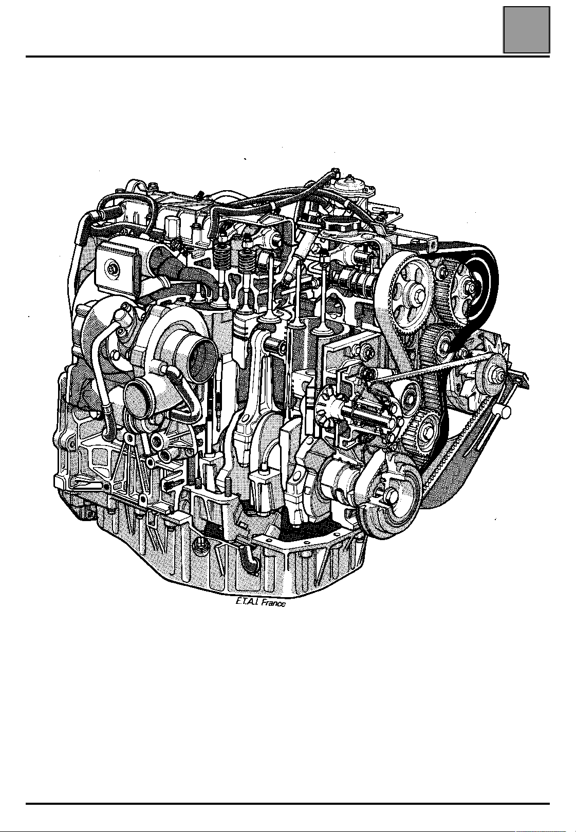
J8S TURBO ENGINE
Diagram
Diagram
10
10-2

ENGINE AND PERIPHERALS
J8S AND 852 ENGINES
Diagram
10
10-3
ENGINE AND PERIPHERALS
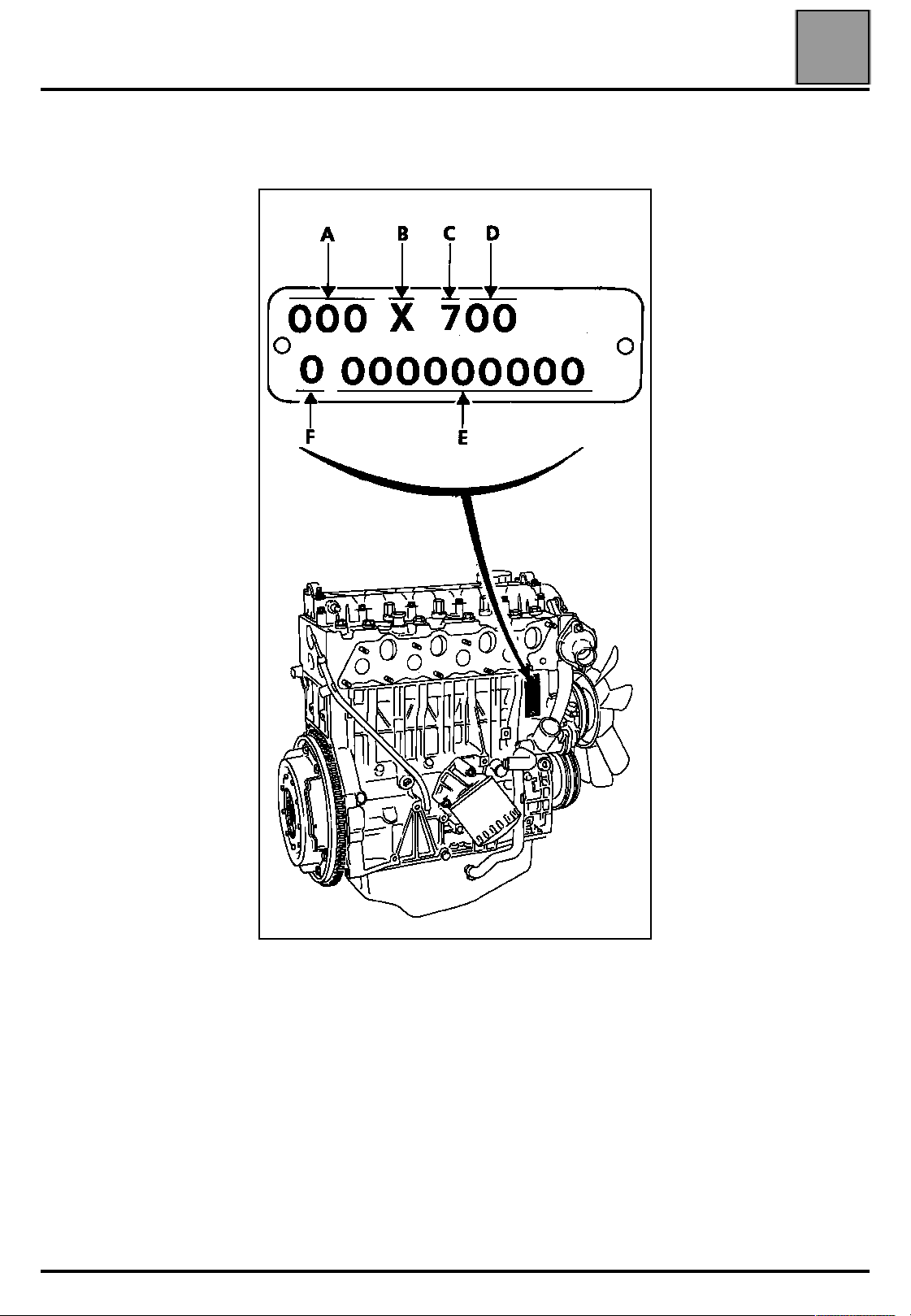
Engine identification
Engine identification
The engine is identified by a plate riveted onto the
cylinder block.
10
It includes:
A: the engine type
B: the engine approval letter
C: the manufacturer code
D: the engine index
E: the engine fabrication number
F: the engine assembly works
10-4
ENGINE AND PERIPHERALS
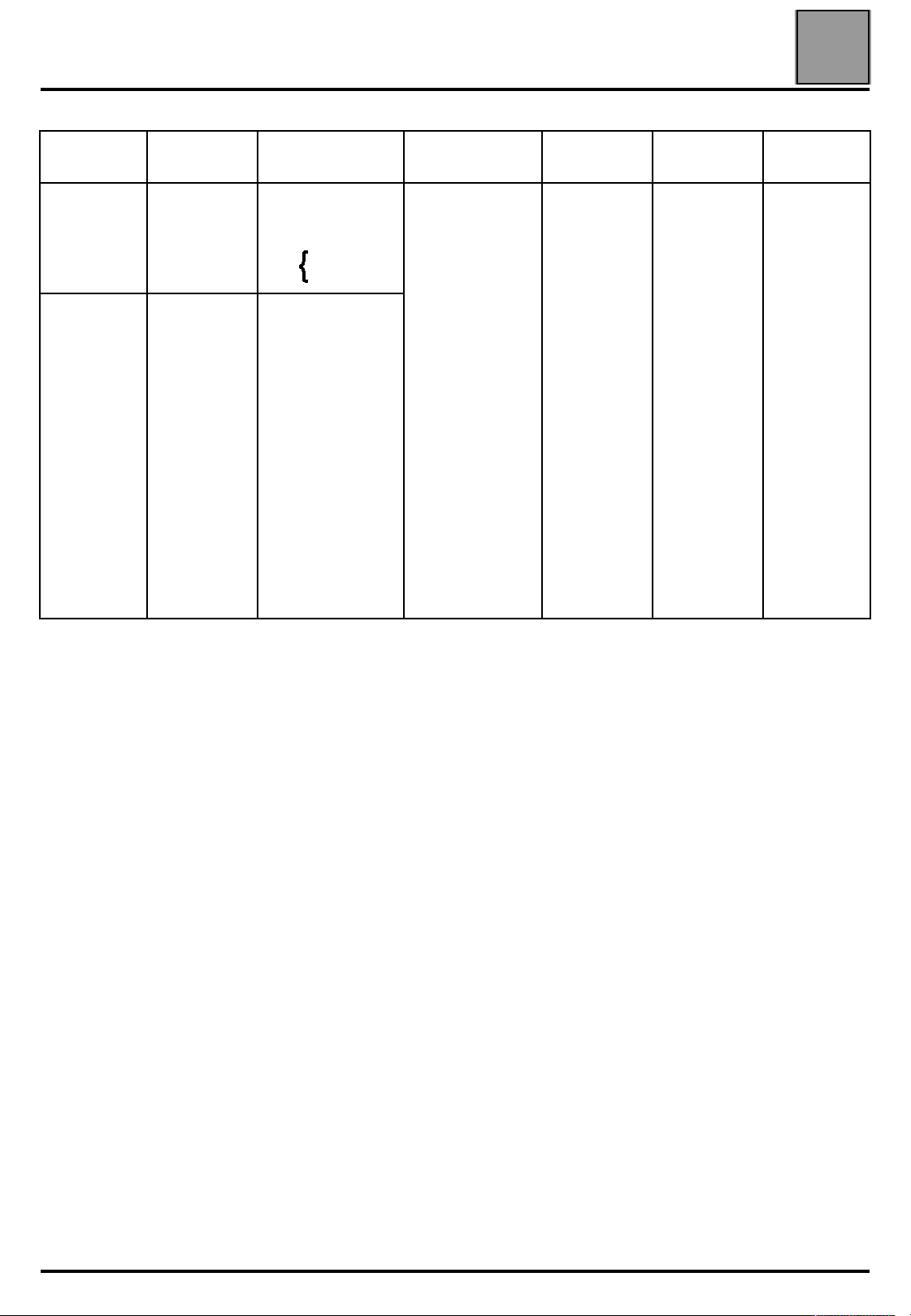
Engine identification
Engine Index Type
852
J8S
700
710
720
750
240
330
600
604
620
622
704
708
714
738
742
746
758
774
786
788
1276
1344, 2354, 1354
Pxx3
Txx3
Vxx3
J115, S115
Rxx3
X480
X48A
PxxF
TxxK
X486
B290
X488
B29W
X488
X486, X48W
TxxF
J114
X487
X48P
Compression
ratio
21/1 86 89 2068
Bore
(in mm)
Stroke
(mm)
10
Capacity
(in cm
3
)
10-5

ENGINE AND PERIPHERALS
Engine identification
Engine Index Type
J63D, S63D
J63E
1270
B296
1344 TA, 1354TA
1346, 1356, 1366
B296
X48, 6, V, V 4x4
B546
J635, S635
J634
J633
X480
CJ
XJ
J8S
J8S
610
612
702
706
711
712
736
740
760
772
776
778
784
800
814
Compression
ratio
21.5/1 86 89 2068
21.5/1 86 89 2068
Bore
(in mm)
Stroke
(in mm)
10
Capacity
(in cm
3
)
10-6
ENGINE AND PERIPHERALS
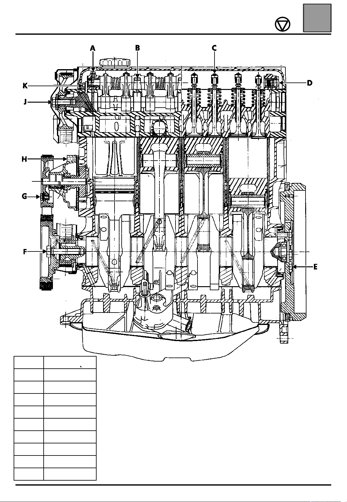
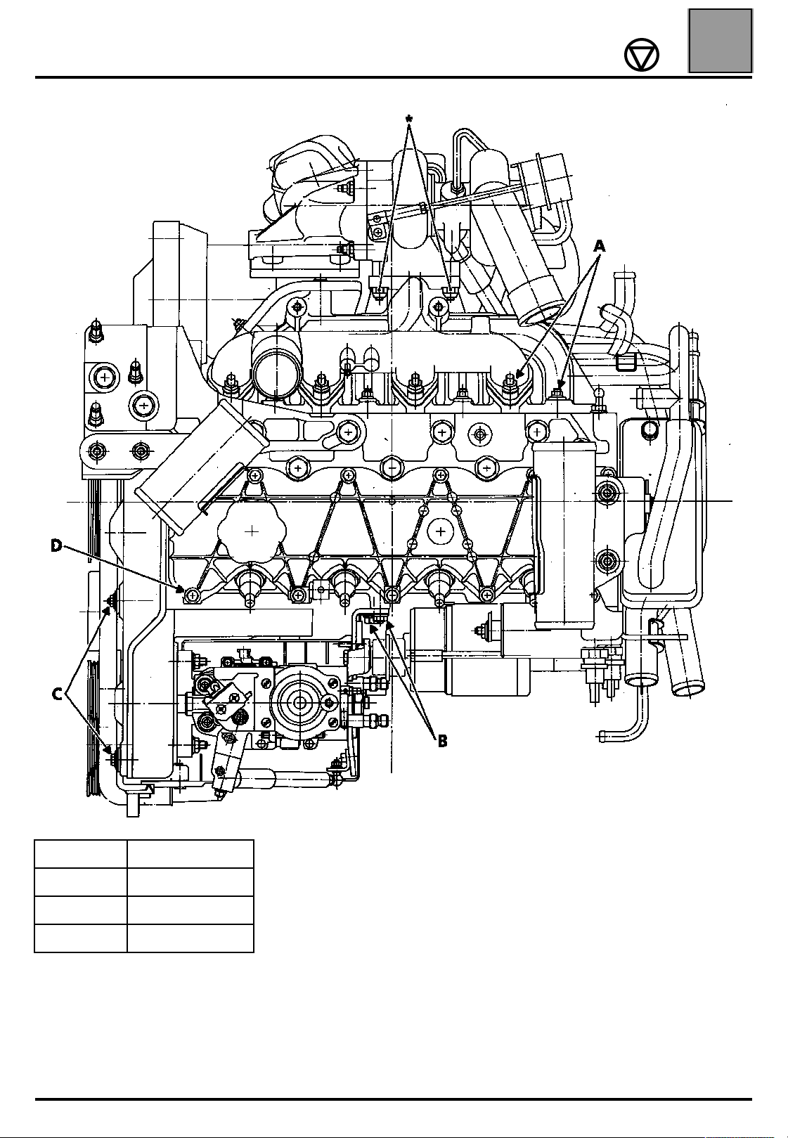
Tightening torques (in daNm)
Tightening torques (in daNm)
10
A 0.5 to 0,9
B 2.5 to 3
C 1.3 to 1.8
D 2
E 6 to 6.5
F 13
G 2.5
H 1.3
J 5
K 1.25
10-7

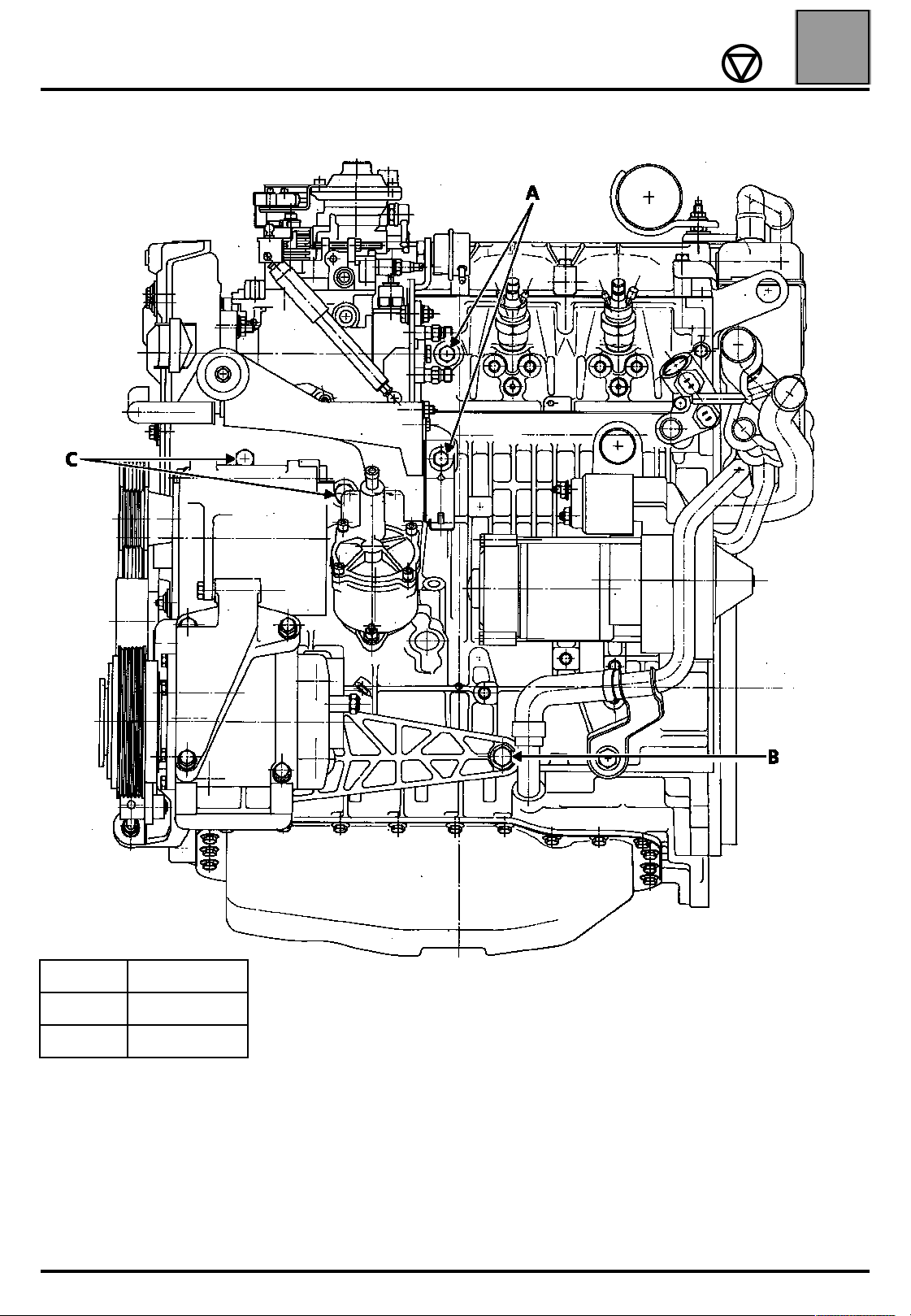
ENGINE AND PERIPHERALS
Tightening torques (in daNm)
CYLINDER BLOCK
10
A 2
B 2
C 2.5
* Preheating shunt nut connector: 0.25 daNm
** Aluminium sump : 1.4 to 1.7 daNm
Metal sump : 1.25 daNm
10-8
ENGINE AND PERIPHERALS
Tightening torques (in daNm)
10
A 3.2 to 3.9
B 2
C 1.3
D 1.4
* Turbo:
IHI : 4.5 daNm
Garrett : 2.6 daNm
10-9
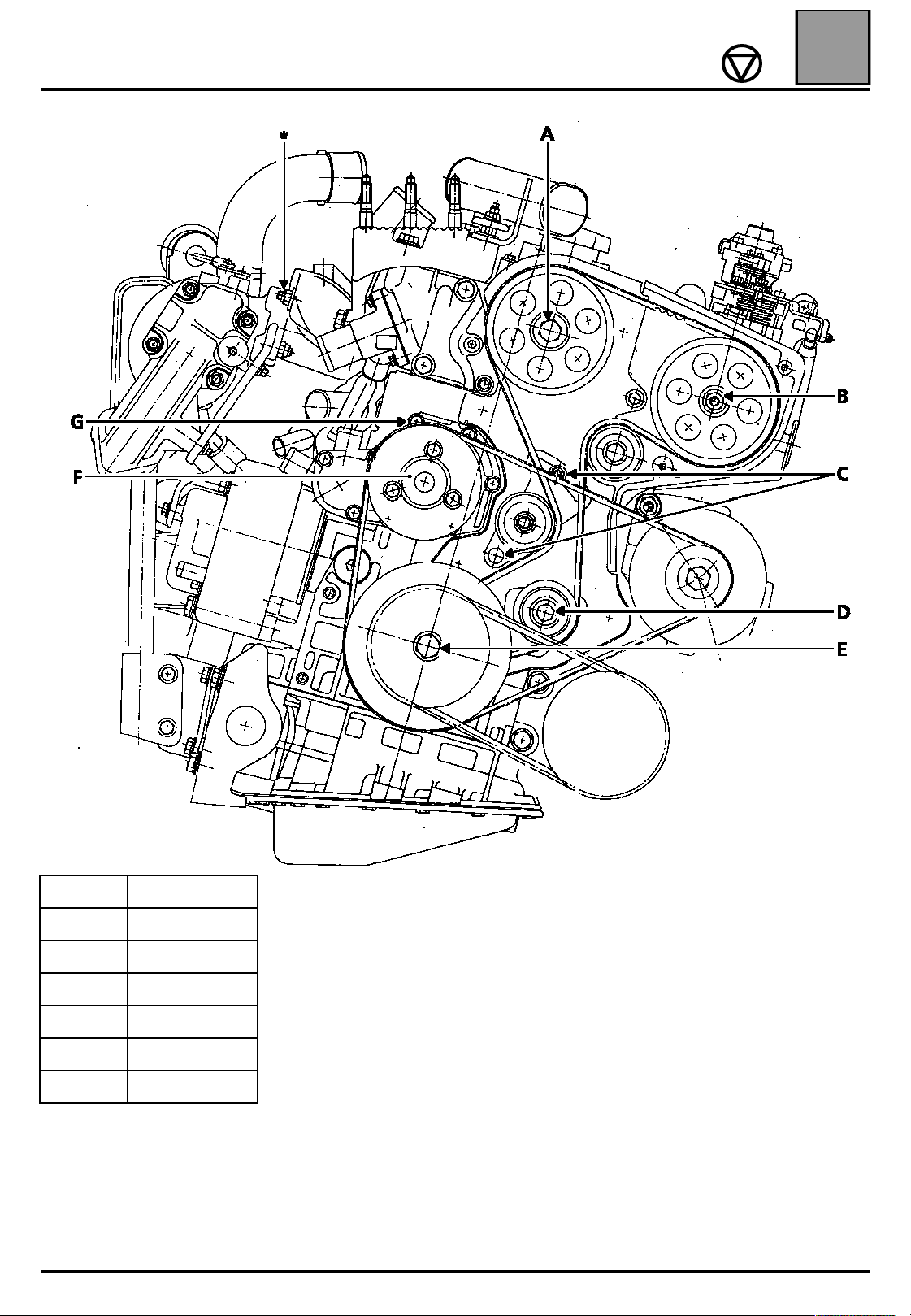
ENGINE AND PERIPHERALS
Tightening torques (in daNm)
10
A 5
B 5
C 2.25 to 2.75
D 5
E 13
F 2.5
G 1.3
* Turbo:
IHI : 4.5 daNm
Garrett : 2.6 daNm
10-10
ENGINE AND PERIPHERALS
Tightening torques (in daNm)
10
A 2
B 4
C 5 to 5.5
10-11
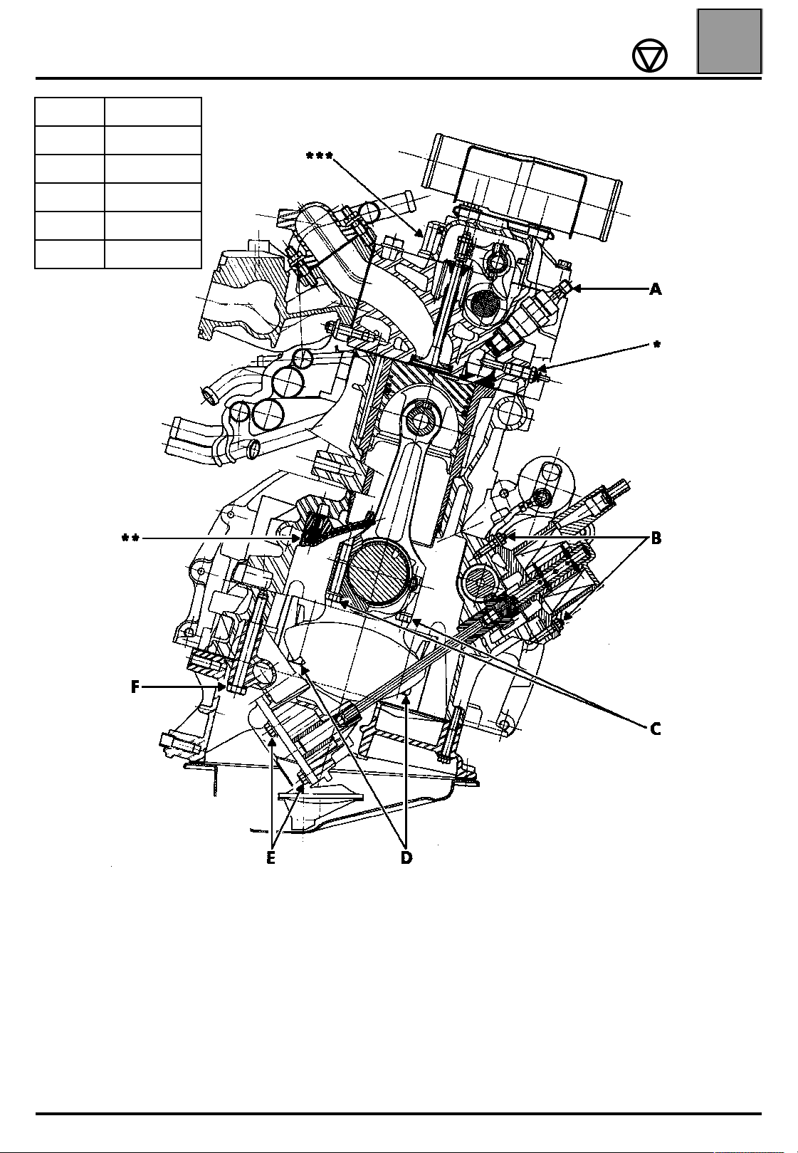
ENGINE AND PERIPHERALS
A 7
B 2.3
C 6.5±0.25
D 8.75 to 9.75
E 1.3
F 4 to 4.5
Tightening torques (in daNm)
10
* Spark plug M12 tighten to 2 daNm
Spark plug M10 tighten to 1.6 daNm
st
** 1
*** Seethe cylinder head tightening procedure page 10-16
model:
– coolant pipe : 0.8 to 1 daNm
– coolant rail : 2 to 2.5 daNm
nd
model:
2
– cooling jets only : 1.2 to 1.4 daNm
10-12

ENGINE AND PERIPHERALS
Tightening torques (in daNm)
10
A 3.2 to 3.9
B 8.75 to 9.75
C 2.5 to 3
D 3
E 2.3
* Turbo:
IHI : 4.5 daNm
Garrett : 2.6 daNm
10-13

ENGINE AND PERIPHERALS
Key:
All types
Turbo with radiator
Turbo with heat
exchanger
1 returning cooling jets
2 integrated cooling jets
3 integrated cooling jets
st
1
nd
2
fitting
fitting
Lubrication circuit diagram
Lubrication circuit diagram
10
10-14

ENGINE AND PERIPHERALS
Lubrication circuit diagram
10
10-15

ENGINE AND PERIPHERALS
Specifications
Specifications
CYLINDER HEAD
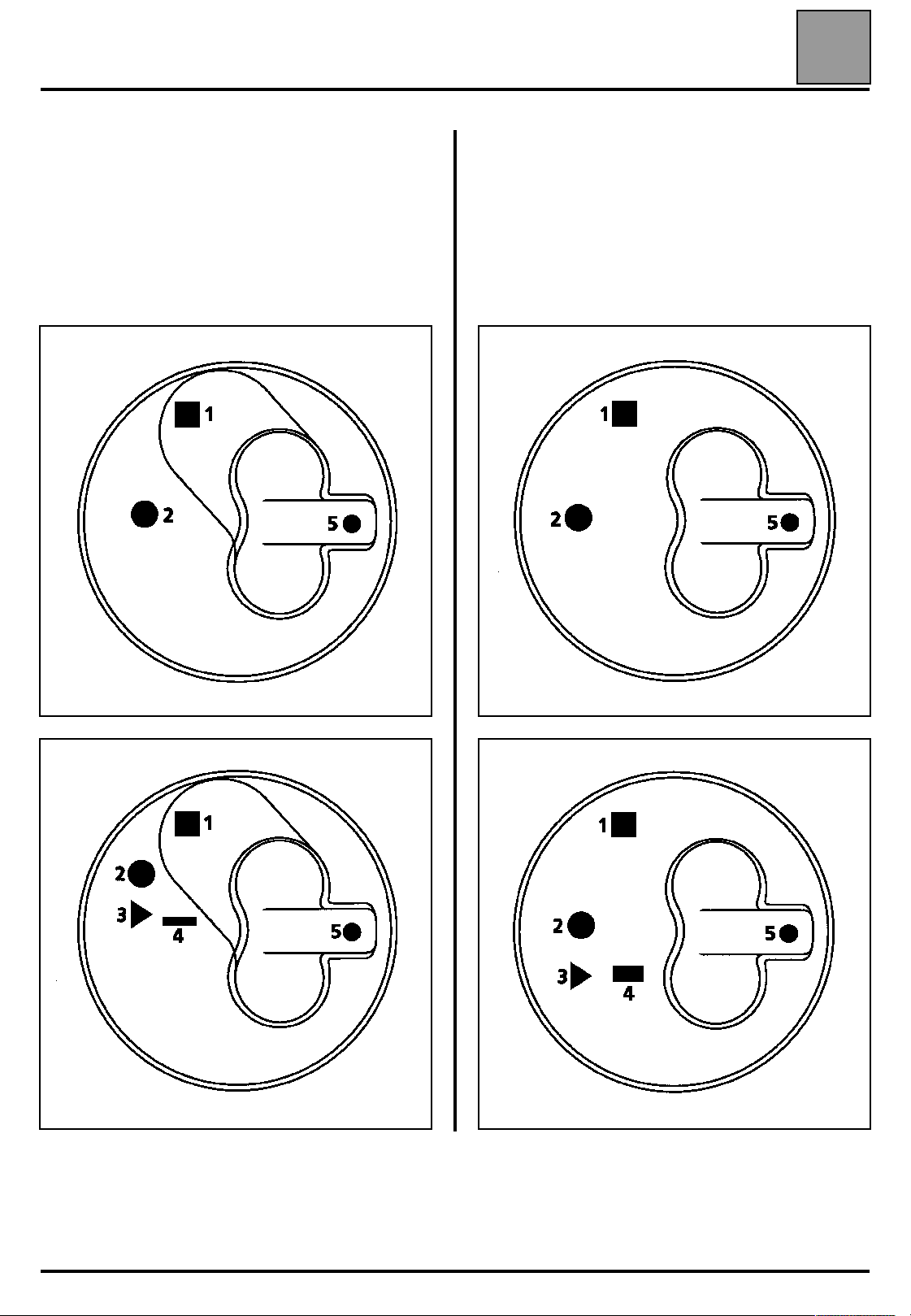
Tightening procedure
All the cylinder head bolts must always be
changed after removal (including the mounting
studs).
Lubricate the threads and under the bolt heads
with engine oil.
REMINDER: Use a syringe to remove any oil which
may have entered the cylinder head mounting bolt
holes to achieve correct tightening of the bolts.
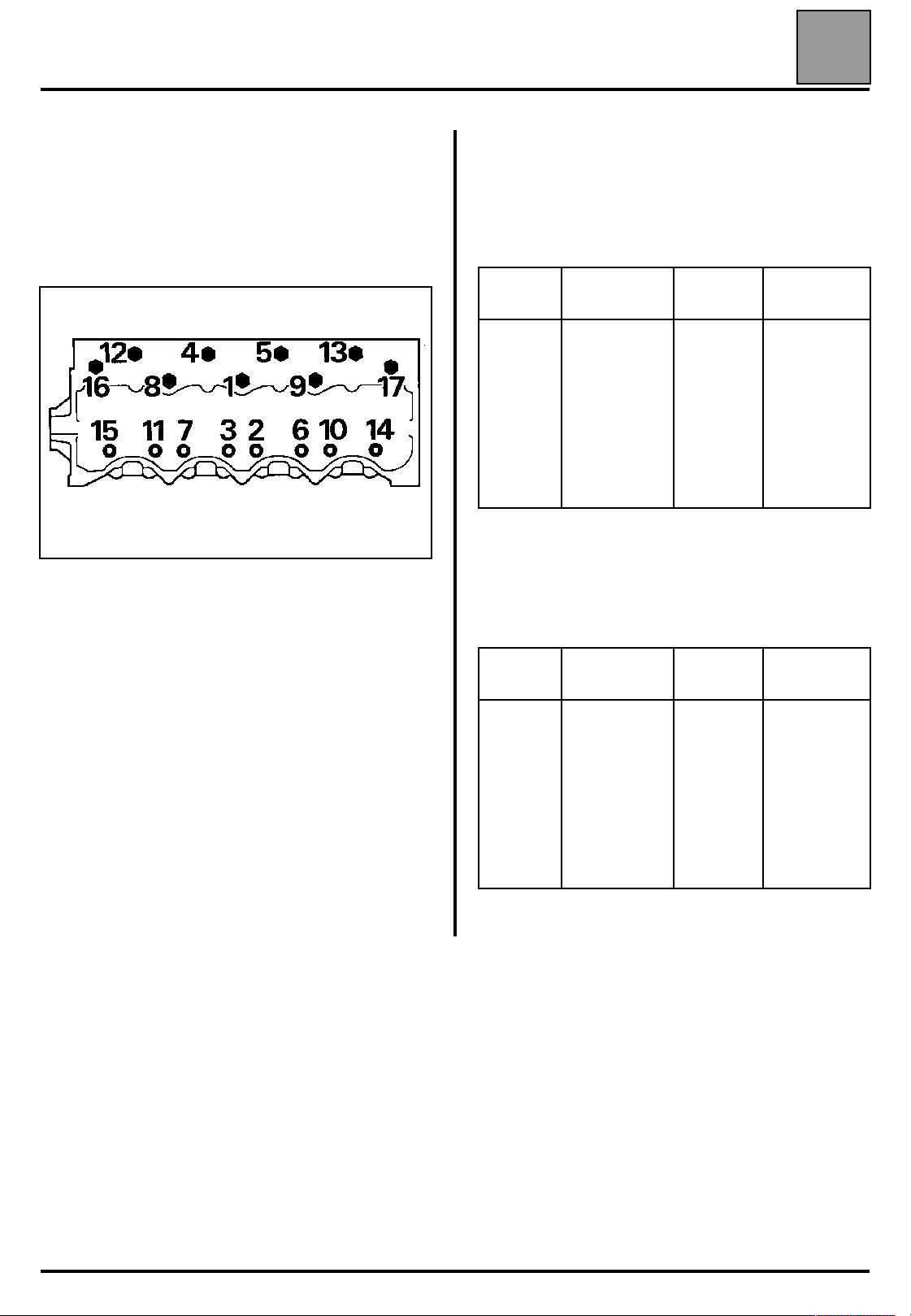
J8S transverse engine
Carry out the following in the order prescribed:
10
Unscrew bolt 1 until it is completely free, and then
carry out:
st
1
retightening 2 daNm
nd
retightening (angle) according to the table:
2
Symbol
1
2
3
4
5
6
7
8
9
Angle
(in degrees)
105
60
60
80
70
60
60
105
105
Symbol
10
11
12
13
14
15
16
17
Angle
(in degrees)
60
60
80
70
60
60
90
80
st
tightening : 3 daNm
1
nd
2
tightening : 5 daNm
Wait 3 minutes settling time.
83174S2
Repeat the above operation for all the bolts.
nd
retightening (angle) according to the table:
3
Symbol
1
2
3
4
5
6
7
8
9
There is no cylinder head retightening operation.
Angle
(in degrees)
105
60
60
80
70
60
60
105
105
Symbol
10
11
12
13
14
15
16
17
Angle
(in degrees)
60
60
80
70
60
60
90
80
10-16
ENGINE AND PERIPHERALS
J8S longitudinal engine
Carry out the following in the order prescribed:
st
tightening : 3 daNm
1
nd
tightening: 5 daNm
2
Specifications
Unscrew bolt 1 until it is completely free, and then
carry out:
st
retightening 2 daNm
1
nd
retightening (angle) according to the table:
2
Symbol
1
2
3
4
5
6
7
8
9
Angle
(in degrees)
105
60
60
70
70
60
60
105
105
Symbol
10
11
12
13
14
15
16
17
10
Angle
(in degrees)
60
60
70
70
60
60
80
80
Wait 3 minutes settling time.
83174S2
Repeat the operation for all the bolts.
nd
3
retightening (angle) according to the table:
Symbol
1
2
3
4
5
6
7
8
9
There is no cylinder head retightening operation.
Angle
(in degrees)
105
60
60
70
70
60
60
105
105
Symbol
10
11
12
13
14
15
16
17
Angle
(in degrees)
60
60
70
70
60
60
80
80
10-17
ENGINE AND PERIPHERALS
Specifications
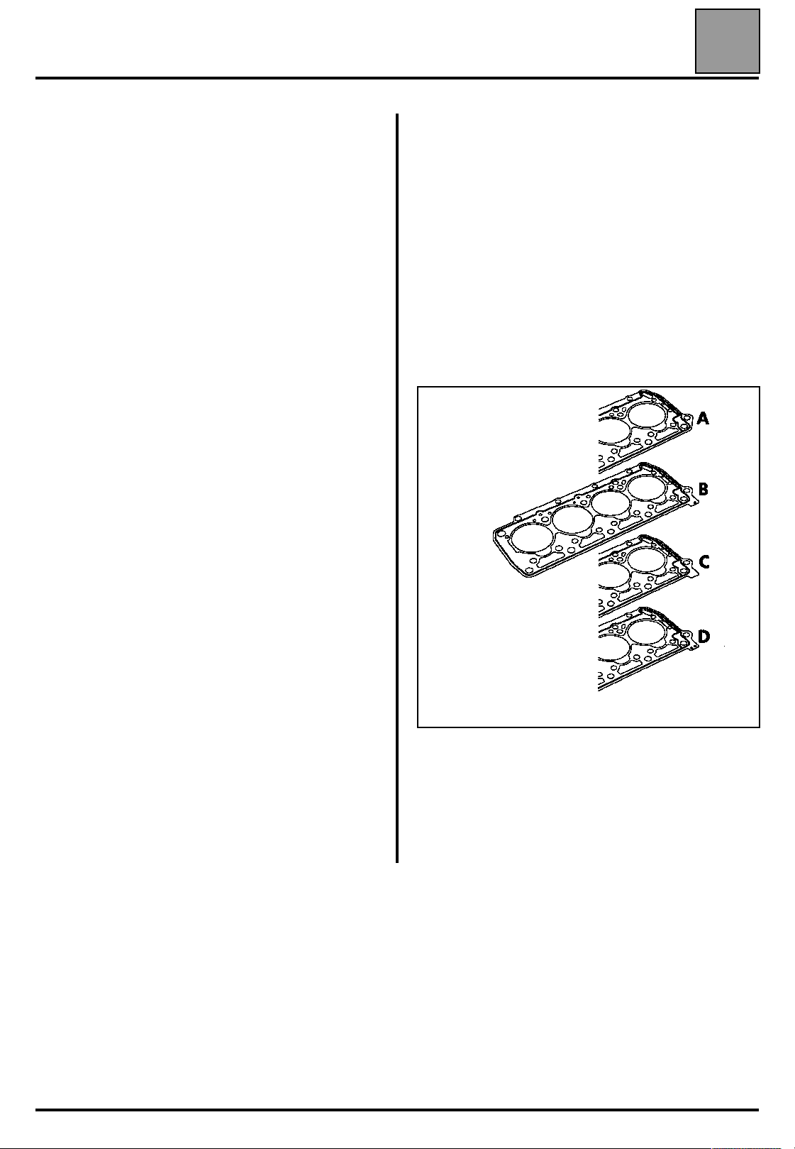
Thickness of the cylinder head gasket
There are several different thicknesses of cylinder
head gasket as replacements. When the 1 model (A)
gaskets have been used up, the Parts Store will only
deliver 2
st
1
On engines fitted with a 1
gasket (marked A on the drawing opposite), the label
showing the gasket thickness cannot be seen from the
outside. The thickness of the gasket must therefore be
calculated before each operation.
Cylinder head gasket thickness 1.6 mm:
– 1.6 is stamped on the gasket.
Cylinder head gasket thickness 1.7 mm:
– not stamped.
model
nd
model (B, C or D) gaskets.
st
model cylinder head
10
nd
2
model
nd
On engines fitted with a 2
gasket, the label showing the gasket thickness can be
seen from the outside. There is no need to recalculate
the gasket thickness if the operations performed have
not involved modifying the piston protrusion
dimension.
B - Cylinder head gasket thickness 1.6 mm:
marked with a hole
C - Cylinder head gasket thickness 1.7 mm:
no hole
D - Cylinder head gasket thickness 1.8 mm:
marked with two holes
model cylinder head
Cylinder head gasket thickness 1.8 mm:
– 1.8 is stamped on the gasket.
16621R
NOTE: if replacing:
– the crankshaft,
– the cylinder block,
– the con rods,
– the pistons,
it is essential to calculate the thickness of the
cylinder head gasket.
10-18
ENGINE AND PERIPHERALS
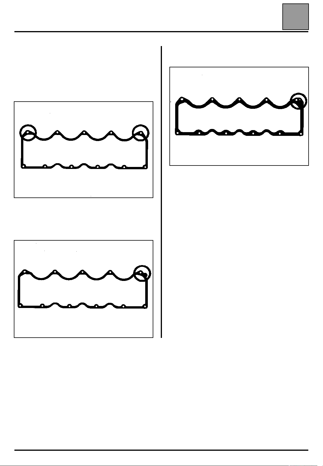
Cylinder head cover gasket
All types except J8S 736
st
model:
1
This gasket is not symmetrical.
Cylinder side graphitised surface.
Specifications
rd
3
model:
same position as the 2
nd
model.
10
93780R
nd
2
model:
This gasket has a an area intended to prevent
confusion; it is located opposite the timing end.
93779-1R
10-19
ENGINE AND PERIPHERALS
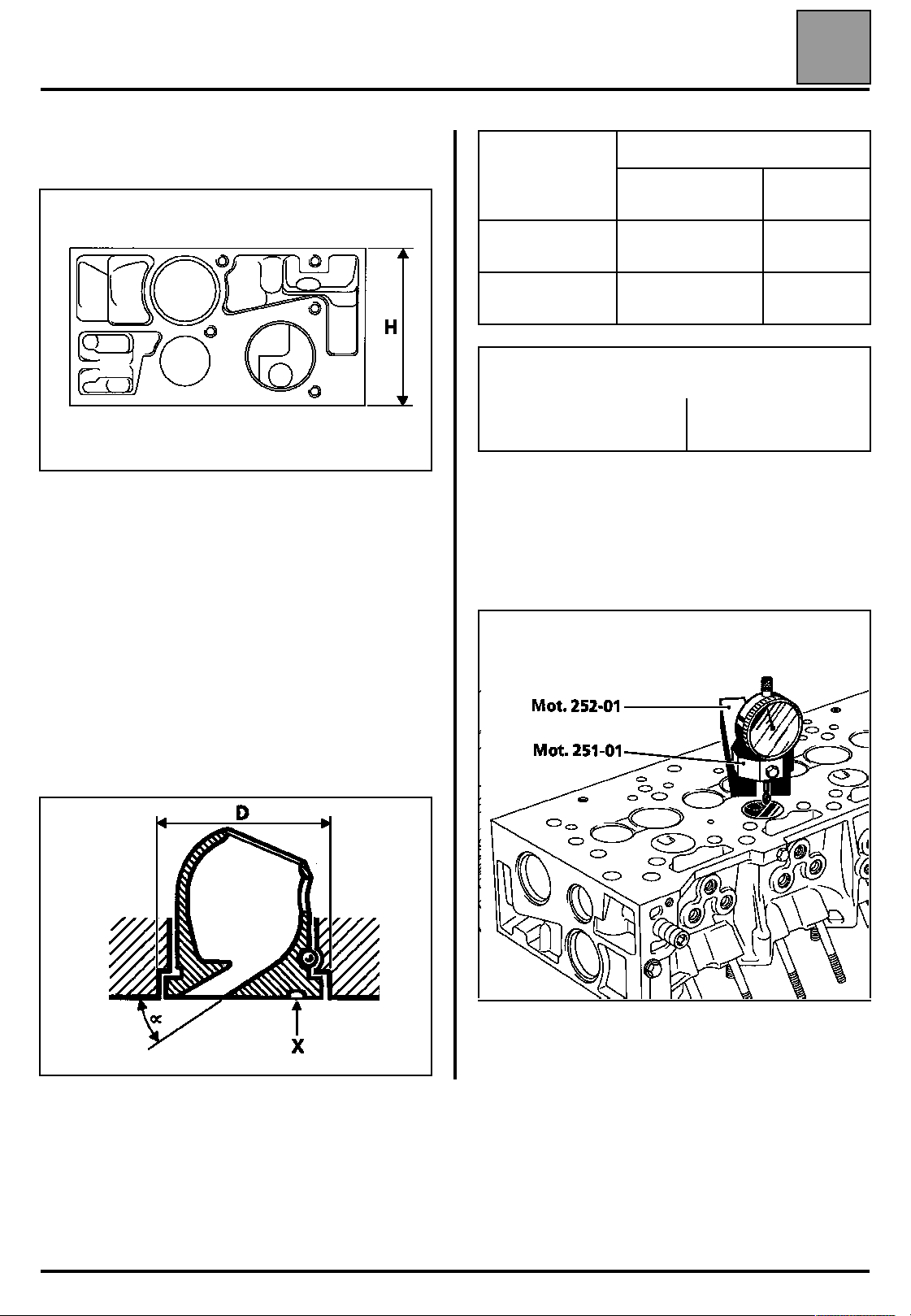
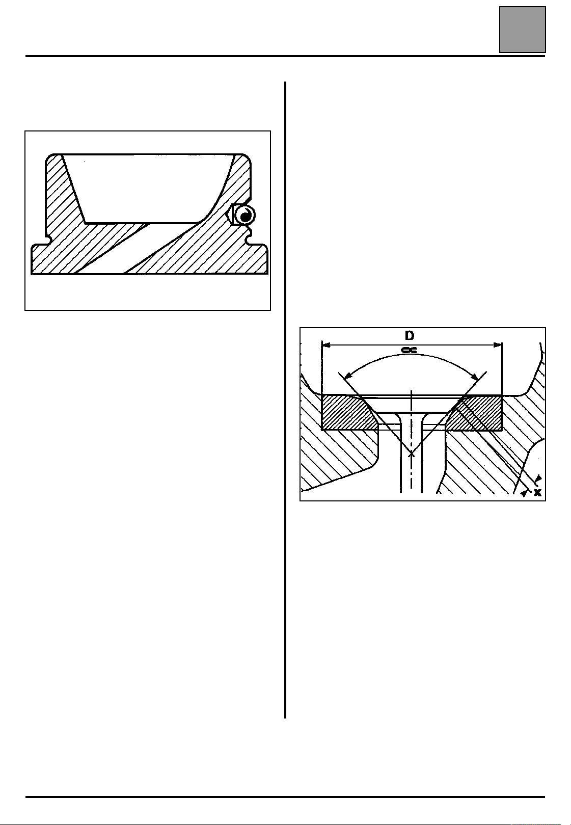
Height of the cylinder head (in mm)
H = 104.5 ± 0.04
NO REDRESSING IS PERMITTED
Specifications
Channel angle
Mark (X) None.
Diameter (D) of the housing in the cylinder head
– Original dimension 1
– Original dimension 2
16721R
Original dimension 2 is exclusively for works-repaired
cylinder head dimensions.
(α)
Engine type
Normally
aspirated
35˚ 31˚
(in mm)
10
Turbo
A drill
stamp
35.5
35.7
Test the cylinder head for cracks. (refer to the mating
face checking section in the Engine overhaul
section).
Maximum mating face deformation 0.05 mm
Prechamber
Assembled prechamber
This is fitted in the cylinder head.
Protrusion in relation to cylinder head:
it should be between 0.01 and 0.04 mm.
16546R
86188-1R
10-20
ENGINE AND PERIPHERALS
Bare prechamber
Half-prechamber
Specifications
Valve seats
Seat angles (
Inlet and exhaust: 90˚
Mating surface width X (in mm)
Inlet and exhaust: 1.75 ± 0.2
External diameter D (in mm)
Inlet: 42
Exhaust: 34.6
92448-1S
10
α
)
+ 0.13
+ 0.11
+ 0.03
+ 0.01
Valves
Stem diameter (in mm)
Inlet: 7.991
Exhaust: 7.978
Setting angle
Head diameter (in mm)
Inlet:
Exhaust:
Maximum valve lift (in mm)
Inlet:
Exhaust:
Valve set back in relation to the
cylinder head mating surface
(in mm)
40.32 ± 0.12
33.32 ± 0.12
+ 0
- 0.02
+ 0
- 0.02
90˚
73928R
See the "Overhauling the engine" section for how to
redress the valve seats.
9.27
8.80
0.80 to 1.15
Valve clearance settings (in mm)
Inlet:
Exhaust:
0.20 ± 0.02
0.25 ± 0.02
10-21
ENGINE AND PERIPHERALS
Specifications
Valve guides
Internal diameter (in mm) 8
External diameter (in mm):
– Normal
– Repair (two grooves)
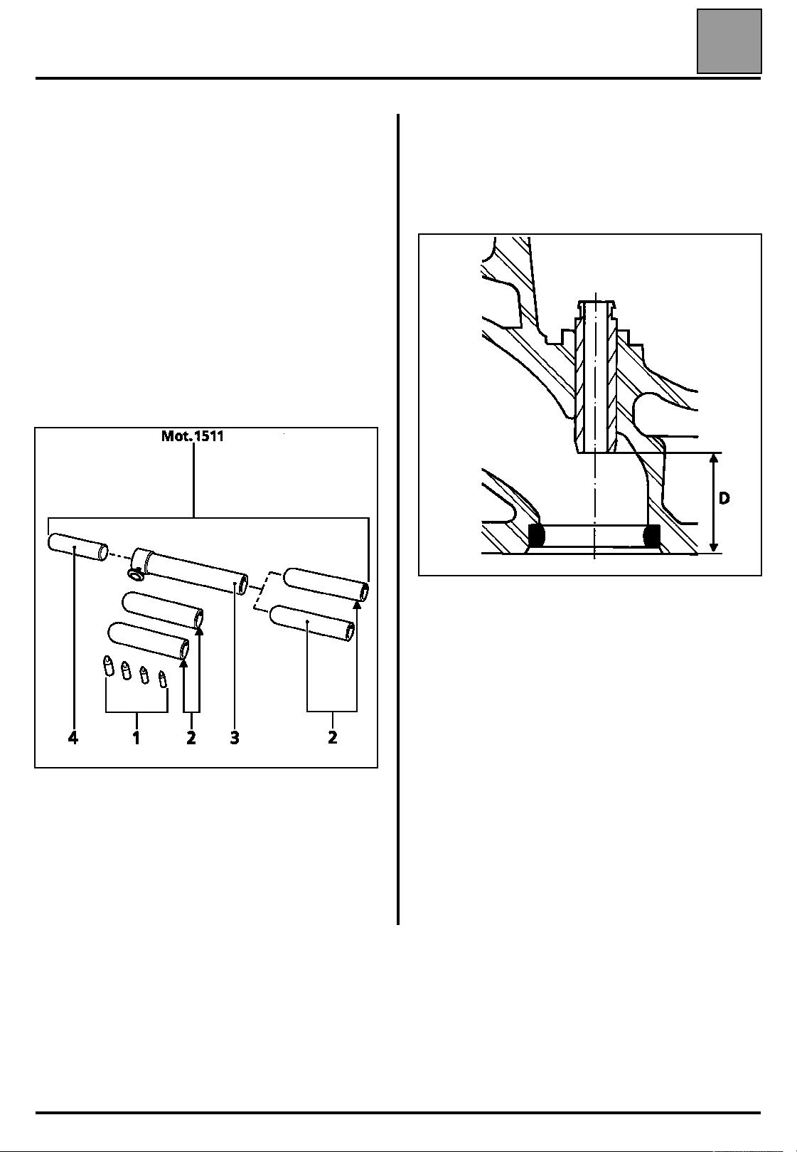
The inlet and exhaust guides have valve stem seals
which must be changed every time the valves are
removed.
The valve stem seals must be fitted using tool
Mot. 1511 or with the FACOM tool, part number
DM6J4 for example.
13.10
13.35
10
Position of the inlet and exhaust valve guides
Position of guides in relation to the cylinder head
mating face (in mm):
D = 32.5
15737R1
NOTE: do not lubricate the valve stem seals before
fitting them.
Mot. 1511 consists of:
– four cores (1),
– four pushrods (2),
– one guide tube (3),
– one sleeve (4).
83172R
The diameter of the housing is smaller
(by approximately 0.1 mm) to obtain the necessary
seal.
It is vital to drill the guide after fitting.
10-22
ENGINE AND PERIPHERALS
Specifications
Valve springs
The inlet and exhaust valve springs are identical.
Free length (in mm): 45.2
Length under a load of (in mm):
23 daNm
60 daNm
Sealing turns (in mm): 27.2
Wire diameter (in mm): 4.25
Internal diameter (in mm): 21.5
Camshaft
39.3
29.8
10
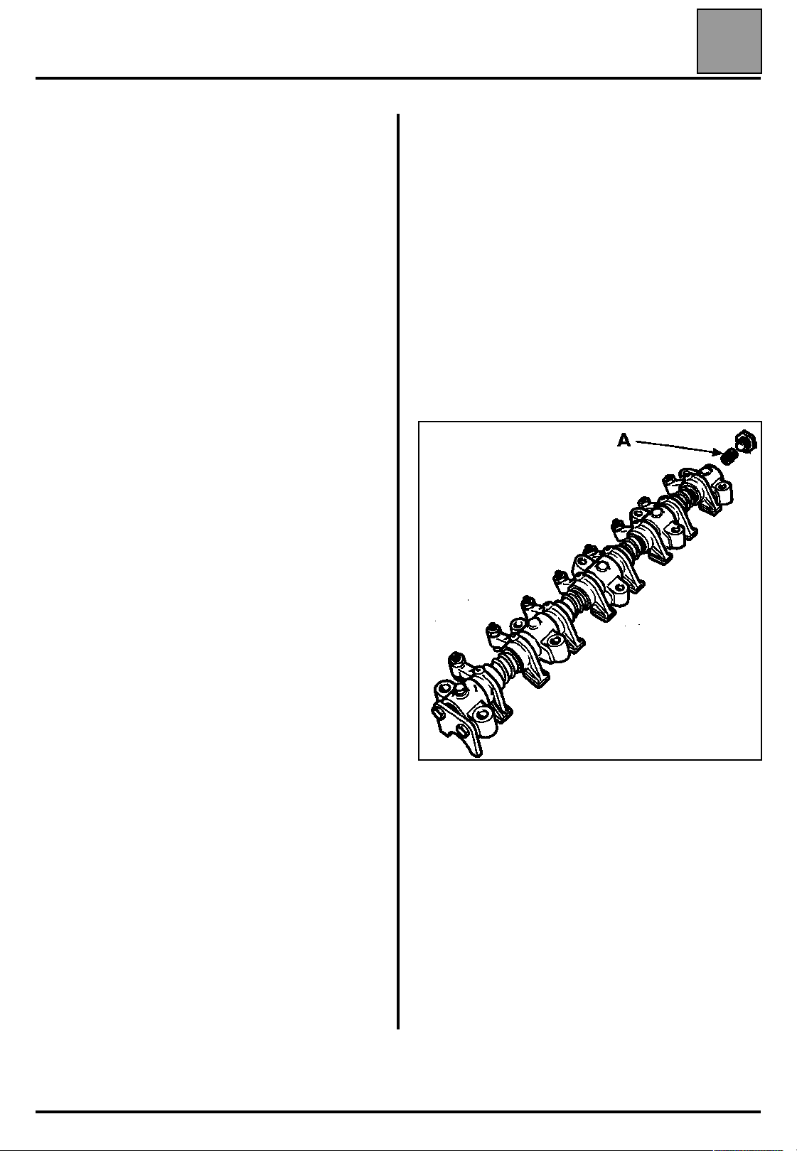
Rocker arm rail
When performing operations on faults that cause
metallic particles to become suspended in the
lubricating oil, e.g.:
– damaged con rod bearing shells or crankshaft,
– parts grating,
it is essential to replace:
– the oil filter (A) located in the rocker arm rail shaft,
– the oil filter located on the main pipe,
– the lubricating oil.
REMINDER: The rocker arm rail filter must be
replaced if an operation requires the removal of the
rocker box cover.
All types except J8S 736 and J8S 740
Longitudinal play (in mm): 0.05 to 0.15
Number of bearings 5
Timing diagram:
– Inlet opening advance
– Inlet closing retardation
– Exhaust opening advance
– Exhaust closing retardation
With a theoretical clearance to the valve stem of
0.35 mm (All types).
Engines J8S 736 and J8S 740
Longitudinal clearance (in mm) 0.05 to 0.15
Number of bearings: 5
Timing diagram:
– Inlet opening advance
– Inlet closing retardation
– Exhaust opening advance
– Exhaust closing retardation
14˚
46˚
50˚
10˚
14˚
46˚
58˚
14˚
The value of the theoretical clearance to the valve
stems is only valid following a check on the timing
diagram and has no relation to the rocker arm
clearances.
10-23
ENGINE AND PERIPHERALS
Specifications
PISTONS
These engines are fitted with Floquet Monopole
pistons.
The gudgeon pin is free in the con rod and in the
piston.
Piston marking
10
16576R
16576-1R
16576-2R
16576-3R
10-24
ENGINE AND PERIPHERALS
Specifications
The paint mark that indicates diameter class is also
present on the piston.
Table of gudgeon pin heights
Classes and marks on
piston
H 50.890 to 50.930
K 50.931 to 50.970
M 50.971 to 51.010
P 51.011 to 51.050
R 51.051 to 51.090
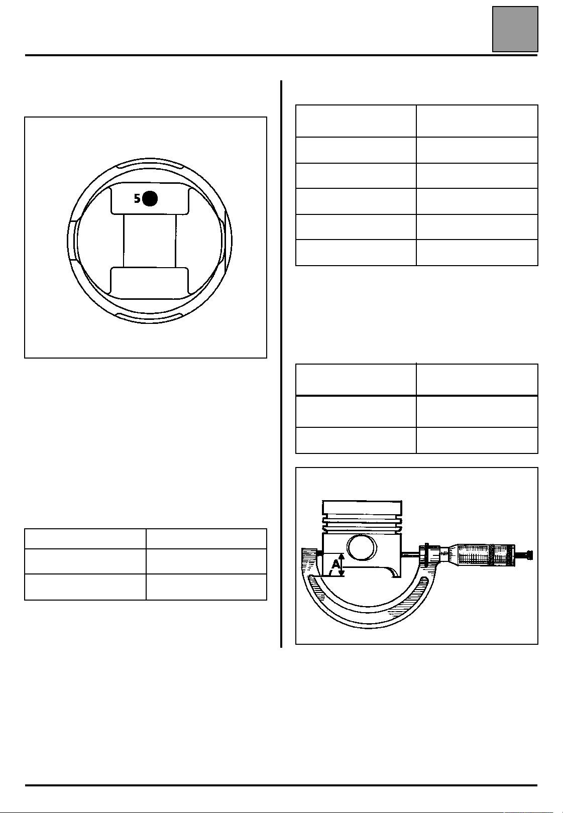
Measuring the piston diameter
10
Shaft height
(in mm)
16577R
1 Height between the gudgeon pin and the top of the
piston (see table below).
2 Modification index, for supplier's use only.
3 For supplier's use only.
4 Dater, for supplier's use only.
5 Diameter class mark, paint mark (see following
table).
Table of piston diameter classes
Piston mark Piston diameter (in mm):
Blue 85.875 to 85.890
Red 85.890 to 85.905
The diameter of the piston (86 mm diameter) should
be measured at position:
Engine type
J8S 852
normally aspirated
J8S Turbo 24
Piston measuring
point (A) (in mm)
24.35
10-25
86928-4R1
ENGINE AND PERIPHERALS
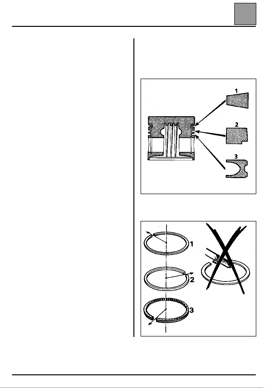
Rings
Three rings (thickness in mm)
Normally aspirated engine
– Compression
– Sealing
– Scraper
Turbo engine
– Compression
– Sealing
– Scraper
Gudgeon pin (in mm)
– Length:
– External diameter:
– Internal diameter:
2
2
2
2.5
2.5
4
Specifications
(tapered)
(rounded)
(trapezoidal)
(trapezoidal)
(rounded)
75
28
16
10
FITTING THE RINGS
Rings set to their original adjustment must be free
within their channels.
Ensure the fitting direction is observed.
Fit the rings so that the gaps are equally spaced
around the piston.
86187R
10-26
72552R

ENGINE AND PERIPHERALS
Specifications
CON RODS
in mm
Lateral play in the big end 0.31 to 0.57
Centre-to-centre distance between
big end and small end
Big end diameter 60
Small end diameter
without ring 30
●
with ring 28
●
The small end has a bush.
155 ± 0.035
+ 0.019
- 0.005
+ 0.021
0
+ 0.01
+ 0.003
10
Refitting and assembling con rods and pistons
Direction of fitting:
rotochamber on the injector side or the side opposite
the oil filter.
Check that the gudgeon pins rotate properly in the new
piston and the con rod.
Oil the gudgeon pin.
Ensure that the piston and con rod are fitted the right
way around (follow the arrows):
Engines 852 J8S all types except turbo
N.B.: the small end bushes cannot be replaced or redrilled.
WARNING: do not use a sharp point to mark the
bearing caps in relation to their con rods as this could
start a crack in the rods. Use an indelible marker pen.
Normally aspirated engine
The big end and the half bearing are pierced to allow
an oil jet to pass through.
Turbo engine
The con rods do not have a hole for an oil jet. The
upper and lower bearing shells are not pierced.
Turbo engine
10-27
ENGINE AND PERIPHERALS
Specifications
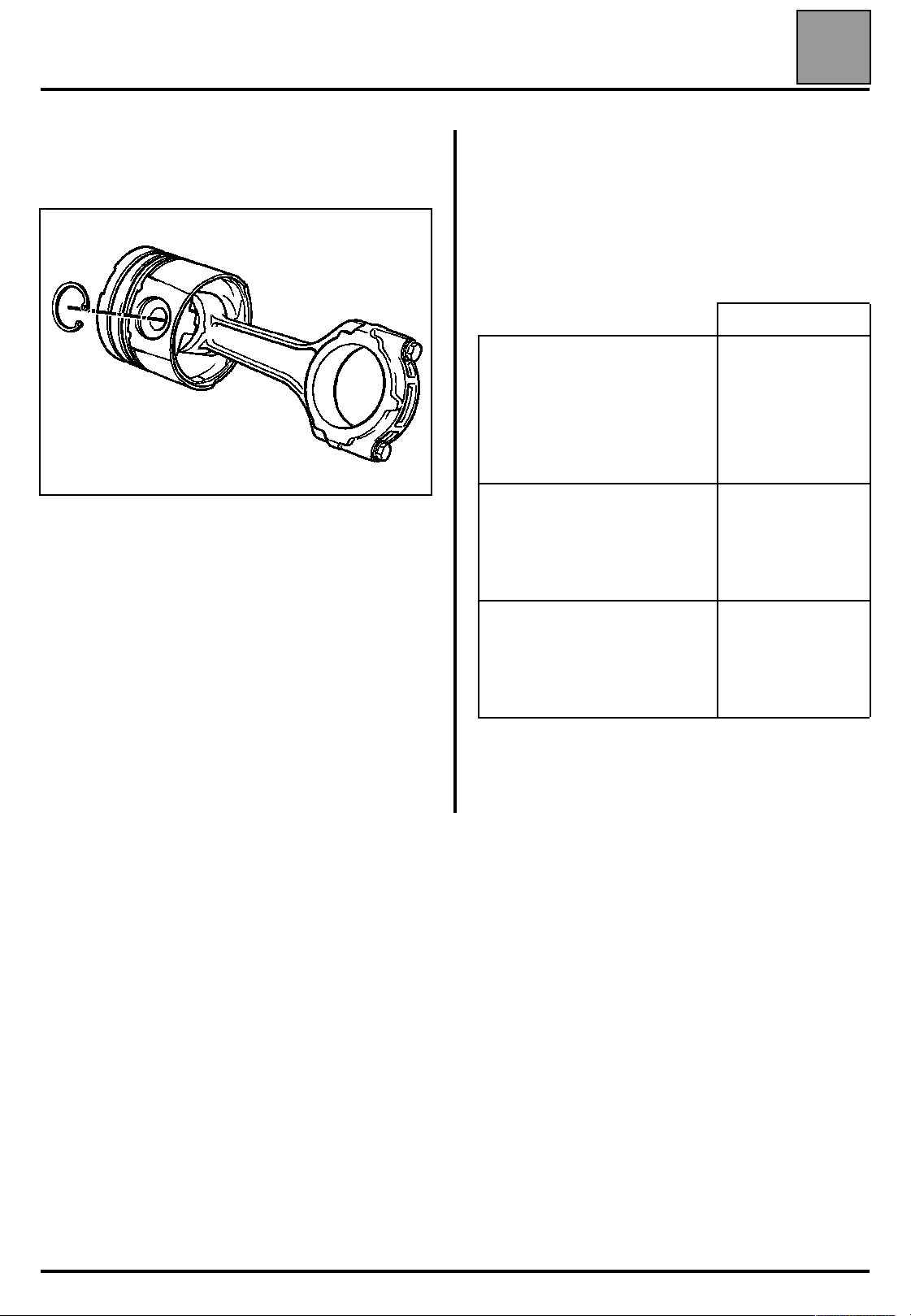
Direction for fitting the circlips on the piston
Fit the circlips on the piston as shown below.
98365S
10
CRANKSHAFT
Number of bearings 5
Burnishing
normally aspirated engine with
●
turbo engine 1st fitting without
●
turbo engine 2nd fitting with
●
in mm
Longitudinal play
normally aspirated engine
●
st
1
model: 1 to 32 909
normally aspirated engine
●
nd
2
model: from 32 910
turbo engine
●
st
1
Bushing
Nominal diameter
Repair diameter
and 2
nd
models
62.88
62.63
0.07 to 0.25
0.20 to 0.30
0.20 to 0.30
- 0
- 0.019
- 0
- 0.019
Crankpin
Nominal diameter
Repair diameter
N.B.: non-burnished crankshafts fitted on turbo
engines can be redressed using the values given in
the table.
56.296
56.046
- 0.010
- 0.029
- 0.010
- 0.029
10-28
Loading...