


 Loading...
1 Engine and peripherals
10A
11A
12A
12B
13A
13B
13C
14A
16A
17A
17B
ENGINE AND CYLINDER BLOCK ASSEMBLY
TOP AND FRONT OF ENGINE
FUEL MIXTURE
TURBOCHARGING
FUEL SUPPLY
DIESEL INJECTION
PREHEATING
ANTIPOLLUTION
STARTING - CHARGING
IGNITION
PETROL INJECTION
X74
FEBRUARY 2009 |
Edition Anglaise |
"The repair methods given by the manufacturer in this document are based on the technical specifications current when it was prepared.
The methods may be modified as a result of changes introduced by the manufacturer in the
production of the various component units and accessories from which his vehicles are constructed."
All copyrights reserved by Renault.
The reproduction or translation in part of whole of the present document, as well as the use of the spare parts reference numbering system, are prohibited without the prior written consent of Renault.
© Renault s.a.s 2008

19A
19B
19C
19D
COOLING
EXHAUST
TANK
ENGINE MOUNTING
X74
FEBRUARY 2009 |
Edition Anglaise |
"The repair methods given by the manufacturer in this document are based on the technical specifications current when it was prepared.
The methods may be modified as a result of changes introduced by the manufacturer in the
production of the various component units and accessories from which his vehicles are constructed."
All copyrights reserved by Renault.
The reproduction or translation in part of whole of the present document, as well as the use of the spare parts reference numbering system, are prohibited without the prior written consent of Renault.
© Renault s.a.s 2008

LAGUNA II Phase II and Phase I update - Section 1
Contents
|
|
Page |
|
ENGINE AND CYLINDER BLOCK |
|
10A |
|
|
ASSEMBLY |
|
|
|
|
|
|
Engine: Specifications |
10A-1 |
|
||
|
Crankshaft seal at timing end |
|
|
Removal - Refitting |
10A-16 |
|
Crankshaft seal at gearbox |
|
|
end : Removal - Refitting |
10A-25 |
|
Engine oil: Specifications |
10A-35 |
|
Engine oil: Draining - |
|
|
Refilling |
10A-62 |
|
Oil consumption Check |
10A-77 |
|
Oil filter: Removal - Refitting |
10A-78 |
|
Oil filter unit: Removal - |
|
|
Refitting |
10A-85 |
|
Exchanger: Removal - |
|
|
Refitting |
10A-94 |
|
Oil pressure sensor: |
|
|
Removal - Refitting |
10A-98 |
|
Oil level sensor: Removal - |
|
|
Refitting |
10A-106 |
|
Sump: Removal - Refitting |
10A-114 |
|
Conrod bearing shell: |
|
|
Removal - Refitting |
10A-130 |
|
Oil pump: Removal - |
|
|
Refitting |
10A-141 |
|
Multifunction support: |
|
|
Removal - Refitting |
10A-154 |
|
Engine/gearbox assembly: |
|
|
Removal - Refitting |
10A-162 |
|
Oil pressure: Check |
10A-272 |
11A |
TOP AND FRONT OF ENGINE |
|
|
Final compression pressure: |
|
|
|
|
|
Check |
11A-1 |
|
Accessories belt: Removal - |
|
|
Refitting |
11A-4 |
|
Crankshaft accessories |
|
|
pulley: Removal - Refitting |
11A-16 |
|
Timing belt: Removal - |
|
|
Refitting |
11A-26 |
|
Timing chain: Removal - |
|
|
Refitting |
11A-131 |
|
Rocker cover: Removal - |
|
|
Refitting |
11A-142 |
|
Camshaft dephaser: |
|
|
Function |
11A-181 |
|
Camshaft dephaser: |
|
|
Description |
11A-183 |
|
Camshaft: Removal - |
|
|
Refitting |
11A-185 |
|
Camshaft dephaser: |
|
|
Removal - Refitting |
11A-224 |
|
Camshaft seal at timing end: |
|
|
Removal - Refitting |
11A-227 |
|
Cylinder head: Removal - |
|
|
Refitting |
11A-239 |
|
Cylinder head: Removal - |
|
|
Refitting |
11A-245 |
|
Oil decanter: Removal - |
|
|
Refitting |
11A-288 |

Contents
12A |
FUEL MIXTURE |
|
|
Air inlet |
12A-1 |
|
||
|
Air intake: Description |
12A-8 |
|
Air resonator: Removal - |
|
|
Refitting |
12A-15 |
|
Air filter: Replacement |
12A-19 |
|
Air filter: Removal - Refitting |
12A-21 |
|
Air filter unit: Removal - |
|
|
Refitting |
12A-28 |
|
Air flowmeter: Removal - |
|
|
Refitting |
12A-38 |
|
Engine damper flap: |
|
|
Removal - Refitting |
12A-41 |
|
Air inlet flap: Removal - |
|
|
Refitting |
12A-43 |
|
Throttle valve: Removal - |
|
|
Refitting |
12A-47 |
|
Air inlet duct: Removal - |
|
|
Refitting |
12A-55 |
|
Inlet manifold: Removal - |
|
|
Refitting |
12A-59 |
|
Exhaust manifold - Intake |
|
|
distributor: Removal - |
|
|
Refitting |
12A-62 |
|
Inlet manifold: Removal - |
|
|
Refitting |
12A-71 |
|
Injector holder shim: |
|
|
Removal - Refitting |
12A-84 |
|
Exhaust manifold: Removal - |
|
|
Refitting |
12A-87 |
12B |
TURBOCHARGING |
|
|
Turbocharging: Precautions |
|
|
|
|
|
for repair |
12B-1 |
|
Turbocharger: Removal - |
|
|
Refitting |
12B-4 |
|
Turbocharger oil pipe: |
|
|
Removal - Refitting |
12B-41 |
Pressure regulator: Checking
12B |
TURBOCHARGING |
|
|
Turbocharging pressure |
|
|
|
|
|
regulation valve |
12B-55 |
|
Intercooler: Removal - |
|
|
Refitting |
12B-56 |
13A |
FUEL SUPPLY |
|
|
Petrol supply system: |
|
|
|
|
|
Operating diagram |
13A-1 |
|
Petrol filter: Removal - |
|
|
Refitting |
13A-2 |
|
Manual priming pump: |
|
|
Removal - Refitting |
13A-3 |
|
Fuel filter: Removal - |
|
|
Refitting |
13A-5 |
|
Injector rail - Injectors: |
|
|
Removal - Refitting |
13A-11 |
|
Fuel pressure: check |
13A-18 |
|
Fuel flow: check |
13A-20 |
13B |
DIESEL INJECTION |
|
|
Diesel injection: Precautions |
|
|
|
|
|
for repair |
13B-1 |
|
Diesel injection: List and |
|
|
location of components |
13B-10 |
|
Diesel injection computer: |
|
|
Removal - Refitting |
13B-28 |
|
Camshaft position sensor: |
|
|
Removal - Refitting |
13B-35 |
|
Crankshaft position sensor: |
|
|
Removal - Refitting |
13B-37 |
|
High pressure pump: |
|
|
Removal - Refitting |
13B-40 |
|
Fuel pressure regulator: |
|
|
Removal - Refitting |
13B-59 |
|
Diesel return pipe: Removal - |
|
|
Refitting |
13B-66 |

Contents
13B |
DIESEL INJECTION |
|
14A |
ANTIPOLLUTION |
|
|
Diesel injector fuel return rail: |
|
|
Exhaust gas recirculation: |
|
|
|
|
|
||
|
Removal - Refitting |
13B-71 |
Operating diagram |
14A-8 |
|
|
Injector rail protector: |
|
|
Fuel vapour recirculation |
|
|
Removal - Refitting |
13B-79 |
circuit: check |
14A-11 |
|
|
High-pressure pipe between |
|
|
Fuel vapour canister: |
|
|
the pump and rail: Removal - |
|
|
Removal - Refitting |
14A-13 |
|
Refitting |
13B-94 |
Fuel vapour |
|
|
|
|
|
|
|
|
|
High-pressure pipe between |
|
|
canister:Checking |
14A-14 |
|
the rail and injector: Removal |
|
|
Exhaust gas recirculation |
|
|
- Refitting |
13B-106 |
|
||
|
unit: Removal - Refitting |
14A-15 |
|||
|
|
|
|
||
|
Injector rail: Removal - |
|
|
Exhaust gas recirculation |
|
|
Refitting |
13B-116 |
|
||
|
solenoid valve: Removal - |
|
|||
|
|
|
|
|
|
|
Rail pressure sensor: |
|
|
Refitting |
14A-18 |
|
Removal - Refitting |
13B-128 |
Intercooler: Removal - |
|
|
|
|
|
|
|
|
|
Oxygen sensor: Removal - |
|
|
Refitting |
14A-29 |
|
Refitting |
13B-136 |
Exhaust gas recirculation |
|
|
|
|
|
|
|
|
|
Fuel temperature sensor: |
|
|
rigid pipe: Removal - |
|
|
Removal - Refitting |
13B-138 |
Refitting |
14A-39 |
|
|
Diesel injector: Removal - |
|
|
Exhaust gas recirculation |
|
|
Refitting |
13B-141 |
solenoid valve: Cleaning |
14A-43 |
|
13C |
PREHEATING |
|
16A |
STARTING - CHARGING |
|
|
Pre/postheating unit: |
|
|
Starting system: |
|
|
|
|
|
||
|
Removal - Refitting |
13C-1 |
Identification |
16A-1 |
|
|
Heater plugs Removal - |
|
|
Alternator: Removal - |
|
|
Refitting |
13C-2 |
Refitting |
16A-2 |
|
|
|
|
|
Starter: Removal - Refitting |
16A-18 |
14A |
ANTIPOLLUTION |
|
|
|
|
|
Oil vapour rebreathing |
|
17A |
IGNITION |
|
|
|
|
|||
|
|
|
|
|
|
|
system: Descriptions |
14A-1 |
|
Ignition: Specifications |
17A-1 |
|
|
||||
|
|
|
|
||
|
Oil vapour rebreathing |
|
|
Coils Removal - Refitting |
17A-2 |
|
system: Operating diagram |
14A-2 |
|
||
|
|
|
|
||
|
Exhaust gas recirculation: |
|
|
Spark plugs: Removal - |
|
|
|
|
Refitting |
17A-10 |
|
|
Description |
14A-4 |
|
||
|
|
|
|
Exhaust gas recirculation:
Function

Contents
17B |
PETROL INJECTION |
|
|
Fuel injection: List and |
|
|
|
|
|
location of components |
17B-1 |
|
Oxygen sensors: Removal - |
|
|
Refitting |
17B-18 |
|
Petrol injection computer: |
|
|
Removal - Refitting |
17B-28 |
|
Crankshaft position sensor: |
|
|
Removal - Refitting |
17B-32 |
19A |
COOLING |
|
|
Engine cooling: Parts and |
|
|
|
|
|
consumables for the repair |
|
|
work |
19A-1 |
|
Engine cooling: Precautions |
|
|
for repair |
19A-3 |
|
Engine cooling circuit: |
|
|
Specifications |
19A-5 |
|
Engine cooling circuit: check |
19A-6 |
|
Engine cooling circuit: |
|
|
Operating diagram |
19A-10 |
|
Cooling circuit: Draining - |
|
|
Refilling |
19A-22 |
|
Cooling radiator: Removal - |
|
|
Refitting |
19A-26 |
|
Water pump: Removal - |
|
|
Refitting |
19A-42 |
|
Thermostat: Removal - |
|
|
Refitting |
19A-58 |
|
Plenum chamber: Removal - |
|
|
Refitting |
19A-60 |
|
Engine cooling fan assembly: |
|
|
Removal - Refitting |
19A-71 |
|
Thermoplunger unit: |
|
|
Removal - Refitting |
19A-81 |
|
Water pump inlet pipe: |
|
|
Removal - Refitting |
19A-85 |
|
Expansion bottle: Removal - |
|
|
Refitting |
19A-98 |
19A |
COOLING |
|
|
Electric water pump: |
|
|
|
|
|
Removal - Refitting |
19A-100 |
|
Coolant temperature sensor: |
|
|
Removal - Refitting |
19A-102 |
19B |
EXHAUST |
|
|
Exhaust: Parts and |
|
|
|
|
|
consumables for the repair |
|
|
work |
19B-1 |
|
Exhaust: Precautions for |
|
|
repair |
19B-18 |
|
Catalytic pre-converter: |
|
|
Removal - Refitting |
19B-22 |
|
Catalytic converter: Removal |
|
|
- Refitting |
19B-47 |
|
Silencer: Removal - Refitting |
19B-56 |
|
Particle filter: Function |
19B-59 |
|
Particle filter: Parts |
|
|
description |
19B-60 |
|
Exhaust gas temperature |
|
|
sensor: Removal - Refitting |
19B-64 |
|
Exhaust gas pressure |
|
|
sensor: Removal - Refitting |
19B-70 |
|
Particle filter: Removal - |
|
|
Refitting |
19B-72 |
|
Particle filter pressure |
|
|
sensor: Removal - Refitting |
19B-103 |
|
Particle filter temperature |
|
|
sensors: Removal - Refitting |
19B-126 |
|
Connecting hose: Removal - |
|
|
Refitting |
19B-136 |
|
Particle filter: Cleaning |
19B-142 |

Contents
19C |
TANK |
|
|
Fuel tank: Operating diagram |
19C-1 |
|
||
|
Fuel tank: Removal - |
|
|
Refitting |
19C-7 |
|
Filler neck: Removal - |
|
|
Refitting |
19C-11 |
|
Fuel tank: Draining |
19C-13 |
|
Sender unit: Removal - |
|
|
Refitting |
19C-16 |
|
Pump-sender unit-filter: |
|
|
Removal - Refitting |
19C-20 |
|
Fuel level sensor: Distinctive |
19C-24 |
19D |
ENGINE MOUNTING |
|
|
Suspended engine |
|
|
|
|
|
mounting: Tightening torque |
19D-1 |
|
Left-hand suspended engine |
|
|
mounting: Removal - |
|
|
Refitting |
19D-8 |
|
Right-hand suspended |
|
|
engine mounting: Removal - |
|
|
Refitting |
19D-24 |
|
Lower engine tie-bar: |
|
|
Removal - Refitting |
19D-36 |
ENGINE AND CYLINDER BLOCK ASSEMBLY |
10A |
Engine: Specifications |
K4M
I - ENGINE IDENTIFICATION
14688
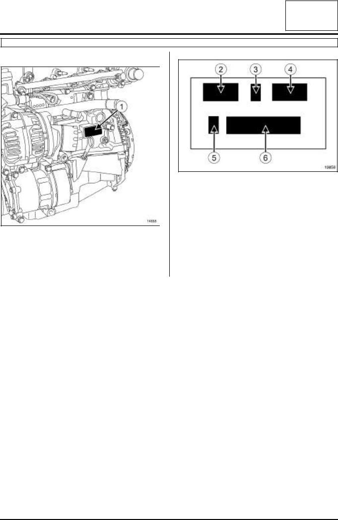
The engine can be identified by markings (1) located on the cylinder block.
Details of markings
19858
The markings consist of:
-(2) : the engine type,
-(3) : the engine approval letter,
-(4) : the engine suffix,
-(5) : the factory where the engine is fitted,
-(6) : the engine production number.
II - TABLE OF ENGINE SPECIFICATIONS
|
Engine |
Suffix |
|
C u b i c |
c a p a - |
Bore (mm) |
Stroke (mm) |
Compression ratio |
|
|
|
|
|
|
city(cc) |
|
|
|
|
|
|
|
|
|
|
|
|
|
|
|
|
|
700 |
|
|
|
|
|
|
|
|
|
|
|
|
|
|
|
|
|
|
|
710 |
|
|
|
|
|
|
|
|
|
|
|
|
|
|
|
|
|
|
|
711 |
|
|
|
|
|
|
|
|
|
|
|
|
|
|
|
|
|
|
|
712 |
|
|
|
|
|
|
|
|
|
|
|
|
|
|
|
|
|
|
|
713 |
|
|
|
|
|
|
|
|
|
|
|
|
|
|
|
|
|
|
|
714 |
|
|
|
|
|
|
|
|
|
|
|
|
|
|
|
|
|
K4J |
715 |
1390 |
|
79.5 |
70 |
10/1 |
||
|
|
|
|
|
|
|
|
|
|
|
|
|
730 |
|
|
|
|
|
|
|
|
|
|
|
|
|
|
|
|
|
|
|
732 |
|
|
|
|
|
|
|
|
|
|
|
|
|
|
|
|
|
|
|
740 |
|
|
|
|
|
|
|
|
|
|
|
|
|
|
|
|
|
|
|
750 |
|
|
|
|
|
|
|
|
|
|
|
|
|
|
|
|
|
|
|
770 |
|
|
|
|
|
|
|
|
|
|
|
|
|
|
|
|
|
|
|
780 |
|
|
|
|
|
|
|
|
|
|
|
|
|
|
|
|
10A-1

|
|
ENGINE AND CYLINDER BLOCK ASSEMBLY |
|
10A |
|||||||
|
|
|
|
|
|
Engine: Specifications |
|
|
|||
|
|
|
|
|
|
|
|
|
|
|
|
|
|
|
|
|
|
|
|
|
|
|
|
|
K4M |
|
|
|
|
|
|
|
|
|
|
|
|
|
|
|
|
|
|
|
|
|
|
|
Engine |
|
|
Suffix |
|
C u b i c |
c a p a - |
Bore (mm) |
Stroke (mm) |
Compression ratio |
|
|
|
|
|
|
|
city(cc) |
|
|
|
|
|
|
|
|
|
|
|
|
|
|
|
|
|
|
|
|
|
604c |
|
|
|
|
|
9.8/1 |
|
|
|
|
|
|
|
|
|
|
|
|
|
|
|
|
|
670 |
|
|
|
|
|
10/1 |
|
|
|
|
|
|
|
|
|
|
|
|
|
|
|
|
|
674 |
|
|
|
|
|
9.8/1 |
|
|
|
|
|
|
|
|
|
|
|
|
|
|
|
|
|
677 |
|
|
|
|
|
10/1 |
|
|
|
|
|
|
|
|
|
|
|
|
|
|
|
|
|
680 |
|
|
|
|
|
|
|
|
|
|
|
|
|
|
|
|
|
|
|
|
|
|
|
690 |
|
|
|
|
|
|
|
|
|
|
|
|
|
|
|
|
|
|
|
|
|
|
|
694b |
|
|
|
|
|
9.8/1 |
|
|
|
|
|
697 |
|
|
|
|
|
|
|
|
|
|
|
|
|
|
|
|
|
|
|
|
|
|
|
698c |
|
|
|
|
|
|
|
|
|
|
|
700 |
|
|
|
|
|
|
|
|
|
|
|
|
|
|
|
|
|
|
|
|
|
|
|
701 |
|
|
|
|
|
|
|
|
|
|
|
|
|
|
|
|
|
|
|
|
|
|
|
704a |
|
|
|
|
|
|
|
|
|
|
|
706 |
|
|
|
|
|
|
|
|
|
|
|
|
|
|
|
|
|
|
|
|
K4M |
|
|
707 |
|
1598 |
|
79.5 |
80.5 |
|
|
|
|
|
|
|
|
|
|
||||
|
|
|
708 |
|
|
10/1 |
|
||||
|
|
|
|
|
|
|
|
|
|
||
|
|
|
|
|
|
|
|
|
|
|
|
|
|
|
|
709 |
|
|
|
|
|
|
|
|
|
|
|
|
|
|
|
|
|
|
|
|
|
|
|
710 |
|
|
|
|
|
|
|
|
|
|
|
|
|
|
|
|
|
|
|
|
|
|
|
711 |
|
|
|
|
|
|
|
|
|
|
|
|
|
|
|
|
|
|
|
|
|
|
|
712a |
|
|
|
|
|
|
|
|
|
|
|
714a |
|
|
|
|
|
|
|
|
|
|
|
716 |
|
|
|
|
|
9.8/1 |
|
|
|
|
|
|
|
|
|
|
|
|
|
|
|
|
|
718a |
|
|
|
|
|
|
|
|
|
|
|
720 |
|
|
|
|
|
|
|
|
|
|
|
|
|
|
|
|
|
|
|
|
|
|
|
724a |
|
|
|
|
|
|
|
|
|
|
|
|
|
|
|
|
|
10/1 |
|
|
|
|
|
730 |
|
|
|
|
|
|
|
|
|
|
|
|
|
|
|
|
|
|
|
|
|
|
|
732 |
|
|
|
|
|
|
|
|
|
|
|
|
|
|
|
|
|
|
|
|
|
|
|
734 |
|
|
|
|
|
|
|
|
|
|
|
|
|
|
|
|
|
|
|
|
|
|
|
736 |
|
|
|
|
|
|
|
|
|
|
|
|
|
|
|
|
|
|
|
10A-2

|
|
ENGINE AND CYLINDER BLOCK ASSEMBLY |
|
10A |
|||||||
|
|
|
|
|
|
Engine: Specifications |
|
|
|||
|
|
|
|
|
|
|
|
|
|
|
|
|
|
|
|
|
|
|
|
|
|
|
|
|
K4M |
|
|
|
|
|
|
|
|
|
|
|
|
|
|
|
|
|
|
|
|
|
|
|
Engine |
|
|
Suffix |
|
C u b i c |
c a p a - |
Bore (mm) |
Stroke (mm) |
Compression ratio |
|
|
|
|
|
|
|
city(cc) |
|
|
|
|
|
|
|
|
|
|
|
|
|
|
|
|
|
|
|
|
|
740 |
|
|
|
|
|
|
|
|
|
|
|
|
|
|
|
|
|
|
|
|
|
|
|
742 |
|
|
|
|
|
|
|
|
|
|
|
|
|
|
|
|
|
|
|
|
|
|
|
743 |
|
|
|
|
|
|
|
|
|
|
|
|
|
|
|
|
|
|
|
|
|
|
|
744 |
|
|
|
|
|
|
|
|
|
|
|
|
|
|
|
|
|
|
|
|
|
|
|
745 |
|
|
|
|
|
|
|
|
|
|
|
|
|
|
|
|
|
|
|
|
|
|
|
746 |
|
|
|
|
|
|
|
|
|
|
|
|
|
|
|
|
|
|
|
|
|
|
|
748 |
|
|
|
|
|
|
|
|
|
|
|
|
|
|
|
|
|
10/1 |
|
|
|
|
|
750 |
|
|
|
|
|
|
|
|
|
|
|
|
|
|
|
|
|
|
|
|
|
|
|
|
|
|
|
|
|
|
|
|
|
|
|
752 |
|
|
|
|
|
|
|
|
|
|
|
|
|
|
|
|
|
|
|
|
|
|
|
753 |
|
|
|
|
|
|
|
|
|
|
|
|
|
|
|
|
|
|
|
|
|
|
|
754 |
|
|
|
|
|
|
|
|
|
|
|
|
|
|
|
|
|
|
|
|
|
|
|
760 |
|
|
|
|
|
|
|
|
|
|
|
|
|
|
|
|
|
|
|
|
|
|
|
761 |
|
|
|
|
|
|
|
|
K4M |
|
|
|
|
1598 |
|
79.5 |
80.5 |
|
|
|
|
|
764a |
|
|
|
|
||||
|
|
|
|
|
|
|
|
|
|
|
|
|
|
|
|
766 |
|
|
|
|
|
9.7/1 |
|
|
|
|
|
|
|
|
|
|
|
|
|
|
|
|
|
768b |
|
|
|
|
|
|
|
|
|
|
|
776 |
|
|
|
|
|
|
|
|
|
|
|
|
|
|
|
|
|
|
|
|
|
|
|
782 |
|
|
|
|
|
|
|
|
|
|
|
|
|
|
|
|
|
10/1 |
|
|
|
|
|
788 |
|
|
|
|
|
|
|
|
|
|
|
|
|
|
|
|
|
|
|
|
|
|
|
790 |
|
|
|
|
|
|
|
|
|
|
|
|
|
|
|
|
|
|
|
|
|
|
|
791 |
|
|
|
|
|
|
|
|
|
|
|
|
|
|
|
|
|
|
|
|
|
|
|
794 |
|
|
|
|
|
|
|
|
|
|
|
|
|
|
|
|
|
|
|
|
|
|
|
800 |
|
|
|
|
|
9.8/1 |
|
|
|
|
|
|
|
|
|
|
|
|
|
|
|
|
|
801 |
|
|
|
|
|
|
|
|
|
|
|
|
|
|
|
|
|
|
|
|
|
|
|
|
|
|
|
|
|
|
|
|
|
|
|
802 |
|
|
|
|
|
10/1 |
|
|
|
|
|
|
|
|
|
|
|
|
|
|
|
|
|
804 |
|
|
|
|
|
9.8/1 |
|
|
|
|
|
|
|
|
|
|
|
|
|
10A-3
|
|
ENGINE AND CYLINDER BLOCK ASSEMBLY |
|
10A |
||||||||
|
|
|
|
|
|
|
Engine: Specifications |
|
|
|||
|
|
|
|
|
|
|
|
|
|
|
|
|
|
|
|
|
|
|
|
|
|
|
|
|
|
|
K4M |
|
|
|
|
|
|
|
|
|
|
|
|
|
|
|
|
|
|
|
|
|
|
||
|
Engine |
|
|
Suffix |
|
C u b i c |
c a p a - |
Bore (mm) |
Stroke (mm) |
Compression ratio |
||
|
|
|
|
|
|
|
city(cc) |
|
|
|
|
|
|
|
|
|
|
|
|
|
|
|
|
|
|
|
|
|
|
812 |
|
|
|
|
|
|
|
|
|
|
|
|
|
|
|
|
|
|
|
9.7/1 |
|
|
|
|
|
813 |
|
|
|
|
|
|
|
|
|
|
|
|
|
|
|
|
|
|
|
|
|
|
|
|
|
824 |
|
|
|
|
|
|
|
|
|
|
|
|
|
|
|
|
|
|
|
|
|
|
|
|
|
830 |
|
|
|
|
|
|
|
|
|
|
|
|
|
|
|
|
|
|
|
|
|
|
|
|
|
831 |
|
|
|
|
|
|
9.8/1 |
|
|
|
|
|
|
|
|
|
|
|
|
|
|
|
|
|
|
834 |
|
|
|
|
|
|
|
|
|
|
|
|
|
|
|
|
|
|
|
|
|
|
K4M |
|
|
|
|
|
1598 |
|
79.5 |
80.5 |
|
|
|
|
|
848 |
|
|
|
|
|
||||
|
|
|
|
|
|
|
|
|
|
|
|
|
|
|
|
|
|
|
|
|
|
|
|
|
|
|
|
|
|
854 |
|
|
|
|
|
|
11/1 |
|
|
|
|
|
|
|
|
|
|
|
|
|
|
|
|
|
|
856 |
b |
|
|
|
|
|
9.8/1 |
|
|
|
|
|
|
|
|
|
|
|
|
|
|
|
|
|
|
|
|
|
|
|
|
|
|
|
|
|
|
|
858 |
|
|
|
|
|
|
9.7/1 |
|
|
|
|
|
|
|
|
|
|
|
|
|
|
|
|
|
|
862 |
|
|
|
|
|
|
11/1 |
|
|
|
|
|
|
|
|
|
|
|
|
|
|
|
|
|
|
866b |
|
|
|
|
|
9.7/1 |
|
|
|
|
|
|
|
|
|
|
|
|
|
|
|
a:Engine running on liquefied petroleum gas
b:Engine running on a mixture of ethanol/petrol
c:Engine running on compressed natural gas
10A-4
ENGINE AND CYLINDER BLOCK ASSEMBLY |
10A |
Engine: Specifications |
F9Q
I - ENGINE IDENTIFICATION
124959
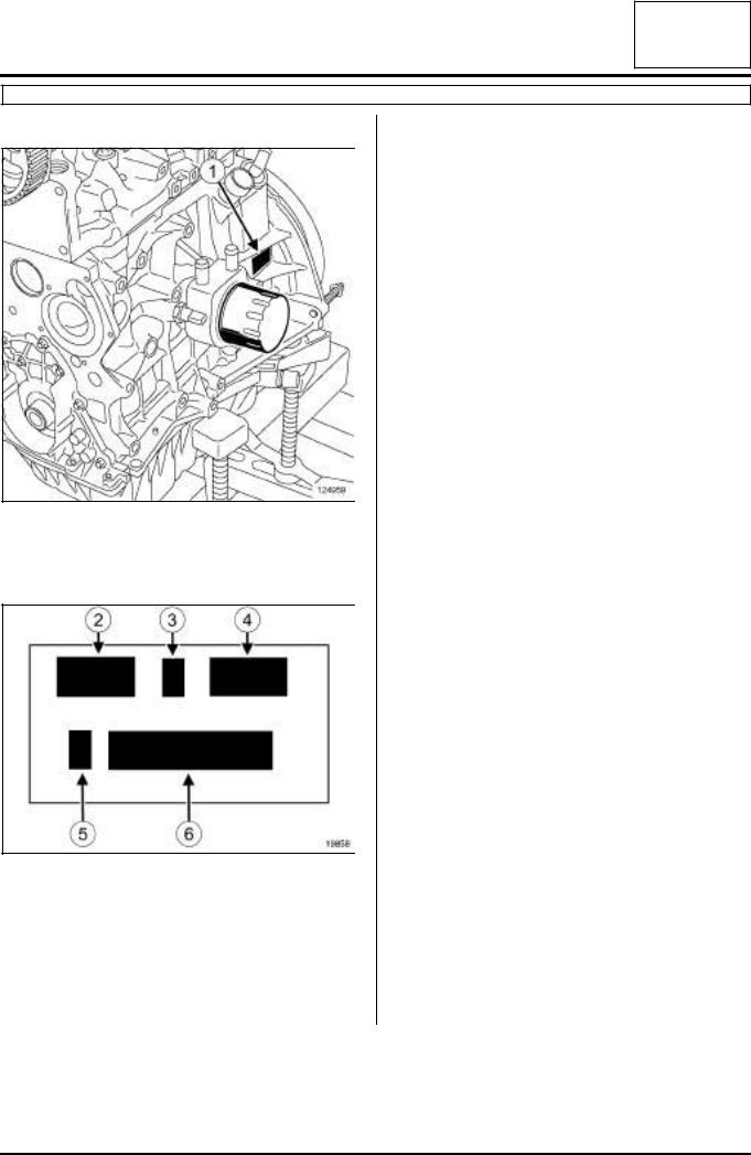
The engine can be identified by markings (1) located on the cylinder block.
Details of markings
19858
The markings consist of:
-(2) : the engine type,
-(3) : the engine approval letter,
-(4) : the engine suffix,
-(5) : the factory where the engine is fitted,
-(6) : the engine production number.
10A-5
ENGINE AND CYLINDER BLOCK ASSEMBLY |
10A |
Engine: Specifications |
F9Q
II - TABLE OF ENGINE SPECIFICATIONS
|
Engine type |
Engine suffix |
|
Cubic capa- |
Bore (mm) |
Stroke (mm) |
Compres- |
|
|
|
|
|
|
city(cc) |
|
|
|
sion ratio |
|
|
|
|
|
|
|
|
|
|
|
|
|
200 |
|
|
|
|
|
|
|
|
|
|
|
|
|
|
|
|
|
|
|
204 |
|
|
|
|
|
18.4:1 |
|
|
|
|
|
|
|
|
|
|
|
|
|
260 |
|
|
|
|
|
|
|
|
|
|
|
|
|
|
|
|
|
|
|
264 |
|
|
|
|
|
16.9/1 |
|
|
|
|
|
|
|
|
|
|
|
|
|
650 |
|
|
|
|
|
|
|
|
|
|
|
|
|
|
|
|
|
|
|
664 |
|
|
|
|
|
18.4:1 |
|
|
|
|
|
|
|
|
|
|
|
|
|
670 |
|
|
|
|
|
|
|
|
|
|
|
|
|
|
|
|
|
|
|
|
|
|
|
|
|
|
|
|
|
674 |
|
|
|
|
|
|
|
|
|
|
|
|
|
|
|
|
|
|
|
718 |
|
|
|
|
|
19:1 |
|
|
|
|
|
|
|
|
|
|
|
|
|
732 |
|
|
|
|
|
18.4:1 |
|
|
|
|
|
|
|
|
|
|
|
|
|
733 |
|
|
|
|
|
|
|
|
|
|
|
|
|
|
|
|
|
|
|
|
|
|
|
|
|
|
|
|
|
738 |
|
|
|
|
|
|
|
|
|
|
|
|
|
|
|
|
|
|
|
740 |
|
|
|
|
|
19:1 |
|
|
|
|
|
|
|
|
|
|
|
|
F9Q |
748 |
|
1870 |
80 |
93 |
|
|
|
|
|
|
|
|
|
||||
|
750 |
|
|
|
|
||||
|
|
|
|
|
|
|
|
|
|
|
|
|
|
|
|
|
|
|
|
|
|
752 |
|
|
|
|
|
18.4:1 |
|
|
|
|
|
|
|
|
|
|
|
|
|
754 |
|
|
|
|
|
|
|
|
|
|
|
|
|
|
|
|
|
|
|
758 |
|
|
|
|
|
16.9/1 |
|
|
|
|
|
|
|
|
|
|
|
|
|
759 |
|
|
|
|
|
|
|
|
|
|
|
|
|
|
|
|
|
|
|
|
|
|
|
|
|
|
|
|
|
760 |
|
|
|
|
|
|
|
|
|
|
|
|
|
|
|
|
|
|
|
762 |
|
|
|
|
|
|
|
|
|
|
|
|
|
|
|
|
|
|
|
772 |
|
|
|
|
|
|
|
|
|
|
|
|
|
|
|
|
|
|
|
774 |
|
|
|
|
|
18.4:1 |
|
|
|
|
|
|
|
|
|
|
|
|
|
790 |
|
|
|
|
|
|
|
|
|
|
|
|
|
|
|
|
|
|
|
796 |
|
|
|
|
|
|
|
|
|
|
|
|
|
|
|
|
|
|
|
800 |
|
|
|
|
|
|
|
|
|
|
|
|
|
|
|
|
|
|
|
803 |
|
|
|
|
|
16.9/1 |
|
|
|
|
|
|
|
|
|
|
|
|
|
804 |
|
|
|
|
|
|
|
|
|
|
|
|
|
|
|
|
|
|
|
|
|
|
|
|
|
|
|
|
|
|
|
|
|
|
|
|
|
10A-6

ENGINE AND CYLINDER BLOCK ASSEMBLY |
10A |
Engine: Specifications |
F9Q
Engine type |
Engine suffix |
Cubic capa- |
Bore (mm) |
Stroke (mm) |
Compres- |
|
|
|
|
city(cc) |
|
|
|
sion ratio |
|
|
|
|
|
|
|
|
|
|
808 |
|
|
|
|
|
|
|
|
|
|
|
|
18.4:1 |
|
|
812 |
|
|
|
|
||
|
|
|
|
|
|
|
|
|
|
|
|
|
|
|
|
|
816 |
|
|
|
|
16.9/1 |
|
|
|
|
|
|
|
|
|
F9Q |
818 |
1870 |
80 |
93 |
|
18.4:1 |
|
|
|
|
|
|
|
|
|
|
820 |
|
|
|
|
||
|
|
|
|
|
|
|
|
|
|
|
|
|
|
|
|
|
870 |
|
|
|
|
16.9/1 |
|
|
|
|
|
|
|
|
|
|
872 |
|
|
|
|
||
|
|
|
|
|
|
|
|
|
|
|
|
|
|
|
|
10A-7
ENGINE AND CYLINDER BLOCK ASSEMBLY |
10A |
Engine: Specifications |
M9R
I - ENGINE IDENTIFICATION
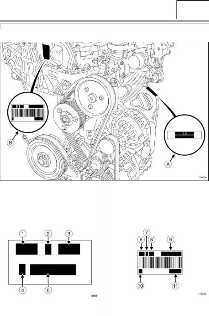
Engine identification is located:
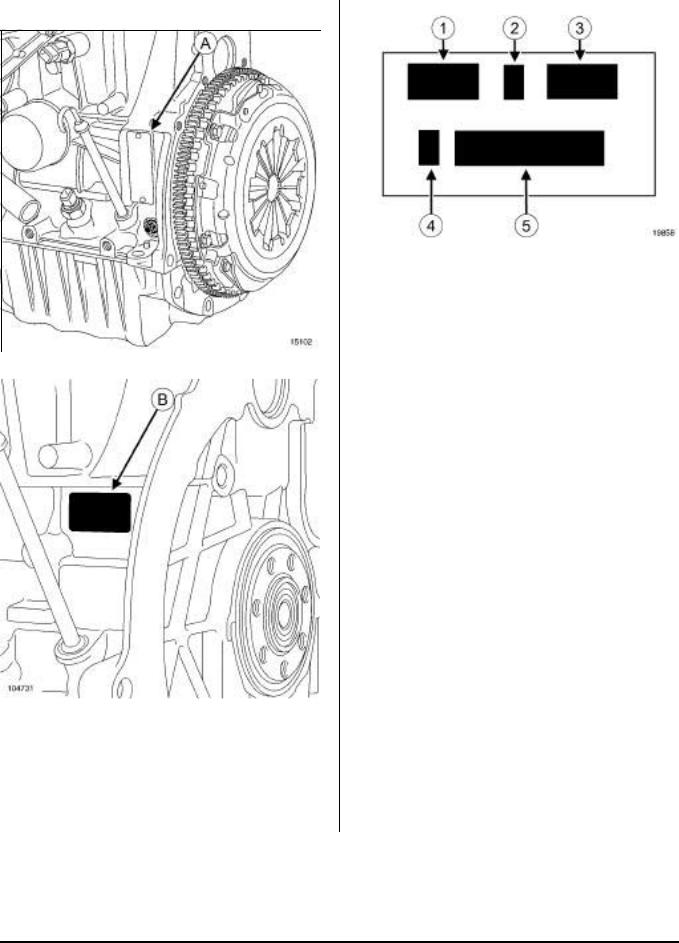
-on the cylinder block, by an etching below the exhaust gas cooler, next to the starter (A) ,
-on the timing cover, by a label affixed behind the engine mounting (B) .
Detail of the marking (A):
114834
-(2) the engine approval code,
-(3) the engine suffix,
-(4) the factory where the engine was fitted,
-(5) the engine serial number.
Detail of the marking (B):
|
|
|
|
|
|
|
|
|
|
114833 |
|
19858 |
|||
The markings include: |
|
The markings include: |
|
- (1) the engine type, |
|
- (6) the engine type, |
|
|
|
|
|
10A-8

ENGINE AND CYLINDER BLOCK ASSEMBLY |
10A |
Engine: Specifications |
M9R
-(7) the engine approval code,
-(8) the engine suffix,
-(9) the assembled engine part number,
-(10) the factory where the engine was fitted,
-(11) the engine serial number.
10A-9

ENGINE AND CYLINDER BLOCK ASSEMBLY |
10A |
Engine: Specifications |
M9R
II - TABLE OF ENGINE SPECIFICATIONS
10A-10

|
|
ENGINE AND CYLINDER BLOCK ASSEMBLY |
|
10A |
|||||
|
|
|
Engine: Specifications |
|
|
||||
|
|
|
|
|
|
|
|
|
|
|
|
|
|
|
|
|
|
|
|
|
M9R |
|
|
|
|
|
|
|
|
|
|
|
|
|
|
|
|
|
|
|
|
Engine type |
Engine suf- |
Cubic capa- |
Bore (mm) |
Stroke (mm) |
Compres- |
|
|
|
|
|
fix |
city (cc) |
|
|
sion ratio |
|
|
|
|
|
|
|
|
|
|
|
|
|
|
|
700 |
|
|
|
|
|
|
|
|
|
|
|
|
|
|
|
|
|
|
|
721 |
|
|
|
|
|
|
|
|
|
|
|
|
|
|
|
|
|
|
|
722 |
|
|
|
|
|
|
|
|
|
|
|
|
|
|
|
|
|
|
|
724 |
|
|
|
|
|
|
|
|
|
|
|
|
|
|
|
|
|
|
|
740 |
|
|
|
|
|
|
|
|
|
|
|
|
|
|
|
|
|
|
|
742 |
|
|
|
|
|
|
|
|
|
|
|
|
|
|
|
|
|
|
|
744 |
|
|
|
|
|
|
|
|
|
|
|
|
|
|
|
|
|
|
|
746 |
|
|
|
|
|
|
|
|
|
|
|
|
|
|
|
|
|
|
|
748 |
|
|
|
|
|
|
|
|
|
|
|
|
|
|
|
|
|
|
|
754 |
|
|
|
|
|
|
|
|
|
|
|
|
|
|
|
|
|
|
|
760 |
|
|
|
|
|
|
|
|
|
|
|
|
|
|
|
|
|
|
|
761 |
|
|
|
|
|
|
|
|
|
|
|
|
|
|
|
|
|
|
|
762 |
|
|
|
|
|
|
|
|
|
|
|
|
|
|
|
|
|
|
|
763 |
|
|
|
|
|
|
|
|
|
|
|
|
|
|
|
|
|
|
|
780 |
|
|
|
|
|
|
|
|
|
|
|
|
|
|
|
|
|
|
|
782 |
|
|
|
|
|
|
|
|
|
|
|
|
|
|
|
|
|
|
M9R |
784 |
1995 |
84 |
90 |
15.6 / 1 |
|
|
|
|
|
|
|
|
|
|
|
|
|
|
|
786 |
|
|
|
|
|
|
|
|
|
|
|
|
|
|
|
|
|
|
|
788 |
|
|
|
|
|
|
|
|
|
|
|
|
|
|
|
|
|
|
|
800 |
|
|
|
|
|
|
|
|
|
|
|
|
|
|
|
|
|
|
|
802 |
|
|
|
|
|
|
|
|
|
|
|
|
|
|
|
|
|
|
|
803 |
|
|
|
|
|
|
|
|
|
|
|
|
|
|
|
|
|
|
|
805 |
|
|
|
|
|
|
|
|
|
|
|
|
|
|
|
|
|
|
|
809 |
|
|
|
|
|
|
|
|
|
|
|
|
|
|
|
|
|
|
|
812 |
|
|
|
|
|
|
|
|
|
|
|
|
|
|
|
|
|
|
|
816 |
|
|
|
|
|
|
|
|
|
|
|
|
|
|
|
|
|
|
|
830 |
|
|
|
|
|
|
|
|
|
|
|
|
|
|
|
|
|
|
|
832 |
|
|
|
|
|
|
|
|
|
|
|
|
|
|
|
|
|
|
|
833 |
|
|
|
|
|
|
|
|
|
|
|
|
|
|
|
|
|
|
|
834 |
|
|
|
|
|
|
|
|
|
|
|
|
|
|
|
|
|
|
|
835 |
|
|
|
|
|
|
|
|
|
|
|
|
|
|
|
|
10A-11
|
ENGINE AND CYLINDER BLOCK ASSEMBLY |
10A |
|
|
Engine: Specifications |
||
|
|
|
|
|
|
|
|
|
F4P or F4R |
|
|
I - ENGINE IDENTIFICATION |
Details of markings |
|
|
|
|
|
|
|
|
|
|
19858
|
The markings include: |
|
|
- |
(1) : the engine type, |
|
- |
(2) : the engine approval letter, |
|
- |
(3) : the engine suffix, |
|
|
|
15102 |
- |
(4) : the factory where the engine is fitted, |
|
||
|
- |
(5) : the engine production number. |
|
||
|
|
|
104731
The engine identification is located on the cylinder block, above the dipstick.
It is either on a riveted plate or engraved on the cylinder block.
The markings may be written vertically (A) or horizontally (B) .
10A-12

ENGINE AND CYLINDER BLOCK ASSEMBLY |
10A |
Engine: Specifications |
F4P or F4R
II - TABLE OF ENGINE SPECIFICATIONS
|
Engine type |
Engine suffix |
Cubic capa- |
Bore (mm) |
Stroke (mm) |
Compression |
|
|
|
|
|
city(cc) |
|
|
ratio |
|
|
|
|
|
|
|
|
|
|
|
720 |
|
|
|
|
|
|
|
|
|
|
|
|
|
|
|
722 |
|
|
|
|
|
|
|
|
|
|
|
|
|
|
|
760 |
|
|
|
|
|
|
|
|
|
|
|
|
|
|
|
770 |
|
|
|
|
|
|
|
|
1783 |
82.7 |
83 |
9.8/1 |
|
F4P |
771 |
|||||
|
|
|
|
|
|
|
|
|
|
|
772 |
|
|
|
|
|
|
|
|
|
|
|
|
|
|
|
773 |
|
|
|
|
|
|
|
|
|
|
|
|
|
|
|
774 |
|
|
|
|
|
|
|
|
|
|
|
|
|
|
|
775 |
|
|
|
|
|
|
|
|
|
|
|
|
10A-13
|
ENGINE AND CYLINDER BLOCK ASSEMBLY |
10A |
||||||
|
|
|
Engine: Specifications |
|
|
|||
|
|
|
|
|
|
|
|
|
|
|
|
|
|
|
|
|
|
|
F4P or F4R |
|
|
|
|
|
|
|
|
|
|
|
|
|
|
|
|
|
Engine type |
Engine suffix |
Cubic capa- |
Bore (mm) |
Stroke (mm) |
Compression |
||
|
|
|
|
city(cc) |
|
|
|
ratio |
|
|
|
|
|
|
|
|
|
|
|
|
700 |
|
|
|
|
|
|
|
|
|
|
|
|
|
|
|
|
|
701 |
|
|
|
|
|
|
|
|
|
|
|
|
|
|
|
|
|
712 |
|
|
|
|
|
|
|
|
|
|
|
|
|
9.8/1 |
|
|
|
713 |
|
|
|
|
|
|
|
|
|
|
|
|
|
|
|
|
|
714 |
|
|
|
|
|
|
|
|
|
|
|
|
|
|
|
|
|
715 |
|
|
|
|
|
|
|
|
|
|
|
|
|
|
|
|
|
720 |
|
|
|
|
|
|
|
|
|
|
|
|
|
|
|
|
|
730 |
|
|
|
|
11.2/1 |
|
|
|
|
|
|
|
|
|
|
|
|
732 |
|
|
|
|
|
|
|
|
|
|
|
|
|
11/1 |
|
F4R |
|
736 |
1998 |
82.7 |
93 |
|
|
|
|
|
|
|
||||
|
|
738 |
|
|
||||
|
|
|
|
|
|
|
|
|
|
|
|
|
|
|
|
|
|
|
|
|
740 |
|
|
|
|
|
|
|
|
|
|
|
|
|
|
|
|
|
741 |
|
|
|
|
|
|
|
|
|
|
|
|
|
9.8/1 |
|
|
|
744 |
|
|
|
|
|
|
|
|
|
|
|
|
|
|
|
|
|
746 |
|
|
|
|
|
|
|
|
|
|
|
|
|
|
|
|
|
747 |
|
|
|
|
|
|
|
|
|
|
|
|
|
|
|
|
|
760 |
|
|
|
|
|
|
|
|
|
|
|
|
|
|
|
|
|
761 |
|
|
|
|
9.5/1 |
|
|
|
|
|
|
|
|
|
|
|
|
762 |
|
|
|
|
|
|
|
|
|
|
|
|
|
|
|
|
|
|
|
|
|
|
|
|
|
|
763 |
|
|
|
|
|
|
|
|
|
|
|
|
|
|
10A-14

|
ENGINE AND CYLINDER BLOCK ASSEMBLY |
10A |
||||||
|
|
|
Engine: Specifications |
|
|
|||
|
|
|
|
|
|
|
|
|
|
|
|
|
|
|
|
|
|
|
F4P or F4R |
|
|
|
|
|
|
|
|
|
|
|
|
|
|
|
|
|
Engine type |
Engine suffix |
Cubic capa- |
Bore (mm) |
Stroke (mm) |
Compression |
||
|
|
|
|
city(cc) |
|
|
|
ratio |
|
|
|
|
|
|
|
|
|
|
|
|
764 |
|
|
|
|
|
|
|
|
|
|
|
|
|
|
|
|
|
765 |
|
|
|
|
9.5/1 |
|
|
|
|
|
|
|
|
|
|
|
|
766 |
|
|
|
|
|
|
|
|
|
|
|
|
|
|
|
|
|
|
|
|
|
|
|
|
|
|
767 |
|
|
|
|
|
|
|
|
|
|
|
|
|
|
|
|
|
770 |
|
|
|
|
9.8/1 |
|
|
|
|
|
|
|
|
|
|
|
|
771 |
|
|
|
|
|
|
|
|
|
|
|
|
|
|
|
|
|
|
|
|
|
|
|
|
|
|
774 |
|
|
|
|
9/1 |
|
|
|
|
|
|
|
|
|
|
|
|
776 |
|
|
|
|
9.5/1 |
|
|
|
|
|
|
|
|
|
|
|
|
780 |
|
|
|
|
9.8/1 |
|
|
|
|
|
|
|
|
|
|
|
|
784 |
|
|
|
|
9/1 |
|
|
|
|
|
|
|
|
|
|
|
|
786 |
|
|
|
|
9.5/1 |
|
|
|
|
|
|
|
|
|
|
|
|
787 |
|
|
|
|
|
|
|
|
|
|
|
|
|
|
|
|
|
|
|
|
|
|
|
|
|
|
790 |
|
|
|
|
9.8/1 |
|
|
|
|
|
|
|
|
|
|
|
|
792 |
|
|
|
|
|
|
|
|
|
|
|
|
|
|
|
|
|
|
1998 |
82.7 |
93 |
|
|
|
F4R |
794 |
|
|
||||
|
|
|
|
|
|
|
|
|
|
|
|
795 |
|
|
|
|
9.5/1 |
|
|
|
|
|
|
|
|
|
|
|
|
796 |
|
|
|
|
|
|
|
|
|
|
|
|
|
|
|
|
|
|
|
|
|
|
|
|
|
|
797 |
|
|
|
|
|
|
|
|
|
|
|
|
|
|
|
|
|
800 |
|
|
|
|
9/1 |
|
|
|
|
|
|
|
|
|
|
|
|
811 |
|
|
|
|
9.5/1 |
|
|
|
|
|
|
|
|
|
|
|
|
813 |
|
|
|
|
|
|
|
|
|
|
|
|
|
|
|
|
|
|
|
|
|
|
|
|
|
|
820 |
|
|
|
|
9.8/1 |
|
|
|
|
|
|
|
|
|
|
|
|
830 |
|
|
|
|
11.5/1 |
|
|
|
|
|
|
|
|
|
|
|
|
867 |
|
|
|
|
|
|
|
|
|
|
|
|
|
|
|
|
|
870 |
|
|
|
|
|
|
|
|
|
|
|
|
|
|
|
|
|
886 |
|
|
|
|
9.5/1 |
|
|
|
|
|
|
|
|
|
|
|
|
887 |
|
|
|
|
|
|
|
|
|
|
|
|
|
|
|
|
|
|
|
|
|
|
|
|
|
|
896 |
|
|
|
|
|
|
|
|
|
|
|
|
|
|
|
|
|
897 |
|
|
|
|
|
|
|
|
|
|
|
|
|
|
10A-15
|
ENGINE AND CYLINDER BLOCK ASSEMBLY |
10A |
|||
|
Crankshaft seal at timing end Removal - Refitting |
||||
|
|
|
|
|
|
|
|
|
|
|
|
|
M9R, and DOCUMENT PHASE 2 |
|
|
|
|
|
|
|
REFITTING |
|
|
|
|
|
|
|
|
|
Tightening torquesm |
|
a |
|
|
|
|
|
|
|
|
|
|
|
|
|
|
|
crankshaft timing end |
47 Nm |
|
WARNING |
|
|
sealing ring |
|
|
The joint faces must be clean, dry and free from |
|
|
|
|
|
grease (avoid finger marks). |
|
|
|
|
|
||
|
|
|
|
|
|
REMOVAL
aPosition the vehicle on a two-post lift (see 02A, Lifting equipment, Vehicle, Towing and lifting).
aRemove:
-the front right-hand wheel (see 35A, Wheels and tyres, Wheel: Removal - Refitting),
-the front right-hand wheel arch liner (see MR 396
Bodywork, 55A, Exterior protection, Wheel arch liner, Removal - Refitting),
-the accessories belt (see 11A, Top and front of engine, Accessories belt: Removal - Refitting, page 11A-4) ,
-the crankshaft accessories pulley (see 11A, Top and front of engine, Crankshaft accessories pulley: Removal - Refitting, page 11A-16) .
113656
113659
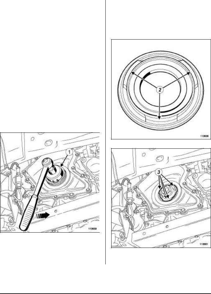
aRemove the crankshaft sealing ring using the (1) supplied in the spare parts kit for the new gasket.
113661
a Position the sealing ring notches (2) opposite the notches (3) in the timing cover.
10A-16
ENGINE AND CYLINDER BLOCK ASSEMBLY |
10A |
Crankshaft seal at timing end Removal - Refitting |
M9R, and DOCUMENT PHASE 2
- the accessories belt (see 11A, Top and front of engine, Accessories belt: Removal - Refitting, page 11A-4) ,
- the front right-hand wheel arch liner (see MR 396
Bodywork, 55A, Exterior protection, Wheel arch liner, Removal - Refitting),
- the front right-hand wheel (see 35A, Wheels and tyres, Wheel: Removal - Refitting).
113662
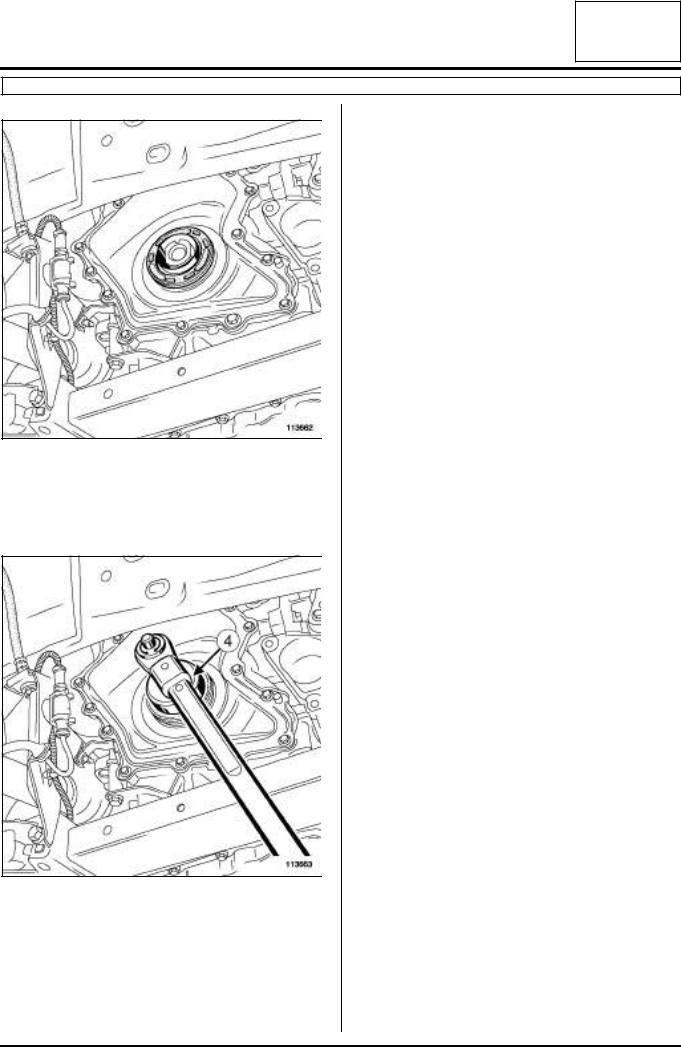
aEngage the sealing ring notches in the timing cover notches.
aTighten the sealing ring by hand using the tool supplied in the new gasket spare parts kit.
113663
aUsing the (4) supplied in the new gasket spare parts kit, tighten to torque the crankshaft timing end sealing ring (47 Nm).
aRefit:
-the crankshaft accessories pulley (see 11A, Top and front of engine, Crankshaft accessories pulley: Removal - Refitting, page 11A-16) ,
10A-17
ENGINE AND CYLINDER BLOCK ASSEMBLY |
10A |
Crankshaft seal at timing end Removal - Refitting |
F4R, and 714 or 715 or 784 or 786 or 787, and DOCUMENT PHASE 2
Tightening torquesm
crankshaft accessories |
40 Nm + 110˚ ± |
pulley mounting bolt |
10˚ |
|
|
right-hand side member |
44 Nm |
tie rod mounting bolts |
|
REMOVAL
I - REMOVAL PREPARATION OPERATION
aPosition the vehicle on a two-post lift (see 02A, Lifting equipment, Two-post lift: Safety).
aRemove:
-the front right-hand wheel (see 35A, Wheels and tyres, Wheel: Removal - Refitting),
-the front right-hand wheel arch liner (see MR396
Bodywork, 55A, Exterior protection, Wheel arch liners Removal - Refitting),
-the accessories belt (see 11A, Top and front of engine, Accessories belt: Removal - Refitting, page 11A-4) .
16152
aRemove:
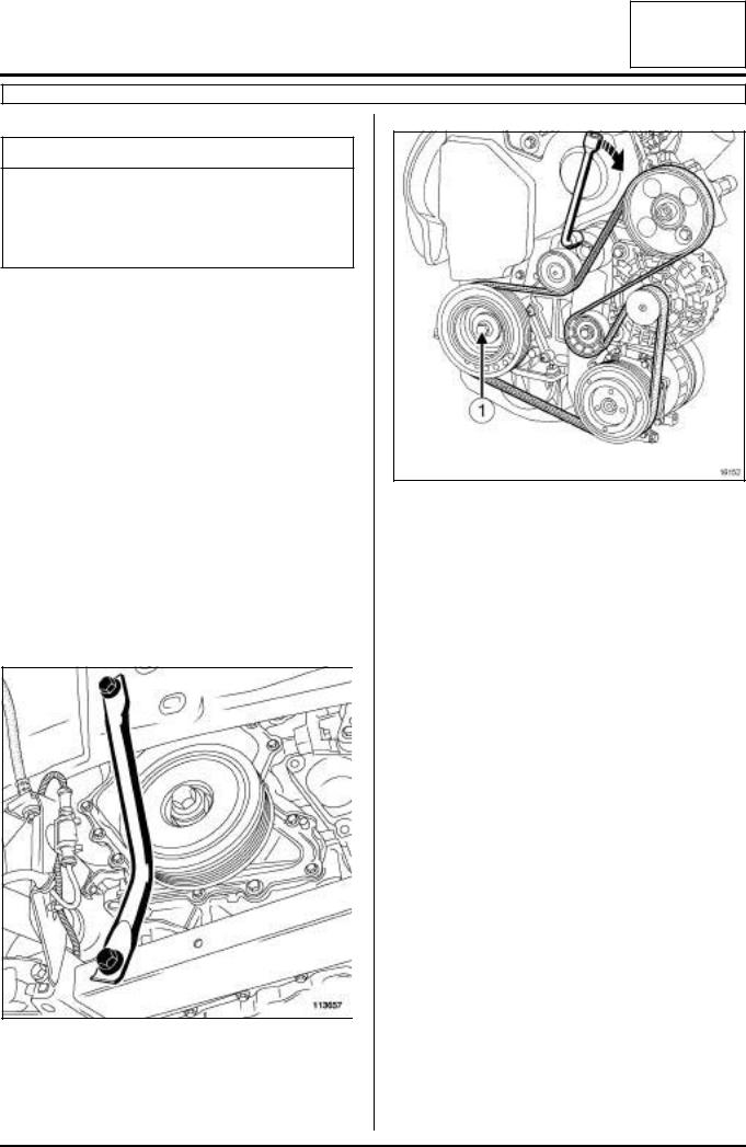
-the crankshaft accessories pulley mounting bolt (1)
,
-the crankshaft accessories pulley.
aRemove the timing belt (see 11A, Top and front of engine, Timing belt: Removal - Refitting, page 11A-26) .
113657
aRemove:
-the right-hand side member tie-rod mounting bolts,
-the right-hand side member tie-rod.
10A-18
ENGINE AND CYLINDER BLOCK ASSEMBLY |
10A |
Crankshaft seal at timing end Removal - Refitting |
F4R, and 714 or 715 or 784 or 786 or 787, and DOCUMENT PHASE 2
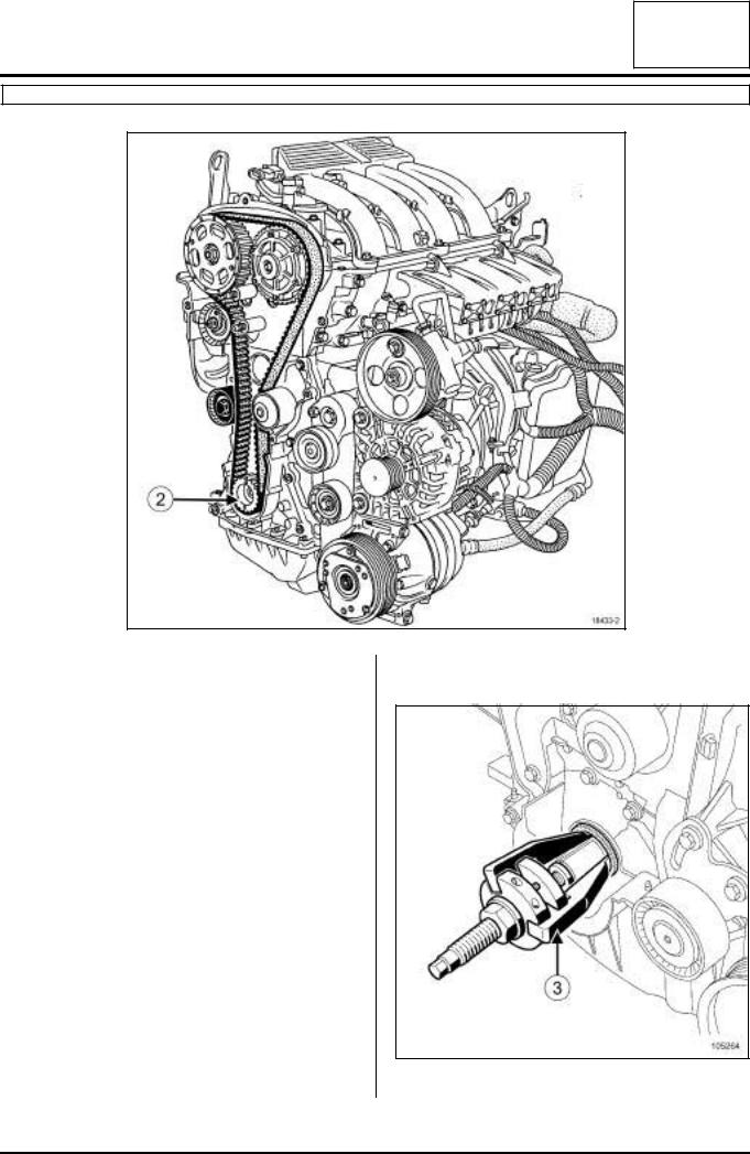
a Remove the crankshaft timing sprocket (2) .
18433-2
II - OPERATION FOR REMOVAL OF PART CONCERNED
105264
a Remove the crankshaft seal using the (3) .
10A-19

ENGINE AND CYLINDER BLOCK ASSEMBLY |
10A |
Crankshaft seal at timing end Removal - Refitting |
F4R, and 714 or 715 or 784 or 786 or 787, and DOCUMENT PHASE 2
REFITTING
I - REFITTING PREPARATION OPERATION
a
WARNING
The gasket faces must be clean, dry and free from grease (avoid finger marks).
II - REFITTING OPERATION FOR PART
CONCERNED
a Fit the new timing end crankshaft seal.
III - FINAL OPERATION
aRefit:
-the crankshaft timing sprocket,
-the timing belt (see 11A, Top and front of engine, Timing belt: Removal - Refitting, page 11A-26) ,
-the crankshaft accessories pulley.
aTighten to torque the crankshaft accessories pulley mounting bolt (40 Nm + 110˚ ± 10˚).
aRefit the right-hand side member tie-rod.
aTighten to torque the right-hand side member tie rod mounting bolts (44 Nm).
aRefit:
-the accessories belt (see 11A, Top and front of engine, Accessories belt: Removal - Refitting, page 11A-4) ,
-the front right-hand wheel arch liner (see MR 396
Bodywork, 55A, Exterior protection, Wheel arch liners Removal - Refitting),
-the front right-hand wheel (see 35A, Wheels and tyres, Wheel: Removal - Refitting).
10A-20

ENGINE AND CYLINDER BLOCK ASSEMBLY |
10A |
Crankshaft seal at timing end Removal - Refitting |
L7X, and 733, and DOCUMENT PHASE 2
aTo follow the removal - refitting procedure for the timing end crankshaft seal, see 10A, Engine and peripherals, Oil pump: Removal - Refitting.
10A-21
ENGINE AND CYLINDER BLOCK ASSEMBLY |
10A |
Crankshaft seal at timing end Removal - Refitting |
G9T, and DOCUMENT PHASE 2
|
|
Essential special tooling |
|
|
|
|
Mot. 1560 |
Tool for fitting crankshaft seal |
|
|
on timing end. |
|
|
|
|
Mot. 1628 |
Set of 3 sleeves for fitting |
|
|
elastomer seals. |
|
|
|
REMOVAL
I - REMOVAL PREPARATION OPERATION
aPosition the vehicle on a two-post lift (see 02A, Lifting equipment, Vehicle, Towing and lifting).
aDisconnect the battery (see 80A, Battery, Battery: Removal - Refitting).
aRemove:
-the engine undertray,
-the front right-hand wheel (see 35A, Wheels and tyres, Wheel: Removal - Refitting),
-the accessories belt (see 11A, Top and front of engine, Accessories belt: Removal - Refitting, page 11A-4) ,
-the crankshaft accessories pulley (see 11A, Top and front of engine, Crankshaft accessories pulley: Removal - Refitting, page 11A-16) .
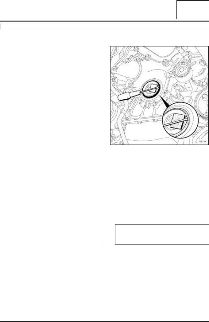
II - REMOVAL OPERATION FOR PART CONCERNED
118744
aRemove the crankshaft seal using a medium screwdriver and a wooden block to avoid damaging the crankshaft mating face.
REFITTING
I - REFITTING PREPARATION OPERATION
a Clean the seal mating faces using a clean cloth.
II - REFITTING OPERATION FOR PART CONCERNED
a
WARNING
The joint faces must be clean, dry and free from grease (avoid finger marks).
10A-22

ENGINE AND CYLINDER BLOCK ASSEMBLY |
10A |
Crankshaft seal at timing end Removal - Refitting |
G9T, and DOCUMENT PHASE 2
18690
aFit the threaded rod (1) of the (Mot. 1560) into the crankshaft.
18690-2
aFit the protector marked C of the (Mot. 1628), fitted with the new crankshaft seal, onto the crankshaft.
Note:
Never oil before fitting; the parts must stay clean and dry.
18690-3
aFit:
-the cover (2) of the (Mot. 1560),
-the nut (3) of the (Mot. 1560).
aPosition the thread hole (4) towards the outside of the engine.
18690-4
aScrew on the nut until the cover makes contact with the timing cover.
aRemove: - the nut,
10A-23
Loading...