


 Loading...
0 General vehicle information
01A VEHICLE MECHANICAL SPECIFICATIONS
01C VEHICLE BODYWORK SPECIFICATIONS
01D MECHANICAL INTRODUCTION
02A LIFTING EQUIPMENT
03B COLLISION
04B CONSUMABLES - PRODUCTS
04E PAINT
X38, and B32 or L38
OCTOBER 2009 |
EDITION ANGLAISE |
"The repair procedures given by the manufacturer in this document are based on the technical specifications current when it was prepared.
The procedures may be modified as a result of changes introduced by the manufacturer in
the production of the various component units and accessories from which the vehicles are constructed".
All rights reserved by Renault.
Copying or translating, in part or in full, of this document or use of the service part reference numbering system is forbidden without the prior written authority of Renault.
© Renault s.a.s 2007

FLUENCE - MEGANE GENERATION -
Section 0
Contents
|
|
Pages |
|
|
|
|
|
|
|
|
|
01A |
VEHICLE MECHANICAL SPECIFICATIONS |
04E |
PAINT |
|
|
|
Vehicle: Specifications |
01A-1 |
|
Anti-corrosion protection |
|
|
|
|
|||
|
|
|
|
product: Description |
04E-1 |
|
|
|
|
Colour code: Specifications |
04E-5 |
01C |
VEHICLE BODYWORK SPECIFICATIONS |
|
|
|
|
|
Vehicle panel gaps: |
|
|
|
|
|
|
|
|
|
|
|
Adjustment value |
01C-1 |
|
|
|
01D MECHANICAL INTRODUCTION |
|
Tightening torques: General |
|
information |
01D-1 |
02A LIFTING EQUIPMENT
Vehicle: Towing and lifting |
02A-1 |
03B COLLISION |
|
Vehicle involved in an |
|
impact: Impact fault finding |
03B-1 |
04B CONSUMABLES - PRODUCTS |
|
Vehicle: Parts and |
|
consumables for the repair |
04B-1 |

VEHICLE MECHANICAL SPECIFICATIONS |
01A |
Vehicle: Specifications |
L38
144110
Dimensions in metres:
|
(A) |
0.908 |
||
|
|
|
|
|
|
(B) |
2.702 |
||
|
|
|
|
|
|
(C) |
1.010 |
||
|
|
|
|
|
|
(D) |
4.620 |
||
|
|
|
|
|
|
(E) |
1.545 |
||
|
|
|
|
|
|
(F) (unladen) |
1.478 |
||
|
|
|
|
|
|
(G) |
1.563 |
||
|
|
|
|
|
|
(H) |
1.809 |
||
|
|
|
|
|
|
|
|
|
|
|
|
|
|
|
|
|
|
|
|
01A-1

VEHICLE MECHANICAL SPECIFICATIONS |
01A |
Vehicle: Specifications |
B32
134816
Dimensions in metres:
|
(A) |
0.860 |
|
|
|
|
(B) |
2.642 |
|
|
|
|
(C) |
0.793 |
|
|
|
|
(D) |
4.294 |
|
|
|
|
(E) |
1.546 |
|
|
|
|
(F) (unladen) |
1.479 |
|
|
|
|
(G) |
1.547 |
|
|
|
|
(H) |
1.755 |
|
|
|
|
|
Engine |
|
|
Gearbox |
|
Emissions stan- |
|
|
|
|
|
|
|
|
|
|
|
Engine type |
Engine suffix |
Cubic capacity |
Gearbox type |
|
Gearbox suffix |
|
|
|
|
|
dard |
|||||
|
|
|
(cm³) |
|
|
|
|
|
|
|
|
|
|
|
|
|
|
|
|
|
|
|
|
|
|
|
01A-2

|
|
VEHICLE MECHANICAL SPECIFICATIONS |
01A |
||||||||
|
|
|
|
|
Vehicle: Specifications |
|
|
|
|||
|
|
|
|
|
|
|
|
|
|
|
|
|
|
|
|
|
|
|
|
|
|
|
|
|
K4M |
|
|
838 |
|
1598 |
JH3 |
183 |
|
|
EURO 3 |
|
|
|
|
|
|
|
|
|
|
||
|
|
|
|
|
|
|
|
|
|
|
EURO 4 |
|
|
|
|
|
|
|
|
|
|
|
|
|
|
|
|
839 |
|
|
DP0 |
111 |
|
|
EURO 3 |
|
|
|
|
|
|
|
|
|
|
|
|
|
|
|
|
|
|
|
|
|
|
|
EURO 4 |
|
|
|
|
|
|
|
|
|
|
|
|
|
K9K |
|
|
830 |
|
1461 |
JR5 |
175 |
|
|
EURO 4 |
|
|
|
|
|
|
|
|
|
|
||
|
|
|
|
832 |
|
|
TL4 |
022 |
|
|
|
|
|
|
|
|
|
|
|
|
|
|
|
|
|
|
|
838 |
|
|
JR5 |
175 |
|
|
EURO 3 |
|
|
|
|
|
|
|
|
|
|
|
|
|
|
|
|
842 |
|
|
TL4 |
022 |
|
|
|
|
|
|
|
|
|
|
|
|
|
|
|
01A-3
VEHICLE BODYWORK SPECIFICATIONS |
01C |
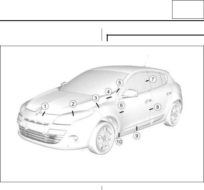
Vehicle panel gaps: Adjustment value |
B32
137528
|
No. |
Location |
Clearances (mm) |
||||
|
|
|
|
|
|
|
|
|
(1) |
bonnet / front bumper |
3.5 |
± 1.5 |
|||
|
|
|
|
|
|
|
|
|
(2) |
bonnet / headlight |
2 ± 1.7 |
||||
|
|
|
|
|
|
|
|
|
(3) |
bonnet / front wing |
3.5 |
± 1.1 |
|||
|
|
|
|
|
|
|
|
|
(4) |
bonnet / front wing |
3.5 |
± 1.1 |
|||
|
|
|
|
|
|
|
|
|
(5) |
front wing / A-pillar |
4 |
|
|||
|
|
|
|
|
|
|
|
|
(6) |
front wing / front side door |
4 ± 0.8 |
||||
|
|
|
|
|
|
|
|
|
(7) |
front side door / rear side door |
4.5 |
± 1.5 |
|||
|
|
|
|
|
|
|
|
|
(8) |
front side door / rear side door |
4.2 |
± 1.2 |
|||
|
|
|
|
|
|
|
|
|
(9) |
front side door / sill panel |
4.5 |
± 1.5 |
|||
|
|
|
|
|
|
|
|
|
(10) |
front wing / sill panel |
2.5 |
± 1 |
|||
|
|
|
|
|
|
|
|
|
|
|
|
|
|
|
|
|
|
|
|
|
|
|
|
|
|
|
|
|
|
|
|
|
|
|
|
|
|
|
|
01C-1
VEHICLE BODYWORK SPECIFICATIONS |
01C |
Vehicle panel gaps: Adjustment value |
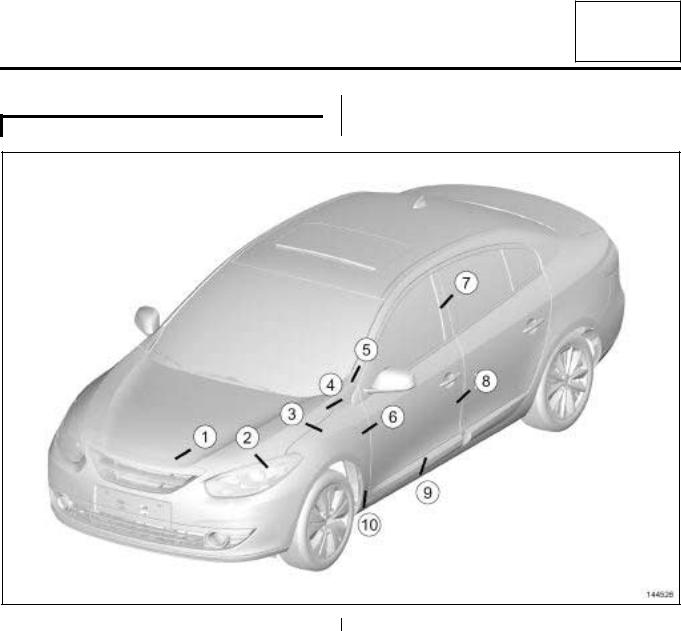
L38
144526
|
No. |
Location |
Clearances (mm) |
||||
|
|
|
|
|
|
|
|
|
(1) |
bonnet / front bumper |
3.5 |
± 1.5 |
|||
|
|
|
|
|
|
|
|
|
(2) |
bonnet / headlight |
3 ± 1.9 |
||||
|
|
|
|
|
|
|
|
|
(3) |
bonnet / front wing |
3.5 |
± 1.5 |
|||
|
|
|
|
|
|
|
|
|
(4) |
bonnet / front wing |
3.5 |
± 1.5 |
|||
|
|
|
|
|
|
|
|
|
(5) |
front wing / A-pillar |
4 |
|
|||
|
|
|
|
|
|
|
|
|
(6) |
front wing / front side door |
4 ± 1 |
||||
|
|
|
|
|
|
|
|
|
(7) |
front side door / rear side door |
4.5 |
± 1.7 |
|||
|
|
|
|
|
|
|
|
|
(8) |
front side door / rear side door |
4.5 |
± 1.2 |
|||
|
|
|
|
|
|
|
|
|
(9) |
front side door / sill panel |
4.5 |
± 1.5 |
|||
|
|
|
|
|
|
|
|
|
(10) |
front wing / sill panel |
2.5 |
± 1 |
|||
|
|
|
|
|
|
|
|
|
|
|
|
|
|
|
|
|
|
|
|
|
|
|
|
|
|
|
|
|
|
|
|
|
|
|
|
|
|
|
|
01C-2
VEHICLE BODYWORK SPECIFICATIONS |
01C |
Vehicle panel gaps: Adjustment value |
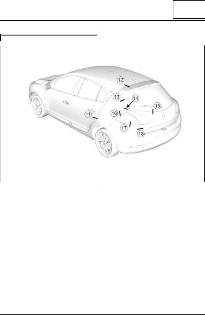
B32
137529
|
No. |
Location |
Clearances (mm) |
|||||
|
|
|
|
|
|
|
|
|
|
(11) |
rear side door / rear wing |
4 |
± |
0.8 |
|||
|
|
|
|
|
|
|
|
|
|
(12) |
roof / tailgate |
5 |
± |
1.5 |
|||
|
|
|
|
|
|
|
|
|
|
(13) |
tailgate / rear wing |
4.5 |
± 2 |
||||
|
|
|
|
|
|
|
|
|
|
(14) |
tailgate / rear wing |
4 |
± |
1.7 |
|||
|
|
|
|
|
|
|
|
|
|
(15) |
tailgate / rear screen |
3 |
± |
1 |
|||
|
|
|
|
|
|
|
|
|
|
(16) |
rear wing / rear light |
1 |
± |
0.7 |
|||
|
|
|
|
|
|
|
|
|
|
(17) |
rear bumper / rear light |
1.5 |
± 1 |
||||
|
|
|
|
|
|
|
|
|
|
(18) |
tailgate / rear bumper |
4 |
± |
2 |
|||
|
|
|
|
|
|
|
|
|
|
|
|
|
|
|
|
|
|
|
|
|
|
|
|
|
|
|
|
|
|
|
|
|
|
|
|
01C-3
VEHICLE BODYWORK SPECIFICATIONS |
01C |
Vehicle panel gaps: Adjustment value |
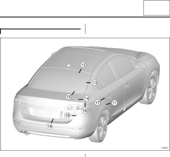
L38
144527
|
No. |
Location |
Clearances (mm) |
|||||
|
|
|
|
|
|
|
|
|
|
(11) |
rear side door / rear wing panel |
4 |
± |
0.8 |
|||
|
|
|
|
|
|
|
|
|
|
(12) |
roof / rear screen |
4 |
± |
1.4 |
|||
|
|
|
|
|
|
|
|
|
|
(13) |
rear screen / rear wing panel |
3 |
± |
2 |
|||
|
|
|
|
|
|
|
|
|
|
(14) |
boot lid / rear wing panel |
1.5 |
± 1.5 |
||||
|
|
|
|
|
|
|
|
|
|
(15) |
boot lid / rear screen |
4 |
± |
1.9 |
|||
|
|
|
|
|
|
|
|
|
|
(16) |
rear wing panel / rear light |
1.5 |
± 1.5 |
||||
|
|
|
|
|
|
|
|
|
|
(17) |
rear wing panel / fuel filler flap cover |
|
2.5± 1 |
||||
|
|
|
|
|
|
|
|
|
|
(18) |
boot lid / rear bumper |
4.5 |
± 1.9 |
||||
|
|
|
|
|
|
|
|
|
|
(19) |
boot lid / rear bumper |
6 |
± |
2.2 |
|||
|
|
|
|
|
|
|
|
|
|
|
|
|
|
|
|
|
|
|
|
|
|
|
|
|
|
|
|
|
|
|
|
|
|
|
|
|
|
|
|
|
|
|
|
|
01C-4
MECHANICAL INTRODUCTION |
01D |
Tightening torques: General information |
I - TABLE OF STANDARD TORQUES
|
Fastenings |
Standard |
|
||
|
|
|
|
tightening |
|
|
Diameter |
|
Property |
|
|
|
|
torque |
|
||
|
|
|
class |
(N.m) |
|
|
|
|
|
|
|
|
M6 |
8.8 |
10 |
|
|
|
|
|
|
|
|
|
M8 |
8.8 |
25 |
|
|
|
|
|
|
|
|
|
M10 |
8.8 |
50 |
|
|
|
|
|
|
|
|
|
M10 |
10.9 |
62 |
|
|
|
|
|
|
|
|
|
M12 |
10.9 |
105 |
|
|
|
|
|
|
|
|
|
M14 |
10.9 |
180 |
|
|
|
|
|
|
|
|
|
M16 |
10.9 |
280 |
|
|
|
|
|
|
|
|
|
M18 |
10.9 |
400 |
|
|
|
|
|
|
|
|
Special notes on electrical earths |
|
||||
|
|
|
|
|
|
|
Fastenings |
|
Standard |
|
|
|
|
|
tightening |
|
|
|
Diameter |
|
|
|
|
|
|
torque |
|
|
|
|
|
|
(N.m) |
|
|
|
|
|
|
|
|
|
M6 |
8 |
|
|
|
|
|
|
|
|
|
|
M8 |
21 |
|
|
|
|
|
|
|
|
|
|
M10 |
44 |
|
|
|
|
|
|
|
|
|
|
|
|
|
|
|
|
|
|
|
|
|
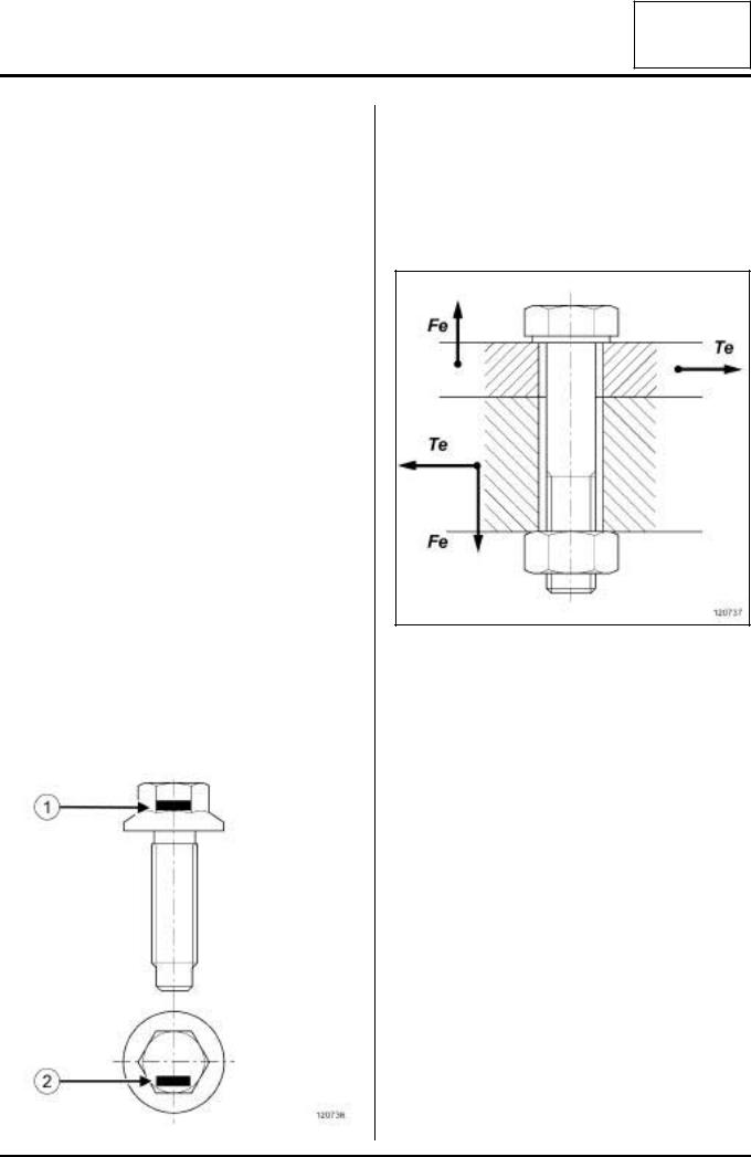
The property class is indicated on the bolt (1) or (2) .
II - FUNCTION OF A BOLTED ASSEMBLY
The bolting system connects parts of an assembly to prevent their separation or sliding when submitted to exterior forces.
Exterior forces
120737
The assembly is submitted to forces that are:
-static and / or dynamic,
-simple (e.g. simple traction),
-multiple (traction + flexion + torsion).
120736
01D-1
MECHANICAL INTRODUCTION |
01D |
Tightening torques: General information |
Creating tension (or preload) F0
120738
The assembly is held together by the tension created in the bolt when it is tightened.
A reliable assembly is only possible if the correct tension is used:
-insufficient tension: risk of loosening,
-too much tension: risk of deformation of the parts to be assembled, or shearing of the bolt.
|
120739 |
(3) |
Bolt |
(4) |
Assembled components |
(5) |
Extension of the bolt |
(6) |
Non-tightened assembly |
(7) |
Tightened assembly |
(X1) |
compression of the assembly |
(Fo) |
tension |
(C) |
tightening torque |
Customer complaints resulting from incorrect tightening may be, following assembly, a safety issue (fire, loss of control of the vehicle etc.), an immobilising fault or a noise.
III - TIGHTENING PROCEDURES
The two controlled tightening procedures adapted to automotive repairs because of their low cost and simple operation are torque tightening and angle tightening (also called torque and angle).
1 - Torque tightening
This is the most commonly used procedure. Is consists of tightening until a given resisting torque is reached, known as tightening torque.
The tightening torque is distributed in a large part as friction torque (under the head and in the thread) and in a small part as useful torque (to create the tension).
This practise spreads the tension significantly due to the variation in the friction coefficients from one assembly to another and the uncertainty of the tightening procedures and methods.
2 - Angle tightening
The principle consists of putting the parts of the assembly in contact using a mating torque (approximately 25 to 30% of the final torque) then to tighten to a determined angle.
This method, which is not dependent on the friction of the tightened assembly, gives more precise results than torque tightening.
IV - OBSERVING THE TIGHTENING TORQUES AND ANGLES
Bolted assemblies whose tightening torques and angles are explicitly specified in the removal / refitting procedures must be observed using the appropriate tools (torque wrench, angle measuring disc). Failure to observe this can lead to safety risks, immobilising faults or unwanted noises.
For other bolted assemblies, non-measured tightening (using standard spanners) is acceptable. Nevertheless, the corresponding tightening torque is indicated in the table of standard tightening torques.
V - RECOMMENDED TIGHTENING TOOLS
For measured tightening, the repairer must have available torque wrenches to tighten from 4 to 400 N.m as well as an angle measuring disc.
The torque wrenches used may be click type or electronic.
01D-2

MECHANICAL INTRODUCTION |
01D |
Tightening torques: General information |
For example:
-1 torque wrench 4 - 40 N.m,
-1 torque wrench 20 - 100 N.m,
-1 torque wrench 80 - 400 N.m,
-1 angle measurement disc.
The torque wrenches used must comply with the ISO 6789 standard. They must be calibrated regularly following the supplier's recommendations using the appropriate procedures.
VI - PRECAUTIONS WHEN USING A CLICK TYPE TORQUE WRENCH
A click type torque wrench is a manual tightening tool. The trigger mechanism causes a break or disengagement of the wrench past a force threshold.
This threshold depends on the setting of the wrench but also depends on the way the wrench is handled.
When used following best practises, the accuracy of the tightness when using a click type torque wrench is
± 15%.
The instructions to be observed are:
120740
(6) |
lever arm |
- Place the hand in the centre of the handle. An incorrectly positioned hand on the handle will alter the trigger threshold.
120741
-Pull the wrench gently and steadily, without applying any torsion. Excessive tightening speed as well as jerkiness are major causes of overtightening. Any torsion applied to the wrench will alter the trigger threshold.
-Hold the wrench on the bolt using a minimum of effort. Any effort applied to the wrench head will alter the trigger threshold.
120742
-Apply the tightening effort perpendicular to the mounting observing a tolerance of ± 15˚ relative to the perpendicularity. If the wrench is not perpendicular to the mounting axis, this will result in insufficient tightening.
-Stop tightening as soon as the wrench is triggered. Continued tightening after the wrench is triggered will lead to overtightening.
01D-3
MECHANICAL INTRODUCTION |
01D |
Tightening torques: General information |
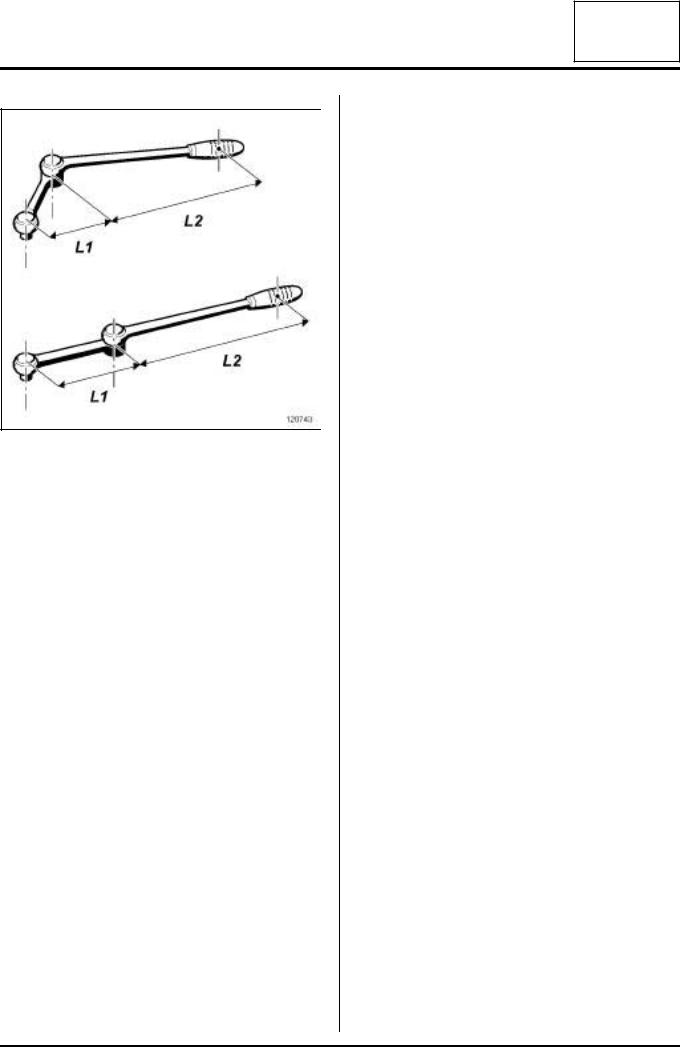
120743
If the length of the wrench is modified (extending the handle, adapting an end piece) it is essential to recalibrate the wrench to its new configuration.
Modifying the length of the wrench will modify its trigger threshold.
Use the formula: C1 = CO x L2 / (L1+L2)
-CO: torque to apply,
-C1: adjustment torque to be displayed on the wrench,
-L1: length of the extension,
-L2: length of the wrench.
Unless there are special instructions in the repair method, a universal joint (CARDAN joint type) should be used for measured tightening. Using a universal joint will result in a difference between the set torque of the wrench and the actual torque applied.
Before storing the wrench, loosen the adjustment spring completely. A wrench stored with a spring under tension will lose its tightening accuracy.
VII - PRECAUTIONS WHEN USING ELECTRONIC TORQUE WRENCHES
An electronic torque wrench is a manual tightening tool. The tightening torque and, depending on the model, the angle is read directly.
When used following best practises, the accuracy of the tightness when using an electronic torque wrench is ± 5%.
Electronic torque wrenches are not affected by the position of the operator's hand.
It is advisable to handle the wrench with care and to stop tightening when the required value is displayed on the wrench.
01D-4
LIFTING EQUIPMENT |
02A |
Vehicle: Towing and lifting |
Equipment required
safety strap(s)
I - TOWING
WARNING
See the current towing regulations in each country.
Never use the drive shafts as attachment points.
The towing points may only be used for towing on the road.
Never use the towing points for removing the vehicle from a ditch or to lift the vehicle, either directly or indirectly.
Screw in and lock the towing ring before towing.
Vehicles fitted with automatic transmission:
-It is preferable to transport the vehicle on a flatbed or tow it by lifting the front wheels. As an exception the vehicle may be towed with the wheels on the ground but at a speed below 12 mph (20 km/h) and over a maximum distance of 18 miles (30 km) (with the gear lever in neutral).
Vehicles fitted with Renault Card:
-If the vehicle battery is flat, the steering column remains locked. In this case, fit a new battery or connect to an electrical source to lock the airbag computer using the diagnostic tool, (see Fault finding - Replacement of components) (88C, Airbags and pretensioners), which unlocks the steering column.
-If it is not possible to lock the airbag computer, the front of the vehicle must be lifted.
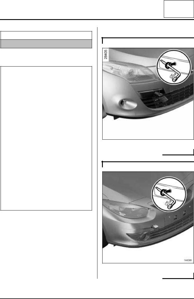
1 - position of front attachment point
B32
137700
L38
144388
02A-1

LIFTING EQUIPMENT |
02A |
Vehicle: Towing and lifting |
2 - position of rear attachment point
B32
137702
L38
144389
Fully screw in the tow eye supplied in the onboard vehicle tool kit located in the luggage compartment inside the emergency spare wheel.
II - LIFTING BY TROLLEY JACK
IMPORTANT
To prevent any accidents, the trolley jack must only be used to lift and/or move the vehicle. The vehicle height must be maintained with axle stands which are strong enough to support the weight of the vehicle.
137695
137698
To mount the vehicle on axle stands, the entire vehicle must be lifted on one side at (3) , (1) ,and axle stands must be placed under the reinforcements provided as jacking points for the vehicle's own jack at4() , (2) .
02A-2
LIFTING EQUIPMENT |
02A |
Vehicle: Towing and lifting |
III - LIFTING ON A LIFT
1 - Safety advice reminder
131005
Safety advice reminder:
If it is necessary to remove heavy components from the vehicle, it is preferable to use a four-post lift.
There is a danger that the vehicle will tilt on a two-post lift after certain components have been removed (e.g. engine and transmission assembly, rear axle, gearbox). Fit the safety strap(s) available from the Parts Department.
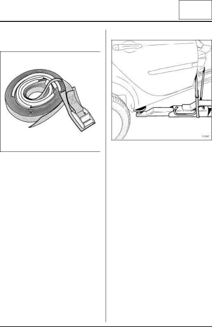
2 - Fitting the straps
112347
Fitting the straps:
For safety reasons, these straps must always be in perfect condition. Replace them as soon as they show signs of wear.
When fitting the straps, check that the seats and fragile parts of the vehicle are correctly protected.
a - Tilting towards the front
Pass the strap under the rear right-hand arm of the lift.
Pass the strap through the inside of the vehicle.
Pass the strap under the rear left-hand arm of the lift.
Pass the belt through the inside of the vehicle again.
Tighten the strap.
b - tilting towards the rear
Pass the strap under the front right-hand arm of the lift.
Pass the strap through the inside of the vehicle.
Pass the strap under the front left-hand arm of the lift.
Pass the belt through the inside of the vehicle again.
Tighten the strap.
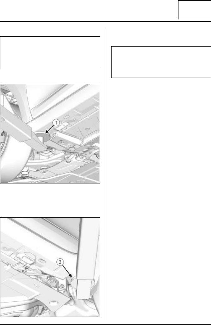
c - Permitted jacking points
To lift the vehicle, position the pads of the lifting arms as shown below, taking care not to damage the underside of the sill panel.
02A-3
LIFTING EQUIPMENT |
02A |
Vehicle: Towing and lifting |
IMPORTANT
Only the jacking points described in this section allow the vehicle to be raised in complete safety.
Do not raise the vehicle using points other than those described in this section.
Front lifting points
137692
Position the lift arms under the side cross members (1)
.
Rear lifting points
137696
Position the lift arms under the end of the sill panel body flanges (3) .
Note:
If this arrangement is not possible, notably when underbody supports are being used for bodywork rebuilding on a body jig bench, depending on the case, proceed as follows.
02A-4

LIFTING EQUIPMENT |
02A |
Vehicle: Towing and lifting |
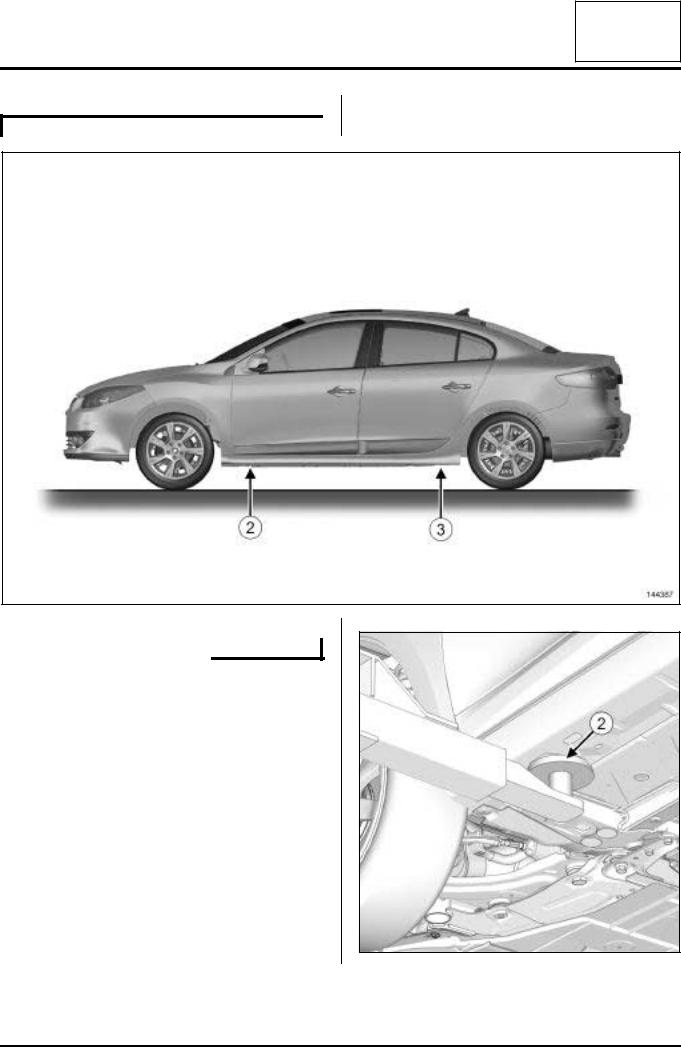
IV - DISENGAGING THE JACKING POINTS
1 - Disengaging the front side cross members
B32
137705
02A-5
LIFTING EQUIPMENT |
02A |
Vehicle: Towing and lifting |
L38
144387
Detailed view of front support points (2)
Support the vehicle at the jacking points at the front (2) and under the sill panel body flanges at the rear (3) .
137694
02A-6
LIFTING EQUIPMENT |
02A |
Vehicle: Towing and lifting |
IMPORTANT
This situation increases the risk of the vehicle tilting forwards; removing components from the rear section of the vehicle is therefore prohibited.
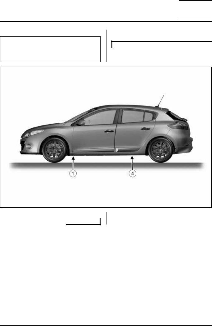
2 - disengaging the rear sill panel body flanges
B32
137705
02A-7
LIFTING EQUIPMENT |
02A |
Vehicle: Towing and lifting |
L38
144387
Detailed view of rear support points (4)
Support the vehicle under the side cross members at the front (1) , and under the jacking points at the rear
(4) .
137697
02A-8

LIFTING EQUIPMENT |
02A |
Vehicle: Towing and lifting |
IMPORTANT
In this instance, the risk of the vehicle tilting towards the rear is high. It is forbidden to remove components from the front section of the vehicle.
02A-9
COLLISION |
03B |
Vehicle involved in an impact: Impact fault finding |
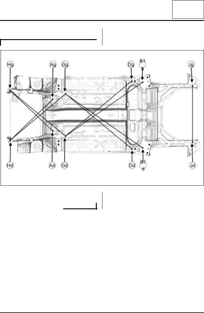
I - CHECKING THE SUBFRAME
B32
137224
a
03B-1

COLLISION |
03B |
Vehicle involved in an impact: Impact fault finding |
L38
142677
a |
- |
(Dg) - (Jd) = 1667 mm |
||
|
- |
(Dd) - (Jg) = 1695 mm |
||
a |
|
|
|
(Jg) - (Jd) = 1087 mm |
|
|
- |
||
|
|
|
|
|
|
|
|
|
|
|
Note: |
|
|
|
|
the front and rear end points are not symmetri- |
|
|
|
|
cal. To check them, measure the centre-to-centre |
|
|
|
|
distance of these points. |
|
|
|
|
|
|
|
|
Chronological order of checks
Front impact:
-(Dg) - (Gd) = (Dd) - (Gg)
-(Gg) - (Hd) = 1400 mm
-(Gd) - (Hg) = 1390 mm
-(Hg) - (Hd) = 968 mm Rear impact:
-(Dg) - (Gd) = (Dd) - (Gd)
-(Gg) - (B1d) = (Gd) - (B1g)
03B-2

COLLISION |
03B |
Vehicle involved in an impact: Impact fault finding |
II - DETAILED VIEW OF INSPECTION POINTS
Points Hg and Hd (side member front leader pin)
137227
Points Gg and Gd (front side member rear leader pin)
136911
Points Dg and Dd
136909
points B1g and B1d (rear axle mounting)
136909
a
03B-3
COLLISION |
03B |
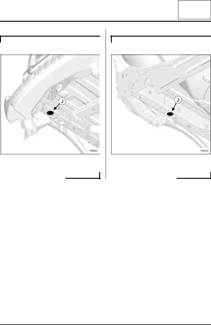
Vehicle involved in an impact: Impact fault finding |
B32
Points Jg and Jd (side member rear leader pin)
144420
a
L38
Points Jg and Jd (side member rear leader pin)
144422
a
03B-4

|
CONSUMABLES - PRODUCTS |
|
04B |
||
|
Vehicle: Parts and consumables for the repair |
||||
|
|
|
|
|
|
Consumables for mechanical repair: |
|
|
|
||
|
|
|
|
|
|
|
DEFINITION |
|
PACKAGING |
PART NUMBER |
|
|
|
|
|
|
|
|
|
|
MECHANICAL SEALANTS |
|
|
|
|
|
|
|
|
|
SILICOR |
|
85 g tube |
77 11 236 470 |
|
|
sealing paste |
|
|
|
|
|
|
|
|
|
|
|
MASTIXO |
|
100 g tube |
77 11 236 172 |
|
|
Joint face seal |
|
|
|
|
|
|
|
|
|
|
|
BEARING SEALING KIT |
|
Kit |
77 11 237 896 |
|
|
For crankshaft bearing cap side |
|
|
|
|
|
sealing |
|
|
|
|
|
|
|
|
|
|
|
SILICONE ADHESIVE SEAL |
|
100 g cartridge |
77 11 227 484 |
|
|
Engine and gearbox sealing paste |
|
|
|
|
|
|
|
|
|
|
|
TRANSPARENT SEALING MAS- |
|
45 g tube |
77 11 223 369 |
|
|
TIC |
|
|
|
|
|
|
|
|
|
|
|
SILICOJOINT |
|
90 g tube |
77 11 236 469 |
|
|
|
|
|
|
|
|
LOCTITE ADHESIVE 597 |
|
Cartridge |
77 11 219 705 |
|
|
Sealing paste for PXX gearboxes |
|
|
|
|
|
|
|
|
|
|
|
RESIN ADHESIVE or SEALING |
|
25 ml tube |
77 11 237 640 |
|
|
RESIN |
|
|
|
|
|
Sealing resin for engine and gear- |
|
|
|
|
|
box covers |
|
|
|
|
|
|
|
|
|
|
|
EXHAUST MASTIC |
|
1.5 kg tin |
77 01 421 161 |
|
|
For exhaust pipe union seals |
|
|
|
|
|
|
|
|
|
|
|
LEAK DETECTOR |
|
400 ml aerosol |
77 11 236 176 |
|
|
|
|
|
|
|
|
|
|
ADHESIVES |
|
|
|
|
|
|
|
|
|
FRENETANCHE |
|
50 ml bottle |
77 11 236 471 |
|
|
Sealing the threading at low and |
|
|
|
|
|
medium pressure |
|
|
|
|
|
|
|
|
|
|
|
HIGH-STRENGTH THREADLOCK |
|
50 ml bottle |
77 11 230 112 |
|
|
For locking bolts |
|
|
|
|
|
|
|
|
|
|
|
SEALING RESIN |
|
50 ml bottle |
77 11 236 472 |
|
|
For locking the bearings |
|
|
|
|
|
|
|
|
|
|
|
|
|
LUBRICANT CLEANERS |
|
|
|
|
|
|
|
|
|
NÉTELEC |
|
150 ml aerosol |
77 11 225 871 |
|
|
Avoid bad contacts in electrical cir- |
|
|
|
|
|
cuits |
|
|
|
|
|
|
|
|
|
|
04B-1
|
CONSUMABLES - PRODUCTS |
|
04B |
||
|
Vehicle: Parts and consumables for the repair |
||||
|
|
|
|
|
|
|
|
|
|
|
|
|
INJECTOR CLEANER |
355 ml container |
77 11 224 188 or 77 11 225 539 |
||
|
|
|
|
|
|
|
CLOTH FOR INJECTION SYSTEM |
|
77 11 211 707 |
|
|
|
|
|
|
|
|
|
SUPER RELEASING AGENT |
500 ml aerosol |
77 11 236 166 |
|
|
|
|
|
|
|
|
|
SUPER RELEASING AGENT |
250 ml aerosol |
77 11 420 439 |
|
|
|
|
|
|
|
|
|
SUPER CLEANER FOR JOINT |
300 ml aerosol |
77 11 238 181 |
|
|
|
FACES |
|
|
|
|
|
For cleaning joint faces |
|
|
|
|
|
|
|
|
|
|
|
SURFACE CLEANER |
5 L container |
77 01 404 178 |
|
|
|
|
|
|
|
|
|
SILICONE LUBRICANT |
500 ml aerosol |
77 11 236 168 |
|
|
|
|
|
|
|
|
|
SILICONE-FREE LUBRICANT |
500 ml aerosol |
77 11 236 167 |
|
|
|
|
|
|
|
|
|
BRAKE CLEANER |
|
600 ml aerosol |
77 11 422 413 |
|
|
|
|
|
|
|
|
|
150 ml aerosol |
77 11 422 414 |
|
|
|
|
|
|
||
|
|
|
|
|
|
|
BIO BRAKE CLEANER |
750 ml spray bottle |
77 11 427 217 |
|
|
|
|
|
|
|
|
|
AIR CONDITIONING CLEANER |
250 ml aerosol |
77 11 230 498 |
|
|
|
|
|
|
|
|
|
CARBURETTOR CLEANER |
Aerosol |
77 11 236 177 |
|
|
|
|
|
|
|
|
|
IXTAR ENGINE CLEANER |
400 ml can |
77 11 229 365 |
|
|
|
|
|
|
|
|
|
|
|
GREASE |
|
|
|
|
|
|
|
|
|
BR2+ GREASE |
1 kg pack |
77 01 421 145 |
|
|
|
For: |
|
|
|
|
|
- the lower arm bearings, |
|
|
|
|
|
- the anti-roll bar grooves, |
|
|
|
|
|
- the driveshaft splines. |
|
|
|
|
|
|
|
|
|
|
|
SILICONE GREASE |
100 g tube |
77 11 419 216 |
|
|
|
For: |
|
|
|
|
|
- the tubular rear axle bushes, |
|
|
|
|
|
- the anti-roll bar bushes. |
|
|
|
|
|
|
|
|
|
|
|
COPPER ANTI-SEIZE GREASE |
85 g tube |
77 11 236 173 |
|
|
|
Grease for turbochargers (high |
|
|
|
|
|
temperature) |
|
|
|
|
|
|
|
|
|
|
|
COPPER-ALUMINIUM LUBRI- |
500 ml aerosol |
77 11 236 169 |
|
|
|
CANT |
|
|
|
|
|
Grease for turbochargers (high |
|
|
|
|
|
temperature) |
|
|
|
|
|
|
|
|
|
|
|
GREASE |
180 g sachets |
77 11 420 011 |
|
|
|
For driveshaft seals |
|
|
|
|
|
|
|
|
|
|
|
|
|
|
|
|
04B-2
|
CONSUMABLES - PRODUCTS |
04B |
||||
|
Vehicle: Parts and consumables for the repair |
|||||
|
|
|
|
|
|
|
|
|
|
|
|
|
|
|
WHITE GREASE |
400 ml aerosol |
|
77 11 236 174 |
|
|
|
For wheel sensors |
|
|
|
|
|
|
|
|
|
|
|
|
|
MULTIPURPOSE GREASE |
|
500 ml aerosol |
|
77 11 236 170 |
|
|
|
|
|
|
|
|
|
|
250 ml aerosol |
|
77 11 236 171 |
|
|
|
|
|
|
|
||
|
|
|
|
|
|
|
|
FLUORSTAR 2L |
100 g tube |
|
82 00 168 855 |
|
|
|
Silicone-free electric sealing grease |
|
|
|
|
|
|
|
|
|
|
|
|
|
|
|
LACQUER |
|
|
|
|
|
|
|
|
|
|
|
JELT ARGENT |
5 g bottle |
|
77 11 230 111 |
|
|
|
Varnish for repairing heated rear |
|
|
|
|
|
|
screens |
|
|
|
|
|
|
|
|
|
|
|
|
|
|
|
BRAKE |
|
|
|
|
|
|
|
|
|
|
|
DOT 4, ISO CLASS 6, RENAULT |
0.5 L container |
|
77 11 218 589 |
|
|
|
STANDARD: 03-50-006, |
|
|
|
|
|
|
|
5 L container |
|
77 11 238 318 |
|
|
|
For vehicles with and without elec- |
|
|
|
||
|
|
|
|
|
|
|
|
|
|
|
|
|
|
|
tronic stability program (ESP) |
25 L container |
|
77 11 238 319 |
|
|
|
|
|
|
|
|
|
|
DOT 4, ISO CLASS 4, RENAULT |
|
0.5 L container |
|
77 11 172 381 |
|
|
|
|
|
|
||
|
STANDARD: 03-50-005 |
5 L container |
|
77 01 395 503 |
|
|
|
|
|
|
|
||
|
Authorised for vehicles without ESP |
|
|
|
|
|
|
|
25 L container |
|
77 11 171 926 |
|
|
|
|
|
|
|
||
|
|
|
|
|
|
|
|
DOT 4 |
0.5 L container |
|
86 71 000 000 |
|
|
|
|
|
|
|
|
|
|
Authorised for vehicles without |
5 L container |
|
86 71 014 277 |
|
|
|
ESP, without clutch with hydraulic |
|
|
|
|
|
|
|
|
|
|
|
|
|
tappet |
25 L container |
|
86 71 014 278 |
|
|
|
|
|
|
|
|
|
|
|
|
COOLING SYSTEM |
|
|
|
|
|
|
|
|
|
|
|
ANTIFREEZE (TYPE D) |
1 L container |
|
77 11 170 548 |
|
|
|
|
|
|
|
|
|
|
|
|
1 L container |
|
77 11 171 589 |
|
|
|
|
|
|
|
|
|
COOLANT (TYPE D) |
2 L container |
|
77 11 170 545 |
|
|
|
|
|
|
|
|
|
|
|
|
5 L container |
|
77 11 170 546 |
|
|
|
|
|
|
|
|
|
|
|
OIL |
|
|
|
|
|
|
|
|
||
|
ENGINE OIL |
(see Engine oil: Specifications) (Technical Note 6013A, 04A, Lubri- |
||||
|
|
|
|
cants) |
|
|
|
|
|
|
|||
|
|
|
(see Manual gearbox oil: Specifications) (Technical Note 6012A, 04A, |
|||
|
|
|
|
Lubricants) |
|
|
|
|
|
|
|||
|
GEARBOX OIL |
(see Automatic gearbox oil: Specifications) (Technical Note 6012A, |
||||
|
|
04A, Lubricants) |
|
|||
|
|
|
|
|
||
|
|
|
|
|||
|
|
|
(see Sequential gearbox oil: Specifications) (Technical Note 6012A, |
|||
|
|
|
|
04A, Lubricants) |
|
|
|
|
|
|
|
|
|
|
|
|
|
|
|
|
04B-3
|
CONSUMABLES - PRODUCTS |
04B |
||||
|
Vehicle: Parts and consumables for the repair |
|||||
|
|
|
|
|
|
|
|
|
|
|
|
||
|
AXLE OIL |
(see Rear axle oil: Specifications) (Technical Note 6012A, 04A, Lubri- |
||||
|
|
|
|
cants) |
|
|
|
|
|
|
|
|
|
|
ELF RENAULT MATIC D2 |
2 L container |
|
77 01 402 037 |
|
|
|
Oil for power-assisted steering: |
|
|
|
|
|
|
Pump connected, pump assembly |
|
|
|
|
|
|
(except Laguna III) |
|
|
|
|
|
|
|
|
|
|
|
|
|
TOTA L P O W E R - A S S I S T E D |
1 L container |
|
|
|
|
|
STEERING FLUID |
|
|
|
|
|
|
Oil for power-assisted steering: |
|
|
|
|
|
|
Pump assembly (Laguna III) |
|
|
|
|
|
|
|
|
|
|
|
|
|
PLANETELF PAG 488 |
|
|
77 11 172 668 |
|
|
|
|
|
250 ml container |
|
|
|
|
SANDEN SP 10 |
|
77 01 419 313 |
|
||
|
Oil for air conditioning compressor |
|
|
|
|
|
|
|
|
|
|
|
|
|
|
|
TYRES |
|
|
|
|
|
|
|
|
|
|
|
TYRE PASTE |
|
1 kg pack |
|
77 11 223 052 |
|
|
|
|
|
|
|
|
|
|
5 kg pack |
|
77 11 223 053 |
|
|
|
|
|
|
|
||
|
|
|
|
|
|
|
|
TYRE REPAIR AGENT |
|
400 ml tube |
|
77 11 221 296 |
|
|
|
|
|
|
|
|
|
|
300 ml tube |
|
77 11 222 802 |
|
|
|
|
|
|
|
||
|
|
|
|
|
|
|
|
|
|
BLANKING PLUG |
|
|
|
|
|
|
|
|
|
|
|
Engine type |
Injection type |
|
Part no. |
|
|
|
|
|
|
|
|
|
|
F5R |
|
|
77 01 206 382 |
|
|
|
|
|
|
|
|
|
|
F8Q |
|
|
77 01 206 340 |
|
|
|
|
|
|
|
|
|
|
F9Q |
|
|
77 01 208 229 |
|
|
|
|
|
|
|
|
|
|
G9T AND G9U |
|
|
77 01 208 229 |
|
|
|
|
|
|
|
|
|
|
K9K |
DELPHI |
|
77 01 206 804 |
|
|
|
|
|
|
|
|
|
|
K9K |
SIEMENS |
|
77 01 476 857 |
|
|
|
|
|
|
|
|
|
|
M9R |
|
|
77 01 209 062 |
|
|
|
|
|
|
|
|
|
|
P9X |
|
|
77 01 474 730 |
|
|
|
|
|
|
|
|
|
|
ZD3 |
|
|
77 01 208 229 |
|
|
|
|
|
|
|
|
|
|
|
|
MISCELLANEOUS |
|
|
|
|
|
|
|
|
|
|
|
GREY ABRASIVE PAD |
|
|
77 01 405 943 |
|
|
|
|
|
|
|
|
|
Consumables for bodywork repair: |
|
|
|
|
||
|
|
|
|
|
|
|
|
|
|
HOLLOW SECTION WAX |
|
|
|
|
|
|
|
|
||
|
SPR CC |
1 L container |
|
77 11 172 672 |
|
|
|
|
|
|
|
|
|
|
|
|
|
|
|
|
04B-4
Loading...