


 Loading...
RENAULT 44C1, 44C2, 44T, 44V, 45D2 Wiring Diagrams
...
|
|
|
|
|
|
|
|
|
|
|
RENAULT V.I. |
||
|
|
|
|
|||
70 139 - GB - 11/2003 |
||||||
|
|
|||||
ELECTRICS |
|
|
|
|
||
|
|
|
|
|
|
|
|
RANGE |
FAMILY |
|
VARIANT |
|
|
|
|
|
|
|
|
|
|
|
44C1 |
|
|
|
|
|
|
|
|
|
|
|
|
MIDLUM 12-16 t Euro 3 |
44C2 |
|
|
|
|
|
|
|
|
|
||
|
44T |
|
|
|
||
|
|
|
|
|
||
|
|
|
|
|
|
|
|
|
44V |
|
|
|
|
|
|
|
|
|
|
|
|
|
45D2 |
|
|
|
|
|
|
|
|
|
|
|
|
MIDLUM 16-18 t |
45D3 |
|
|
|
|
|
|
|
|
|
|
|
|
|
45E2 |
|
- |
|
|
|
|
|
|
|
|
|
|
|
47XA |
|
|
|
|
|
|
|
|
|
|
|
|
MIDLUM 4x4 |
47XC |
|
|
|
|
|
|
|
|
|
|
|
|
|
47XF |
|
|
|
|
|
|
|
|
|
|
|
|
|
42B3 |
|
|
|
|
|
|
|
|
|
|
|
|
MIDLUM 7-12 t |
42B4 |
|
|
|
|
|
|
|
|
|
|
|
|
|
45D2 |
|
|
|
|
|
|
|
|
|
|
|
The above information may change in the course of time. Only the "Consult" section of the workshop manuals repertory in standard N° 10320 serves as reference.
70 139 |
70.1 |
|
70.1 . . . .
70.1 . . . .
50 21 014 630
https://www.truck-manuals.net/

70 139 |
1 |
|
CONTENTS
Generalities. . . . . . . . . . . . . . . . . . . . . . . . . . . . . . . . . . . . . . . . . . . . . . . . . . |
.A-1 → 8 |
|
|
Electrical diagram. . . . . . . . . . . . . . . . . . . . . . . . . . . . . . . . . . . . . . . . . . . . . |
B-1 → 83 |
|
|
Dealer Network and Customer Follow-up . . . . . . . . . . . . . . . . . . . . . . . . . |
.C-1 → 2 |
|
|
|
© RENAULT V.I. 11/2003 - Imprimé en France - le 11/2003 |
|
50 21 014 630 |
|
||
https://www.truck-manuals.net/ |
|
|
|
||

70 139 |
A-1 |
|
GENERALITIES
RENAULT V.I. 11/2003
https://www.truck-manuals.net/
|
70 139 |
|
|
|
|
A-2 |
|
|
|
|
|
|
|
|
|
|
|
Warnings
In this document, safety instructions are symbolized as follows:
DANGER! NON-OBSERVANCE OF THE PROCEDURE DESCRIBED OR LACK OF CARE OR ATTENTION, RISK CAUSING SERIOUS INJURY OR EVEN DEATH.
WARNING! Any different or inappropriate working method risks causing damage to the product.
NOTE! Draws attention to particular or important points of the method.
Comply without fail with the regulations in force relative to the recovery and treatment of used parts and waste.
RENAULT V.I. 11/2003
https://www.truck-manuals.net/

70 139 |
A-3 |
|
Vehicle voluminal breakdown
The vehicle is broken down into several zones each designated by an item number. Heightwise breakdown
Reserved for the bodywork, 4 zones designated by a small letter Widthwise breakdown
3 zones designated by a capital letter
A:RH side and RH sidemember
B:Central part
C:LH side and LH sidemember Lengthwise breakdown:
9 zones designated by a figure. Zone 7 is specific for 6x4 - 6x6. Zone 1 indicates:
- on the chassis, the bumper and the components it supports.
-on the cab, the front end components accessible through the grille Example:
A1: bumper RH section (headlamps, ...) C3: LH front wheel (ABS sensor, ...) C2b: dashboard
A3c: passenger's seat
RENAULT V.I. 11/2003
https://www.truck-manuals.net/
|
70 139 |
|
|
|
|
A-4 |
|
|
|
|
|
|
|
|
|
|
|
How to read the diagrams
Definition of an illustration
The diagram consists of several plates.
The plates are defined in the bottom right-hand corner by:
–a six-figure number, which is the reference number of the illustration.
–a letter, which is the revision index of the illustration. This letter is to be found on the same line as the reference number.
–a three-figure number, which defines the folio number.
A diagram plate is broken down into 5 zones in the vertical direction.
These zones are identified by letters ranging from A to E.
Definitions of symbols used in a diagram
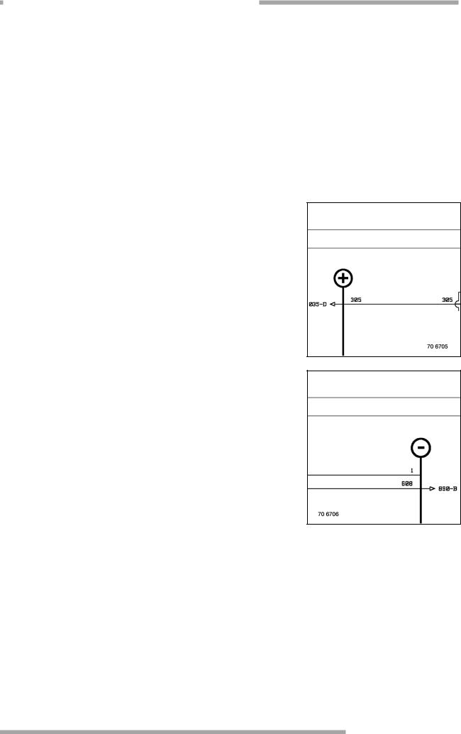
Cross-references
The folio co-ordinates to be found on the right always refer back to a preceding page.
The folio co-ordinates to be found on the left always refer forward to a following page.
The cross-reference is defined by:
–a three-figure number, which gives information on the order number of the destination folio,
–a letter, which gives information on the zone in which the cross-reference is to be found.
RENAULT V.I. 11/2003
https://www.truck-manuals.net/
70 139 |
A-5 |
|
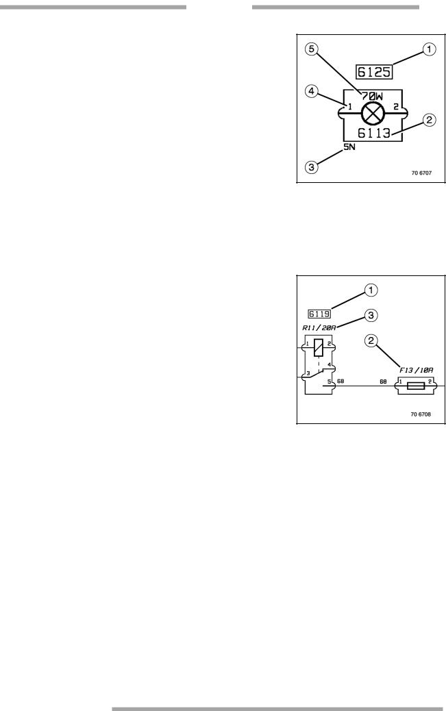
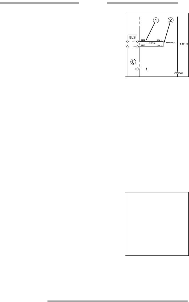
Appliances
Each appliance shown in the diagram is identified by an after-sales code number.
If the after-sales code number is framed (item (1) of the illustration opposite), it indicates a single appliance or an assembly comprising several functions.
If the after-sales code number is not framed (item (2) of the illustration opposite), it indicates a single appliance. It is then to be found inside the symbol.
Underneath each appliance, we define, wherever possible, the colour and the number of ways of the connector with which it is associated (item (3) of the illustration opposite).
All the terminals of each appliance are defined by a numerical or alphanumerical code number, if necessary (item (4) of the illustration opposite).
For certain appliances, we define, wherever possible, the power with which it is associated (item (5) of the illustration opposite).
Fuses and relays
Relays are designated by an after-sales code number (item (1) of the illustration opposite).
They are also designated by an alphanumerical code number and by the value of the rated current capable of crossing them
(item (2 - 3) of the illustration opposite).
Fuses are merely designated by an alphanumerical code number and by the value of the rated current capable of crossing them.
Polarities
Polarities are identified by a numerical code number.
For each function, there is one same, single code number. Example:
2 = battery "positive" direct current power supply.
1 = earth.
Circuits where polarities are represented by dotted lines indicate a connection solution or an optional assembly.
RENAULT V.I. 11/2003
https://www.truck-manuals.net/
|
|
|
|
70 139 |
|
|
|
|
|
|
|
|
|
|
A-6 |
|
|
|
|
|
|
|
|
|
|
||
|
|
|
|
|
|
|
Graphic conventions |
|
|
|
|||
|
|
|
||||
|
|
|
|
|
|
|
|
|
|
|
|
|
|
A folio cross-reference can consist of two sections.
The first in a zone of the diagram (item (1A) of the illustration above).
The second to the right or left of the zone of the diagram according to its destination (item (1B) of the illustration above).
In all cases, both sections are always on the same line.
This principle is applied whenever it makes it possible to avoid polarity crossovers that may prejudice clear legibility of the diagram.
A folio cross-reference may be made by fuse (5) or by warning light (4).
If an intersection is not reinforced by a connection point, the polarities cross over and are distinct (3).
If an intersection is reinforced by a connection point, we have the same level of information on the wires (same potential)
It is possible for extra connection points to be applied to the diagram for legibility reasons (item (2) of the illustration above).
It is possible for a function to have several technical responses. In this case, we call upon the notion of "variant" or "option".
This notion is represented by a figure inside a circle. This symbol is placed on the polarity in question.
An explanation to be found on the page opposite the diagram describes the possible options.
If a folio represents several assemblies, it goes without saying that a vehicle can have only one single option.
RENAULT V.I. 11/2003
https://www.truck-manuals.net/
70 139 |
A-7 |
|
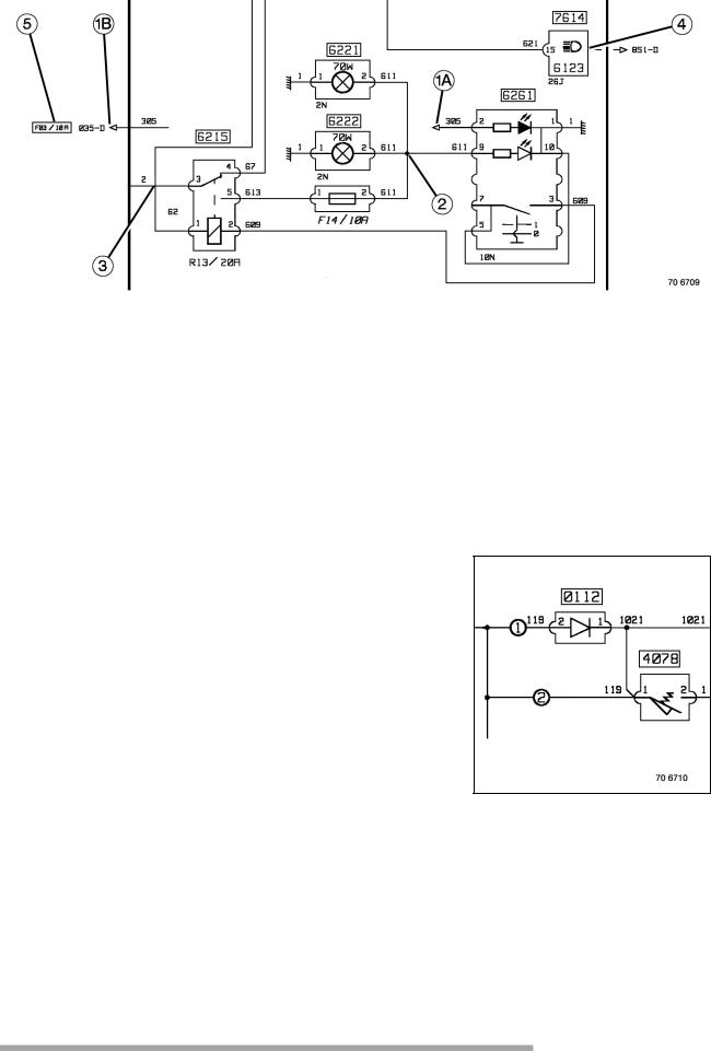
To make for easier reading, communication buses are represented as follows:
Only the ends of conductors are represented (item (1) of the illustration opposite).
The "body" of the wiring harness is shown in diagrammatic form by one thicker single line. Page cross-references are made according to the same principle as for polarities (item (2) of the illustration opposite).
Wiring harnesses
Each plate represents the routing of one or several wiring harnesses connected to a sub-assembly or function. The outline of the vehicle pinpoints the wiring harnesses.
Connectors identified by the letter "C" followed by figures are indicated on each harness. A key opposite each plate defines their assignment.
The detail of the connectors connected to wiring harnesses on the plate enable the polarity of each pocket to be situated.
Key to connectors:
C129 ................................4618 - Driver's overhead lamp C129: connector item number
4618: appliance reference number
Driver's overhead light: key to the apparatus
The appliance reference number and key provide the link to the electrical diagram. Optional wiring harnesses:
Connectors assigned with indexes "*1" or "*2" belong to optional harnesses. Example of connector reference number:
C129: connector on standard harness C137 *1: connector on option 1 harness C141 *2: connector on option 2 harness
At the end of the key is shown the make-up of each optional harness.
Detail of connectors:
Each drawing represents the structure of a connector.
Example:
A:Outline of the connector
B:Item number and location of the wires
C:Reference number of the appliance
D:Item number of the connector
E:Option and/or colour of the connector
RENAULT V.I. 11/2003
https://www.truck-manuals.net/
|
70 139 |
|
|
|
|
A-8 |
|
|
|
|
|
|
|
|
|
|
|
Electrical distribution
The cab electrical distributing box contains the majority of the fuses and relays necessary for operation of the vehicle.
Fuses and relays that are connected on the electrical distribution box are represented as surrounded by a fine dotted line in the electrical diagram.
Each face of the electrical distribution box is detailed in the "Electrical distribution unit" chapter.
The chassis-cab connection box enables the information to be found inside the cab to cross the bulkhead and be routed to the outside and vice versa.
Each connector of the chassis-cab connection box is detailed in the "Electrical distribution unit" chapter.
Precautions to be taken when making electrical measurement readings
Protection of appliances
Bearing in mind the presence of numerous electronic appliances, the use of a test lamp is to be avoided. Preferably use a needle or digital type multi-meter.
It is forbidden to apply voltage to the terminals of electronic appliances or you may cause irreparable damage to the hardware. Consequently, no line continuity measurement should be made on the wires without having previously disconnected the appliances from the lines concerned.
RENAULT V.I. 11/2003
https://www.truck-manuals.net/
70 139 |
B-1 |
|
ELECTRICAL DIAGRAM
RENAULT V.I. 11/2003
https://www.truck-manuals.net/
|
|
|
|
70 139 |
|
|
|
|
|
|
|
|
|
|
B-2 |
|
|
|
|
|
|
|
|
|
|
||
|
|
|
|
|
|
|
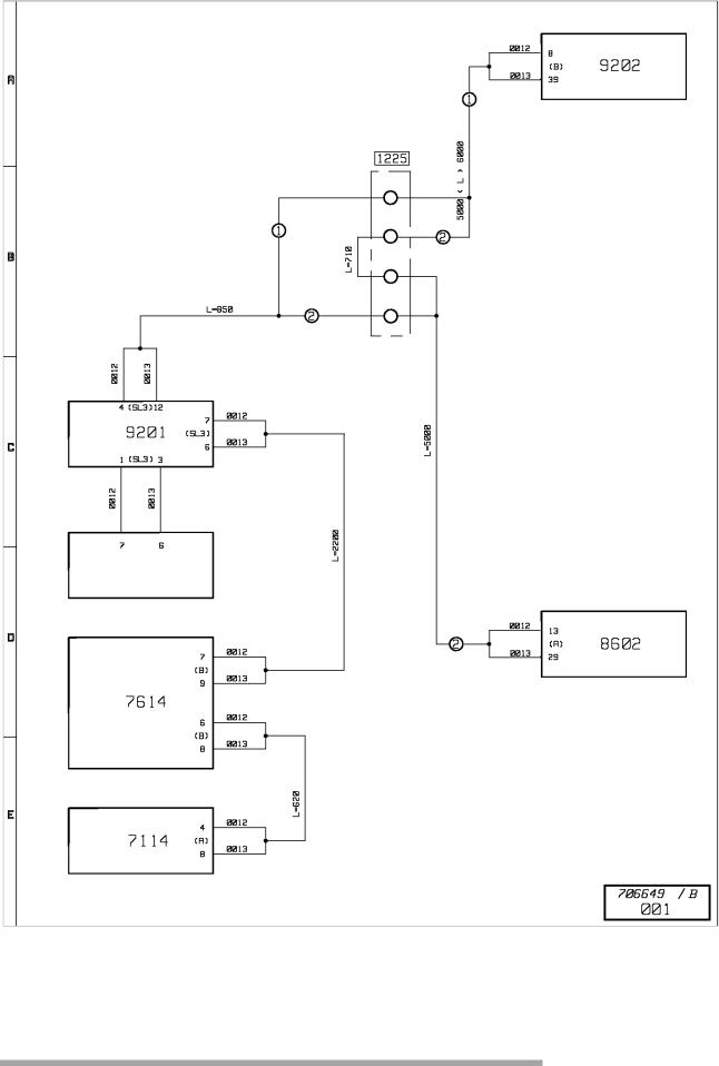
CAN BUS "J1939" architecture |
|
|
|
|||
|
|
|
||||
|
|
|
|
|
|
|
|
|
|
|
|
|
|
RENAULT V.I. 11/2003
https://www.truck-manuals.net/

|
|
70 139 |
|
|
|
|
|
|
|
|
|
|
|
|
|
|
|
|
|
|
|
|
|
B-3 |
||
|
|
|
|
|
|
|||
|
|
|
|
|
|
|
|
|
|
|
|
|
|
|
|
|
|
CAN BUS "J1939" architecture |
|
|
|
|
|
|||
Key to appliances |
|
|
|
|
|
|||
|
|
|
|
|
|
|
|
|
|
Code |
Name of function |
|
Location |
|
|
||
|
N° |
|
|
|||||
|
|
|
|
|
|
|
|
|
|
|
|
|
|
|
|||
1225 |
Chassis cab junction box |
|
A2c |
|||||
7114 |
Electronic tachograph |
|
C2b |
|||||
7614 |
Principal display |
|
C2b |
|||||
8602 |
Automatic gearbox ECU |
|
B3c |
|||||
9201 |
Vehicle master ECU (VECU) |
|
B3c |
|||||
9202 |
Engine master ECU (EECU) |
|
B3c |
|||||
1: with "ALLISON" gearbox
2: without "ALLISON" gearbox
RENAULT V.I. 11/2003
https://www.truck-manuals.net/
|
|
|
|
70 139 |
|
|
|
|
|
|
|
|
|
|
B-4 |
|
|
|
|
|
|
|
|
|
|
||
|
|
|
|
|
|
|
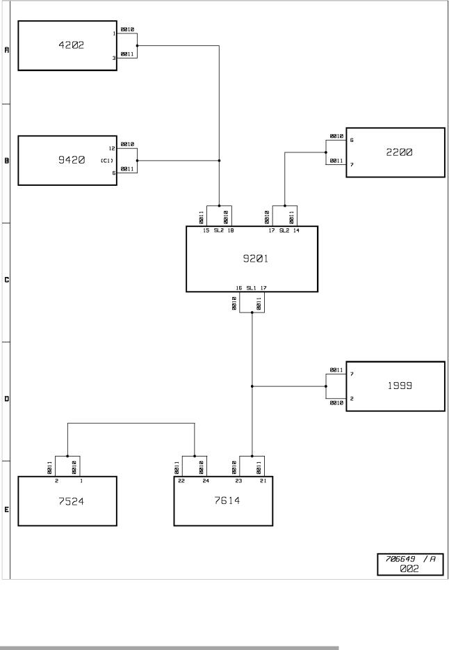
CAN BUS "J1587" architecture |
|
|
|
|||
|
|
|
||||
|
|
|
|
|
|
|
|
|
|
|
|
|
|
RENAULT V.I. 11/2003
https://www.truck-manuals.net/

|
|
70 139 |
|
|
|
|
|
|
|
|
|
|
|
|
|
|
|
|
|
|
|
|
|
B-5 |
||
|
|
|
|
|
|
|||
|
|
|
|
|
|
|
|
|
|
|
|
|
|
|
|
|
|
CAN BUS "J1587" architecture |
|
|
|
|
|
|||
Key to appliances |
|
|
|
|
|
|||
|
|
|
|
|
|
|
|
|
|
Code |
Name of function |
|
Location |
|
|
||
|
N° |
|
|
|||||
|
|
|
|
|
|
|
|
|
|
|
|
|
|
|
|||
1999 |
ECU for bodybuilder pre-arrangement |
|
A2c |
|||||
2200 |
Anti-theft electronic box |
|
C2a |
|||||
4202 |
Radio |
|
C2a |
|||||
7524 |
"SAE" diagnostic socket |
|
C3c |
|||||
7614 |
Principal display |
|
A2b |
|||||
9201 |
Vehicle master ECU (VECU) |
|
B3c |
|||||
9420 |
Anti-theft alarm ECU |
|
C2a |
|||||
RENAULT V.I. 11/2003
https://www.truck-manuals.net/
|
|
|
|
70 139 |
|
|
|
|
|
|
|
|
|
|
B-6 |
|
|
|
|
|
|
|
|
|
|
||
|
|
|
|
|
|
|
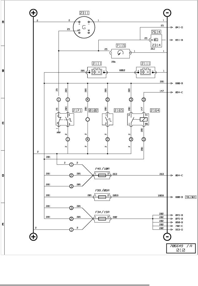
Energy production |
|
|
|
|||
|
|
|
||||
|
|
|
|
|
|
|
|
|
|
|
|
|
|
RENAULT V.I. 11/2003
https://www.truck-manuals.net/

|
|
70 139 |
|
|
|
|
|
|
|
|
|
|
|
|
|
|
|
|
|
|
|
|
|
B-7 |
||
|
|
|
|
|
|
|||
|
|
|
|
|
|
|
|
|
|
|
|
|
|
|
|
|
|
Energy production |
|
|
|
|
|
|||
Key to appliances |
|
|
|
|
|
|||
|
|
|
|
|
|
|
|
|
|
Code |
Name of function |
|
Location |
|
|
||
|
N° |
|
|
|||||
|
|
|
|
|
|
|
|
|
|
|
|
|
|
|
|||
0102 |
Electrical connection terminal |
|
C4d |
|||||
2111 |
Battery (set of batteries) |
|
C4d |
|||||
2164 |
Electrical master switch |
|
C4d |
|||||
2165 |
Master switch |
|
C4d |
|||||
2171 |
Pneumatic master switch |
|
C4d |
|||||
2311 |
Alternator |
|
B2c |
|||||
2314 |
Battery charge warning lamp |
|
C2b |
|||||
7115 |
Hourmeter |
|
A3c |
|||||
7614 |
Principal display |
|
C2b |
|||||
1: with "ADR" master switch
2: with mechanical master switch
3: with electrical master switch
4: without master switch
RENAULT V.I. 11/2003
https://www.truck-manuals.net/
|
|
|
|
70 139 |
|
|
|
|
|
|
|
|
|
|
B-8 |
|
|
|
|
|
|
|
|
|
|
||
|
|
|
|
|
|
|
After ignition distribution |
|
|
|
|||
|
|
|
||||
|
|
|
|
|
|
|
|
|
|
|
|
|
|
RENAULT V.I. 11/2003
https://www.truck-manuals.net/

70 139 |
B-9 |
|
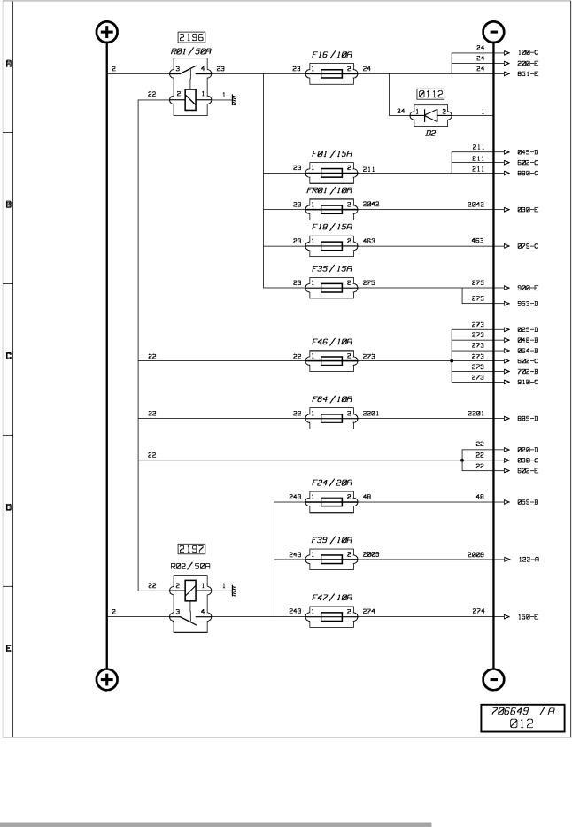
After ignition distribution
Key to appliances
Code |
Name of function |
Location |
|
N° |
|||
|
|
||
|
|
|
|
0112 |
Diode(s) |
A2c |
|
2196 |
After ignition power supply relay N°1 |
A2c |
|
2197 |
After ignition power supply relay N°2 |
A2c |
RENAULT V.I. 11/2003
https://www.truck-manuals.net/
|
|
|
|
70 139 |
|
|
|
|
|
|
|
|
|
|
B-10 |
|
|
|
|
|
|
|
|
|
|
||
|
|
|
|
|
|
|
Engine starting |
|
|
|
|||
|
|
|
||||
|
|
|
|
|
|
|
|
|
|
|
|
|
|
RENAULT V.I. 11/2003
https://www.truck-manuals.net/
70 139 |
B-11 |
|
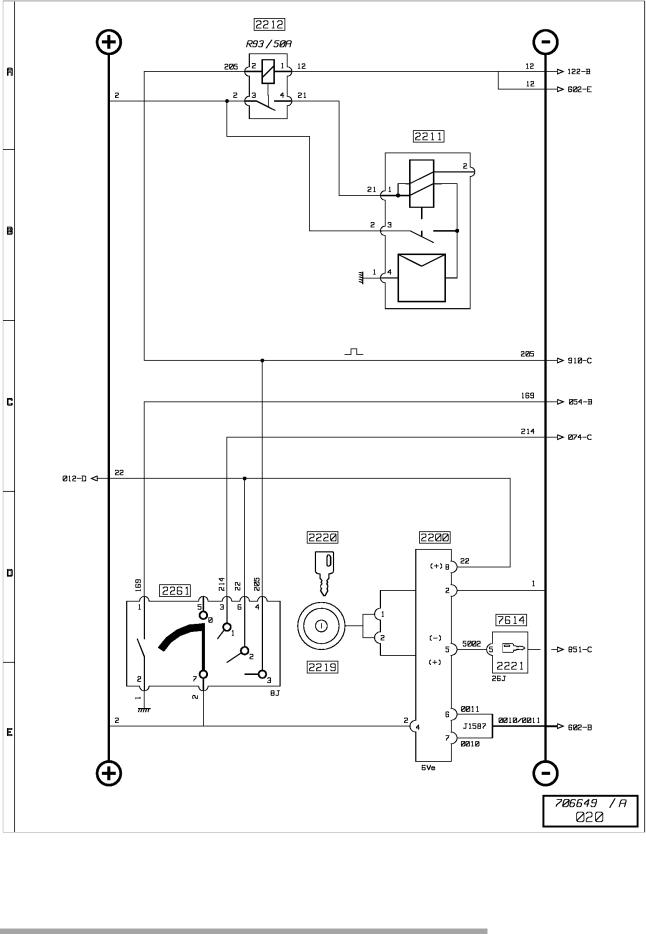
Engine starting
Key to appliances
Code |
Name of function |
Location |
|
N° |
|||
|
|
||
|
|
|
|
2200 |
Anti-theft electronic box |
C2a |
|
2211 |
Starter |
B3c |
|
2212 |
Starting relay |
A2c |
|
2219 |
Transponder antenna |
C2a |
|
2220 |
Transponder ignition key |
C2a |
|
2221 |
Electronic anti-theft "Information" warning lamp |
C2b |
|
2261 |
Steering lock and starting control |
C2b |
|
7614 |
Principal display |
C2b |
RENAULT V.I. 11/2003
https://www.truck-manuals.net/
|
|
|
|
70 139 |
|
|
|
|
|
|
|
|
|
|
B-12 |
|
|
|
|
|
|
|
|
|
|
||
|
|
|
|
|
|
|
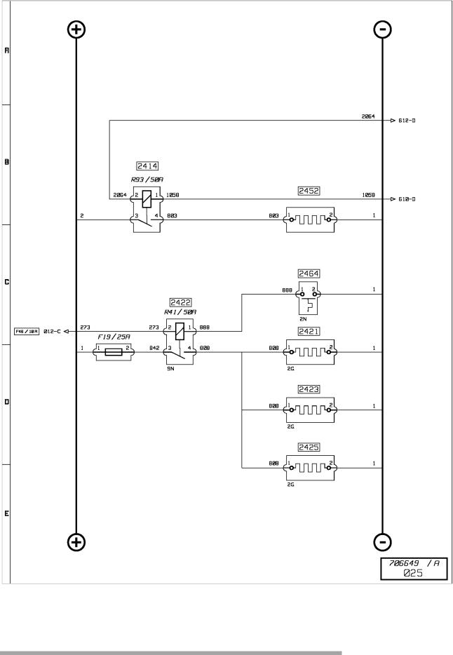
Engine starting aid |
|
|
|
|||
|
|
|
||||
|
|
|
|
|
|
|
|
|
|
|
|
|
|
RENAULT V.I. 11/2003
https://www.truck-manuals.net/

|
|
70 139 |
|
|
|
|
|
|
|
|
|
|
|
|
|
|
|
|
|
|
|
|
|
B-13 |
||
|
|
|
|
|
|
|||
|
|
|
|
|
|
|
|
|
|
|
|
|
|
|
|
|
|
Engine starting aid |
|
|
|
|
|
|||
Key to appliances |
|
|
|
|
|
|||
|
|
|
|
|
|
|
|
|
|
Code |
Name of function |
|
Location |
|
|
||
|
N° |
|
|
|||||
|
|
|
|
|
|
|
|
|
|
|
|
|
|
|
|||
2414 |
Preheating relay N°1 |
|
B3d |
|||||
|
|
|
|
|
B2c |
|||
2421 |
Fuel preheater resistor N°1 |
|
B3c |
|||||
2422 |
Fuel preheater relay |
|
A2b |
|||||
2423 |
Fuel preheater resistor N°2 |
|
B3c |
|||||
2425 |
Fuel preheater resistor N°3 |
|
B3c |
|||||
2452 |
Preheating resistor N°1 |
|
B3c |
|||||
2464 |
Fuel preheater thermal switch |
|
B3d |
|||||
RENAULT V.I. 11/2003
https://www.truck-manuals.net/
|
70 139 |
|
|
|
|
B-14 |
|
|
|
|
|
|
|
|
|
|
|
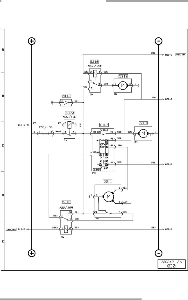
Windscreen wiper(s) and headlamps wash
RENAULT V.I. 11/2003
https://www.truck-manuals.net/

|
|
70 139 |
|
|
|
|
|
|
|
|
|
|
|
|
|
|
|
|
|
|
|
|
|
B-15 |
||
|
|
|
|
|
|
|||
|
|
|
|
|
|
|
|
|
|
|
|
|
|
|
|
|
|
Windscreen wiper(s) and headlamps wash |
|
|
|
|
||||
Key to appliances |
|
|
|
|
||||
|
|
|
|
|
|
|
|
|
|
Code |
Name of function |
Location |
|
|
|||
|
N° |
|
||||||
|
|
|
|
|
|
|
|
|
|
|
|
|
|
||||
0112 |
Diode(s) |
A2c |
||||||
5310 |
Headlamps wash pump time-delay power supply relay |
A2c |
||||||
5311 |
Windscreen wiper motor |
B1c |
||||||
5314 |
Windscreen wash pump |
C1c |
||||||
5319 |
Headlamps wash pump motor |
A2d |
||||||
5320 |
Windscreen wiper prohibition relay |
A2c |
||||||
5364 |
Windscreen wash control |
C2b |
||||||
5368 |
Windscreen wipe control |
C2b |
||||||
6167 |
Steering column fingertip controls |
C2b |
||||||
RENAULT V.I. 11/2003
https://www.truck-manuals.net/
|
|
|
|
70 139 |
|
|
|
|
|
|
|
|
|
|
B-16 |
|
|
|
|
|
|
|
|
|
|
||
|
|
|
|
|
|
|
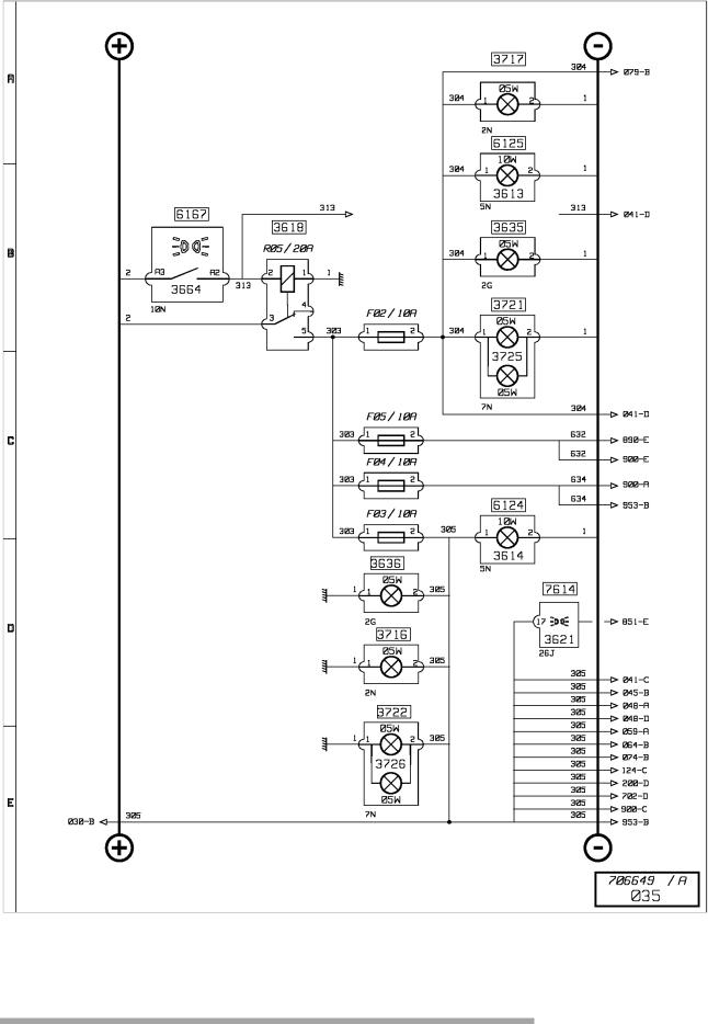
Side/parking lights |
|
|
|
|||
|
|
|
||||
|
|
|
|
|
|
|
|
|
|
|
|
|
|
RENAULT V.I. 11/2003
https://www.truck-manuals.net/

|
|
70 139 |
|
|
|
|
|
|
|
|
|
|
|
|
|
|
|
|
|
|
|
|
|
B-17 |
||
|
|
|
|
|
|
|||
|
|
|
|
|
|
|
|
|
|
|
|
|
|
|
|
|
|
Side/parking lights |
|
|
|
|
||||
Key to appliances |
|
|
|
|
||||
|
|
|
|
|
|
|
|
|
|
Code |
Name of function |
Location |
|
|
|||
|
N° |
|
||||||
|
|
|
|
|
|
|
|
|
|
|
|
|
|
||||
3613 |
RH front side/parking lamp |
A1d |
||||||
3614 |
LH front side/parking lamp |
C1d |
||||||
3618 |
Side/parking lights power supply relay N°1 |
A2b |
||||||
3621 |
Side/parking lights warning lamp |
C2b |
||||||
3635 |
RH marker lights (bodybuilder equipment) |
A2c |
||||||
3636 |
LH marker lights (bodybuilder equipment) |
A2c |
||||||
3664 |
Side/parking lights control |
C2b |
||||||
3716 |
LH central marker lamp |
C5d |
||||||
3717 |
RH central marker lamp |
A4d |
||||||
3721 |
RH rear light(s) (flashing, stop, fog, reversing, side/parking) |
A9d |
||||||
3722 |
LH rear lights (flashing, stop, fog, reverse, side/parking) |
C9d |
||||||
3725 |
RH rear side/parking lamp |
A9d |
||||||
3726 |
LH rear side/parking lamp |
C9d |
||||||
6124 |
Headlight, dipped headlight and left side lamp |
C1d |
||||||
6125 |
Headlight, dipped headlight and right side lamp |
A1d |
||||||
6167 |
Steering column fingertip controls |
C2b |
||||||
7614 |
Principal display |
C2b |
||||||
RENAULT V.I. 11/2003
https://www.truck-manuals.net/

|
70 139 |
|
|
|
|
B-18 |
|
|
|
|
|
|
|
|
|
|
|
Fog and fog driving lights / Dipped beam headlights
RENAULT V.I. 11/2003
https://www.truck-manuals.net/

|
|
70 139 |
|
|
|
|
|
|
|
|
|
|
|
|
|
|
|
|
|
|
|
|
|
B-19 |
||
|
|
|
|
|
|
|||
|
|
|
|
|
|
|
|
|
|
|
|
|
|
|
|
|
|
Fog and fog driving lights / Dipped beam headlights |
|
|
|
|
||||
Key to appliances |
|
|
|
|
||||
|
|
|
|
|
|
|
|
|
|
Code |
Name of function |
Location |
|
|
|||
|
N° |
|
||||||
|
|
|
|
|
|
|
|
|
|
|
|
|
|
||||
3500 |
LH fog lamp |
C9d |
||||||
3513 |
Fog light(s) power supply relay |
A2b |
||||||
3517 |
Fog light(s) warning lamp |
C2b |
||||||
3722 |
LH rear lights ( flashing, stop, fog, reverse, side/parking ) |
C9d |
||||||
6102 |
Dipped beam headlights control |
C2b |
||||||
6111 |
RH dipped beam headlamp |
C1d |
||||||
6112 |
LH dipped beam headlamp |
A1d |
||||||
6119 |
Dipped beam headlights relay |
A2b |
||||||
6124 |
Headlight, dipped headlight and left side lamp |
C1d |
||||||
6125 |
Headlight, dipped headlight and right side lamp |
A1d |
||||||
6132 |
Dipped beam headlights warning lamp |
C2b |
||||||
6167 |
Steering column fingertip controls |
C2b |
||||||
6211 |
LH fog driving lamp |
C1d |
||||||
6212 |
RH fog driving lamp |
A1d |
||||||
6214 |
Fog driving lights relay |
A2b |
||||||
6218 |
Fog driving lights warning lamp |
C2b |
||||||
6262 |
Fog driving lights control |
B2b |
||||||
6263 |
Fog driving light(s) control |
B2b |
||||||
7614 |
Principal display |
C2b |
||||||
RENAULT V.I. 11/2003
https://www.truck-manuals.net/
Loading...