


SC-HC30
Table of contents
 Loading...
Operating Instructions
Instrucciones de funcionamiento
Compact Stereo System
Sistema estéreo compacto
As an ENERGY STAR Partner, Panasonic has
determined that this product meets the ENERGY
STAR guidelines for energy efficiency.
Como socio de ENERGY STAR , Panasonic ha
determinado que este producto cumple con las
irectrices de la ENERGY STAR para el rendimiento
d
energético.
Model No. / Nº de modelo
SC-HC30
Dear customer
Thank you for purchasing this product.
Before connecting, operating or adjusting this product, please read the
instructions completely. Please keep this manual for future reference.
Operations in these instructions are described using remote control, but
you can do the operations with the main unit if the controls are the same.
Your unit may not look exactly as illustrated.
If you have any questions contact
1-800-211-PANA (7262)
The warranty can be found on page 15.
Please return the product registration card (if included), or
register via the Internet at: www.panasonic.com/register
Estimado cliente
Muchas gracias por comprar este producto.
Antes de conectar, operar o ajustar este producto, por favor lea
completamente las instrucciones. Sírvase guardar este manual para su
consulta futura.
Las operaciones de estas instrucciones se describen principalmente
usando el mando a distancia, pero puede realizar las mismas
operaciones en la unidad principal.
Es posible que su unidad no sea exactamente como la que se muestra.
P
Por favor devuelva la tarjeta de registro del
producto (si se incluyó) o regístrese en Internet, en:
www.panasonic.com/register
RQTX1066-2P

RQTX1066
2
ENGLISH
RQTX1066
IMPORTANT SAFETY INSTRUCTIONS
Read these operating instructions carefully before using the unit. Follow the safety instructions on the unit and the applicable safety instructions listed
below. Keep these operating instructions handy for future reference.
1) Read these instructions.
2) Keep these instructions.
3) Heed all warnings.
4) Follow all instructions.
5) Do not use this apparatus near water.
6) Clean only with dry cloth.
7)
Do not block any ventilation openings. Install in accordance with the
manufacturer’s instructions.
8)
Do not install near any heat sources such as radiators, heat registers,
stoves, or other apparatus (including amplifiers) that produce heat.
9)
Do not defeat the safety purpose of the polarized or grounding-type
plug. A polarized plug has two blades with one wider than the other.
A grounding-type plug has two blades and a third grounding prong.
The wide blade or the third prong are provided for your safety. If the
provided plug does not fit into your outlet, consult an electrician for
replacement of the obsolete outlet.
CAUTION
RISK OF ELECTRIC SHOCK
DO NOT OPEN
CAUTION: TO REDUCE THE RISK OF ELECTRIC
SHOCK, DO NOT REMOVE SCREWS.
NO USER-SERVICEABLE PARTS INSIDE.
REFER SERVICING TO QUALIFIED
SERVICE PERSONNEL.
The lightning flash with arrowhead symbol, within
an equilateral triangle, is intended to alert the user
to the presence of uninsulated “dangerous voltage”
within the product’s enclosure that may be of
sufficient magnitude to constitute a risk of electric
shock to persons.
The exclamation point within an equilateral triangle
is intended to alert the user to the presence of
important operating and maintenance (servicing)
instructions in the literature accompanying the
appliance.
CAUTION
Danger of explosion if battery is incorrectly replaced. Replace only
with the same or equivalent type recommended by the manufacturer.
Dispose of used batteries according to the manufacturer’s
instructions.
The unit should be installed near an accessible AC power outlet, with
the power cord connected directly to it.
To completely disconnect power from the unit, unplug the power cord
from the AC power outlet.
2 3
Protect the power cord from being walked on or pinched particularly
10)
at plugs, convenience receptacles, and the point where they exit from
the apparatus.
Only use attachments/accessories specified by the manufacturer.
11)
12) Use only with the cart, stand, tripod, bracket, or
table specified by the manufacturer, or sold with the
apparatus. When a cart is used, use caution when
moving the cart/apparatus combination to avoid injury
from tip-over.
Unplug this apparatus during lightning storms or when unused for long
13)
periods of time.
14)
Refer all servicing to qualified service personnel. Servicing is
required when the apparatus has been damaged in any way, such
as power-supply cord or plug is damaged, liquid has been spilled
or objects have fallen into the apparatus, the apparatus has been
exposed to rain or moisture, does not operate normally, or has been
dropped.
WARNING:
TO REDUCE THE RISK OF FIRE, ELECTRIC SHOCK
OR PRODUCT DAMAGE,
DO NO
*
T EXPOSE THIS APPARATUS TO RAIN,
MOISTURE, DRIPPING OR SPLASHING AND
THAT NO OBJECTS FILLED WITH LIQUIDS,
SUCH AS VASES, SHALL BE PLACED ON THE
APPARATUS.
USE ONLY THE RECOMMENDED ACCESSORIES.
*
DO NO
*
T REMOVE THE COVER (OR BACK);
THERE ARE NO USER SERVICEABLE PARTS
INSIDE. REFER SERVICING TO QUALIFIED
SERVICE PERSONNEL.
CAUTION!
DO NOT INSTALL OR PLACE THIS UNIT IN A
BOOKCASE, BUILT-IN CABINET OR IN ANOTHER
CONFINED SPACE. ENSURE THE UNIT IS WELL
VENTILATED. TO PREVENT RISK OF ELECTRIC SHOCK
OR FIRE HAZARD DUE TO OVERHEATING, ENSURE
THAT CURTAINS AND ANY OTHER MATERIALS DO NOT
OBSTRUCT THE VENTILATION VENTS.
CAUTION!
THIS PRODUCT UTILIZES A LASER.
USE OF CONTROLS OR ADJUSTMENTS OR
PERFORMANCE OF PROCEDURES OTHER THAN THOSE
SPECIFIED HEREIN MAY RESULT IN HAZARDOUS
RADIATION EXPOSURE.
DO NOT OPEN COVERS AND DO NOT REPAIR
YOURSELF. REFER SERVICING TO QUALIFIED
PERSONNEL.
RQTX1066
RQTX1066
3
ENGLISH
EST. 192 4
Listening caution
Selecting fine audio equipment such as the unit you’ve just purchased
is only the start of your musical enjoyment. Now it’s time to consider
how you can maximize the fun and excitement your equipment offers.
This manufacturer and the Electronic Industries Association’s Consumer
Electronics Group want you to get the most out of your equipment by
playing it at a safe level. One that lets the sound come through loud
and clear without annoying blaring or distortion–and, most importantly,
without affecting your sensitive hearing.
We recommend that you avoid prolonged exposure to excessive noise.
can be deceiving. Over time your hearing “comfort level” adapts to
Sound
higher volumes of sound. So what sounds “normal” can actually be loud
and harmful to your hearing.
Guard against this by setting your equipment at a safe level BEFORE
your hearing adapts.
To establish a safe level:
Start your volume control at a low setting.
•
Slowly increase the sound until you can hear it comfortably and
•
clearly, and without distortion.
Once you have established a comfortable sound level:
Leave it there.
•
Taking a minute to do this now will help to prevent hearing damage or
loss in the future. After all, we want you listening for a lifetime.
The model number and serial number of this product can be found on
either the back or the bottom of the unit.
Please note them in the space provided below and keep for future
reference.
MODEL NUMBER ______________________________________
SERIAL NUMBER ______________________________________
SC-HC30
User memo:
DATE OF PURCHASE __________________________________
DEALER NAME _______________________________________
DEALER ADDRESS ____________________________________
_______________________________________________
TELEPHONE NUMBER _________________________________
Product service
1. Damage requiring service — The unit should be serviced by
qualified service personnel if:
(a) The AC power supply cord or the plug has been damaged; or
(b) Objects or liquids have gotten into the unit; or
(c) The unit has been exposed to rain; or
(d) The unit does not operate normally or exhibits a marked change in
performance; or
(e) The unit has been dropped or the cabinet damaged.
Servicing — Do not attempt to service the unit beyond that described
2.
in these operating instructions. Refer all other servicing to authorized
servicing personnel.
Replacement parts — When parts need replacing ensure the servicer
3.
uses parts specified by the manufacturer or parts that have the same
characteristics as the original parts. Unauthorized substitutes may
result in fire, electric shock, or other hazards.
Safety check — After repairs or service, ask the servicer to perform
4.
safety checks to confirm that the unit is in proper working condition.
Product information
For product information or assistance with product operation:
Refer to “Customer Services Directory (United States and Puerto Rico)”
on page 15.
Table of contents
IMPORTANT SAFETY INSTRUCTIONS 2
Listening caution 3
Product service 3
Supplied accessories 4
Connections 4
Attaching the unit to a wall (Optional) 5
Control guide 8
Disc operations 9
Radio operations 10
Timer 11
Sound adjustment 11
External unit 11
Troubleshooting guide 13
Memory reset (Initialization) 14
Maintenance 14
Specifications 14
Limited Warranty 15
FCC Note:
This equipment has been tested and found to comply with the limits for
a Class B digital device, pursuant to Part 15 of the FCC Rules.
These limits are designed to provide reasonable protection against
harmful interference in a residential installation. This equipment
generates, uses and can radiate radio frequency energy and, if not
installed and used in accordance with the instructions, may cause
harmful interference to radio communications. However, there is no
guarantee that interference will not occur in a particular installation. If
this equipment does cause harmful interference to radio or television
reception, which can be determined by turning the equipment off and
on, the user is encouraged to try to correct the interference by one or
more of the following measures:
* Reorient or relocate the receiving antenna.
* Increase the separation between the equipment and receiver.
* Connect the equipment into an outlet on a circuit different from that
to which the receiver is connected.
* Consult the dealer or an experienced radio/TV technician for help.
Any unauthorized changes or modifications to this equipment would
void the user’s authority to operate this device.
This device complies with Part 15 of the FCC Rules. Operation is
subject to the following two conditions: (1) This device may not cause
harmful interference, and (2) this device must accept any interference
received, including interference that may cause undesired operation.
Responsible Party:
Panasonic Corporation of North America
One Panasonic Way
Secaucus, NJ 07094
Support Contact:
Panasonic Consumer Electronics Company
Telephone No.: 1-800-211-PANA (7262)
-If you see this symbol-
Information on Disposal in other Countries outside the
European Union
This symbol is only valid in the European Union.
If you wish to discard this product, please contact
your local authorities or dealer and ask for the
correct method of disposal.

RQTX1066
4
ENGLISH
RQTX1066
2
1
AUX
AUX
AC IN
or
“Made for iPod” means that an electronic accessory has been
designed to connect specifically to iPod and has been certified by the
developer to meet Apple performance standards.
“Works with iPhone” means that an electronic accessory has been
designed to connect specifically to iPhone and has been certified by
the developer to meet Apple performance standards.
Apple is not responsible for the operation of this device or its
compliance with safety and regulatory standards.
iPod is a trademark of Apple Inc., registered in the U.S. and other
countries. iPhone is a trademark of Apple Inc.
MPEG Layer-3 audio decoding technology licensed from Fraunhofer
IIS and Thomson.
Connections
Supplied accessories
Please check and identify the supplied accessories.
Use numbers indicated in parentheses when asking for
replacement parts. (Product numbers are correct as of
January 2010. These may be subject to change.)
To order accessories, refer to “Accessory Purchases
(United States and Puerto Rico)” on page 15.
1 AC power supply cord
(K2CB2CB00021)
1 FM indoor antenna
(RSAX0002)
1 Remote control (N2QAYB000522)
Screw accessories (RFAX1020)
2 Fixing screws
(XYN3+J10FJ)
Wall bracket accessories (RFAX1021)
1 Wall bracket
(RGQX1004)
The included AC power supply cord is for use with this unit only. Do
•
not use it with other equipment.
Do not use an AC power supply cord of other equipment.
•
B
1 AM loop antenna
(N1DYYYY00010)
2 Batteries
1 Safety holder
(RMKX1015)
Four-legged cushions
(RKAX0028-K)
Back View
Exhaust holes
45
23
g Notes on speakers
These speakers do not have magnetic shielding. Do not place
•
them near televisions, personal computers or other devices easily
influenced by magnetism.
The speaker nets cannot be removed.
•
1
Connect the FM indoor antenna.
Tape the antenna to a wall or column, in a position with the
•
least amount of interference.
Adhesive tape
FM indoor antenna
2
Connect the AM loop antenna.
AM loop antenna
Stand the antenna
4 5
Keep the loose antenna cord away from other wires and cords.•
up on its base.
Click!
3
Connect the AC power supply cord.
Connect the AC power supply cord after all other connections
are complete.
1
To household AC outlet
4
Headphones (not included)
Reduce the volume level and connect the headphones.
Plug type: 3.5 mm (1/8") stereo
Avoid listening for prolonged periods of time to prevent hearing
•
damage.
Excessive sound pressure from earphones and headphones can
•
cause hearing loss.
Listening at full volume for long periods may damage the user’s
•
ears.
Be sure to use the supplied or recommended headphones or
earphones.
5
Portable audio equipment (during AUX mode)
Plug the audio cord into the AUX jack.
Plug type: 3.5 mm (1/8") stereo
Press [AUX] and start playback from the
portable audio source.
You can select the sound input level of the portable audio
equipment.
Press [INPUT LEVEL] repeatedly to select “HIGH” or
“NORMAL”.
Switch the equalizer off or turn the volume of the portable
•
equipment down to reduce the input signal. High level of input
signal will distort the sound.
For details, refer to the instruction manual of the other equipment.
•
Cords and equipment are not included.
•

RQTX1066
RQTX1066
5
ENGLISH
Attaching the unit to a wall (Optional)
Notes on installation
g Before installation, read the “Safety precautions” and “Wall mount instructions” for correct installation.
g For optimal performance and to prevent potential problems, do not install this unit:
at locations other than vertical walls.
•
near a sprinkler or a sensor.
•
near high-voltage lines or power sources.
•
near heating device.
•
at locations where the unit is subject to vibration or impact.
•
near sources of magnetism, heat, vapor, airborne grease, etc.
•
at locations where there may be water droplets (e.g. under an air conditioner).
•
g Do not install this unit under ceiling lights (e.g. spotlight, halogen light, etc.).
Failure to do so may bend the cabinet or lead to damage caused by high heat.
g Use a proper installation method that suits the structure and material of the wall.
g Use a soft blanket or cloth to prevent damage to the product or floor during installation.
g When tightening screws, make sure the screws are not loosely-tightened or overtightened.
g Secure a safe surrounding area and pay attention to safety during installation.
g Panasonic is not liable for incidental or consequential damages resulting from improper installation or operation.
Safety precautions
WARNING!
Only a qualified building contractor shall install or uninstall this
unit.
Improper installation may cause the unit to fall, resulting in injury.
prevent injury, the unit must be securely attached to the wall in
To
accordance with the installation instructions.
Do not install the unit where it cannot support the load.
If the mounting parts are not strong enough, this may cause the unit to
fall, resulting in injury.
Do not use installation methods other than instructed.
This may cause the unit to fall and be damaged, resulting in injury.
Do not install the unit at locations other than vertical walls.
This may cause the unit to fall and be damaged, resulting in injury.
Take the safety factor for mounting strength into account
(approx. 10 times the product weight).
Insufficient strength will cause the unit to fall, resulting in injury.
The wall on which the unit is to be attached to should be capable
of supporting 20 kg (44 lb.) per screw.
Insufficient strength of the walls will cause the unit to fall in the long
run.
Do not disassemble or modify the wall-mounting hanger.
This will cause the unit to fall and be damaged, resulting in injury.
CAUTION!
Do not install this unit at humid or dusty locations, or locations
where airborne grease or steam may come into contact with the
unit, or under an air conditioner where water may drip onto the
unit.
This may have negative impact on the unit, resulting in fire or electric
shock.
3
Secure enough space of more than 30 cm (11
main unit and more than 10 cm (3
respectively. Keep space between the wall and rear of the unit
clear of obstructions.
Blocking the exhaust holes on the main unit may result in fire.
Use the designated components for installation.
Otherwise, the main unit may fall and be damaged, resulting in injury.
Prevent the mounting screws or power cord from coming into
contact with metal parts inside the wall during installation.
Failure to do so may cause electric shock.
When removing the main unit, remove the wall mounting screws
as well.
Otherwise the wall mounting screws may hit a person and lead to
injury.
Install the unit at a height where the operation buttons can be
seen for safe operation.
Operating at improper position may cause the unit to fall and be
damaged, resulting in injury.
15
/16") on the left and right sides
/16") above the
Installation accessories
Included accessories
g
•
Screw accessories (RFAX1020)
»
2 Fixing screws (XYN3+J10FJ)
»
1 Safety holder (RMKX1015)
•
Wall bracket accessories (RFAX1021)
»
1 Wall bracket (RGQX1004)
»
Four-legged cushions (RKAX0028-K)
Keep all the intended accessories out of reach of children to
prevent swallowing.
B
g Commercially available accessories (not included)
2 Wall mounting screws
•
1 Safety holder screw
•
Use screws with nominal diameter of 4 mm (5/32"), which are suitable
to the material of the wall (e.g. wood, steel, concrete, etc.).
C
C

RQTX1066
6
ENGLISH
RQTX1066
AUX
2
1
Attaching the unit to a wall (Optional) (continued)
Wall mount instructions
• Before installation, turn the unit off and disconnect the AC power supply cord plug from the AC receptacle.
• Tighten screws firmly to prevent slack in each step.
1. Detach the stand from the unit.
Unscrew the fixing screw (2 pieces) at the bottom of the unit.
A
Keep the removed screws in a safe place.
Bottom of main unit
Soft blanket
or cloth
Stand
Slide the stand off the unit.
Fixing screw
A
2. Attach the wall bracket to the back of the unit.
Align both tabs on the wall bracket and the main unit, then slide it
in until it clicks into place.
Wall bracket (bottom view)
Tab
Rear of
main unit
Secure the wall bracket with fixing screw (2 pieces).
[Tightening torque: 1.2 Nm (57/64 lb-ft) to 1.5 Nm (1
Fixing screw
3. Drive the mounting screws into the wall.
Measure and mark the position of the mounting screw (2 pieces) and drive them into the wall.
Use figures below for screw positions and measurements.
•
Please install using both wall mounting screws.
•
Use a level ruler to ensure both screws are level.
•
Use a screw which is strong enough to support the weight of at least 20 kg (44 lb.).
•
C
B
B
7
/64 lb-ft)]
Rear View
13
300 mm (11
Space required
130 mm
(5
74.8 mm
15
(2
1
/16")
/8")
6 7
/16")
500 mm (19
700 mm (27
85.5 mm (3 3/8")77.5 mm (3 1/16")
11
/16")
9
/16")
Wall
163 mm (6 7/16")
Mounting screw
Space required
C
20 kg (44 lb.) or more must be kept for
each screw.
8 mm (5/16") to 9.5 mm (3/8")
4 mm
(5/32")
2.2 mm (3/32") to 2.8 mm (7/64")
2.5 mm (3/32") to 3.5 mm (9/64")
A length which supports the strength of
RQTX1066
RQTX1066
7
ENGLISH
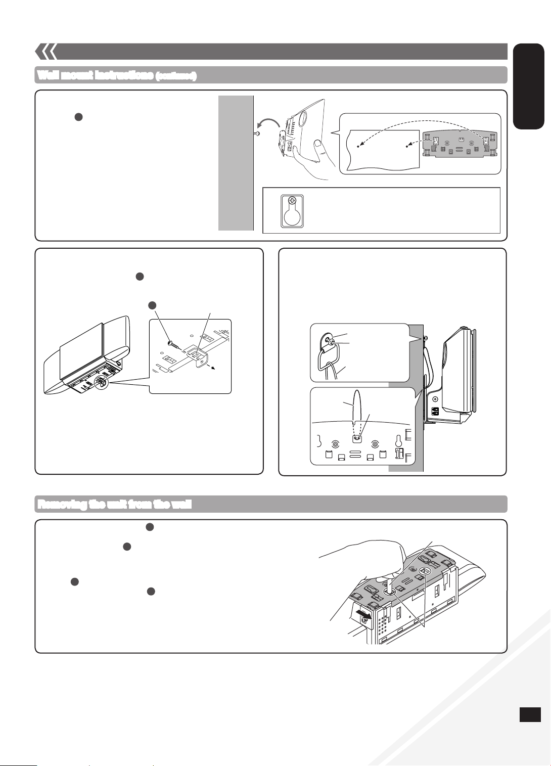
Attaching the unit to a wall (Optional) (continued)
Wall mount instructions (continued)
4. Hang the unit on the wall.
Hook the unit securely onto the mounting
•
•
C
screws .
Connect the FM/AM antenna before hanging the
main unit on the wall (➡ page 4).
After hanging the unit, release your hand carefully
to confirm the unit sits securely on the wall.
Wall
5. Install the safety holder.
Fix the safety holder onto the wall bracket.
Drive safety holder screw to secure the safety holder onto
the wall.
Safety holder screw
C
C
Safety holder
Fixed to
the wall
Wall bracket
Slot both screws into this position firmly.
g Fall-preventive measure (Optional)
Thread a wire (commercially available) through the slot on the
wall bracket before step 4 (➡ above).
Fix the wire to the wall with a screw (commercially available)
after step 5 (➡ left).
•
Fix the screw to the wire so that a slack of no more than
31
/32") is kept in the upper center part of the main unit.
5 cm (1
Metal fitting
Screw
Wire
Wire
Slot for
wire
Removing the unit from the wall
Remove safety holder screw and the safety holder.
Unmount the unit from the wall.
Unscrew fixing screw (2 pieces).
Hold down both the catches and then slide the wall bracket off the unit
(➡ right).
Reattach the stand to the bottom of the unit and secure it with fixing
Remove the mounting screw (2 pieces) from the wall.
A
screw (2 pieces).
Remove the fall-preventive wire before step if you are using it.•
C
B
C
Pen or a blunt object
Catches
RQTX1066
8
ENGLISH
RQTX1066
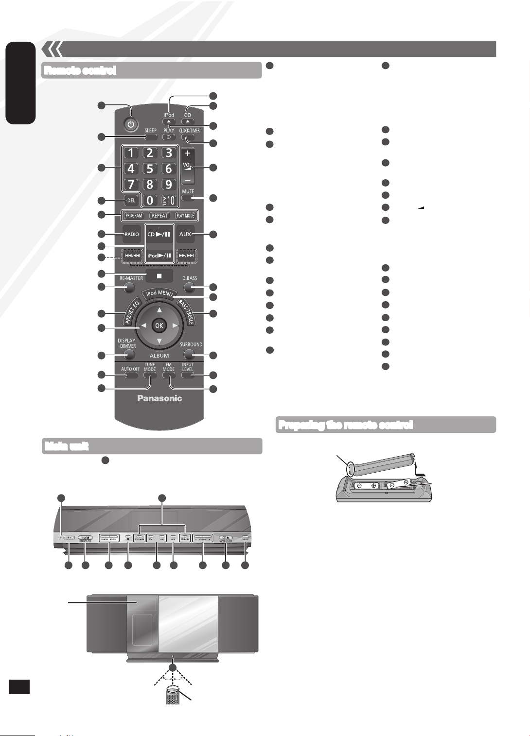
Control guide
AUDIO SYSTEM
POWER
Remote control
Refer to the numbers in parentheses for page reference.•
10]
14
[AUTO OFF]
This function allows you to turn
the unit off (except in radio mode)
after the unit is left unused for
about 30 minutes. The default
setting is ON. Press once to
cancel it.
15
[TUNE MODE] (10)
16
[;, iPod],
[iPod ;, OPEN/CLOSE] (11)
17
[;, CD],
[CD ;, OPEN/CLOSE] (9)
18
[z, PLAY] (11)
19
[CLOCK/TIMER] (11)
20
[+, VOL , –], [– VOLUME +]
21
[MUTE]
Mutes the sound. Press again to
cancel. “MUTE” is also canceled
when the volume is adjusted or
the unit is turned off.
22
[AUX] (4, 12)
23
[D.BASS] (11)
24
[iPod MENU] (11)
25
[BASS/TREBLE] (11)
26
[SURROUND] (11)
27
[INPUT LEVEL] (4)
28
[FM MODE] (10)
29
Standby indicator
30
Remote control signal sensor
Aim the remote control at the
sensor, avoiding obstacles, at a
maximum range of 7 m (23 feet)
1
Standby/on switch [^],
[8, POWER] (9, 11, 14)
Press to switch the unit from on
1
2
16
17
18
19
to standby mode or vice versa.
In standby mode, the unit is still
consuming a small amount of
power.
[SLEEP] (11)
2
3
Numeric buttons [1-9, 0,
≧
(9, 10, 12)
3
4
5
6
7
8
9
10
11
12
20
21
22
23
24
25
To select a 2-digit number
≧
e.g. 16: [
To select a 3-digit number
e.g. 226:
10] [1] [6]
≧
10] [≧ 10] [2]
[
[2] [6]
4
[DEL] (9)
5
[PROGRAM] (9, 10)
[REPEAT] (10)
[PLAY MODE] (10)
[RADIO], [FM], [AM] (10)
6
7
[CD q/h] (9, 10)
[iPod q/h] (11)
8
[u/t], [y/i] (9, 10, 11)
9
[g] (9, 11)
10
[RE-MASTER] (11)
[PRESET EQ] (11)
11
12
[e,r], [w, q] (9, 10, 11)
[OK] (9, 11, 12)
13
13
14
15
26
27
28
[DISPLAY, –DIMMER] (9)
Press and hold to dim the display
panel. Press and hold again to
cancel.
directly in front of the unit.
8
Main unit
Buttons such as function the same as the remote control. They
•
can be used interchangeably.
29
1 16 8 9 20 17 23
Display
1
Top View
Front View
Approx. 30°
7
22
6
30
Approx. 30°
Transmission window
Preparing the remote control
Place this side in before the other side.
R6/LR6, AA
■ Batteries
Use a manganese dry battery or an alkaline dry battery.
•
Insert so the poles (+ and –) match those in the remote control.
•
Remove if the remote control is not going to be used for a long period
•
of time.
Store in a cool and dark place.
•
Do not heat or expose to flame.
•
Do not leave the batteries in an automobile exposed to direct sunlight
•
for a long period of time with doors and windows closed.
Mishandling of batteries in the remote control can cause electrolyte
•
leakage, which may cause a fire.
■ Do not:
mix old and new batteries.
•
use different types of batteries at the same time.
•
take apart or short-circuit the batteries.
•
attempt to recharge alkaline or manganese batteries.
•
use the batteries if the coverings have been peeled off.
•
RQTX1066
RQTX1066
9
ENGLISH
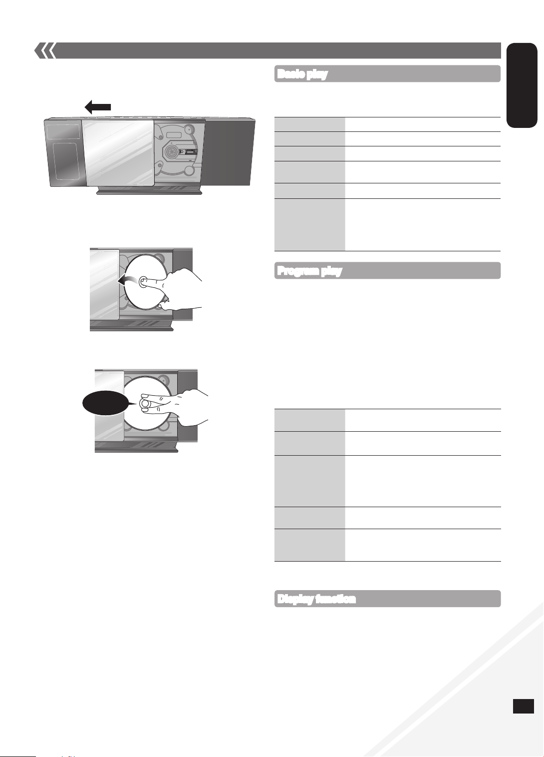
Disc operations
g Inserting a disc
Press [^] to turn the unit on.
Press [;, CD] to open the sliding door.
With the label of the disc facing towards you, tilt the disc into the
disc tray under the sliding door.
Place the disc onto the spindle in the center and then push the
disc down until it clicks into place.
Click!
Press [;, CD] to close the sliding door.
Keep fingers away from the sliding door when it is closing to avoid
possible minor injuries.
g Removing a disc
Press [;, CD] to open the sliding door.
Hold the center and the top right of the disc and pull the top right
of the disc to unlock it from the spindle.
Tilt the disc so as not to touch the sliding door and remove the
disc.
Damage may occur if the sliding door is forced closed.
•
Be careful of CD hitting the sliding door while being removed.
•
Basic play
Press [^] to turn the unit on.
Insert the disc to be played (➡ left).
Press [CD q/h] to start play.
Stop
Pause
Skip track
Search the current
track (CD)
Skip album (MP3)
Direct access play
(Play starts with the
track you select.)
Press [g].
Press [CD q/h]. Press again to resume play.
Press [u/t] or [y/i].
Press and hold [u/t] or [y/i].
Press [e,r].
CD: Press the numeric buttons to select the
track.
MP3: Press [e,r] to select the album.
Press [y/i] once and then the
numeric buttons to select the track.
Program play
Enables you to program up to 24 tracks.
Press [CD q/h] and then [g].
Press [PROGRAM].
CD: Press the numeric buttons to select the track.
To program more tracks, continue by pressing the numeric
buttons.
Press [OK] or [CD q/h] to start play.
MP3: Press [e,r] to select the album.
Press [y/i] once and then the numeric buttons to select
the track.
Press [OK].
To program more tracks, repeat step to .
Press [CD q/h] to start play.
Cancel program
mode
Replay the program Press [PROGRAM] in the stop mode and then
Check program
contents
Delete last
programmed track
Clear all
programmed tracks
The program memory is cleared when you open the sliding door.•
Press [PROGRAM] in the stop mode to clear
“PGM” indicator from the display.
[CD q/h].
Press [u/t] or [y/i] when “PGM” is
displayed in the stop mode. To check while
programming, press [PROGRAM] twice after
“PGM” appears and then press [u/t] or
[y/i].
Press [DEL] in the stop mode.
Press [g] in the stop mode.
“CLR ALL” is displayed. Within 5 seconds,
press the button again to clear all tracks.
Display function
Press [DISPLAY, –DIMMER] repeatedly during play or pause to view
the current track’s information.
Maximum number of displayable characters: approximately 30
•
This unit supports ver. 1.0 and 1.1 ID3 tags. Text data that is not
•
supported will not be displayed.
9
Loading...