


PEDL66573-02
1Semiconductor
This version: Aug. 1999 Previous version: Jun.1999
MSM66573 Family |
Preliminary |
16-Bit Microcontroller |
|
|
|
GENERAL DESCRIPTION
The MSM66573 family of highly functional CMOS 16-bit single chip microcontrollers utilize the nX-8/500S, Oki's proprietary CPU core.
A wide variety of internal multi-functioned timers provide timer functions such as compare out, capture, event counter, auto reload, and PWM, and can be used for periodic and timed measurements. In addition to the main clock and clock gear functions, there is a sub clock (32.768 kHz) that is suitable for low power applications. A three channel serial interface and a high-speed bus interface that has separate address and data buses and does not require external address latches are provided as interfaces to external devices.
With a 16-bit CPU core that enables high-speed 16-bit arithmetic computations and a variety of bit processing functions, this general-purpose microcontroller is optimally suited for Digital Audio devices such as a Mini-Disc and an MP3 player.
The flash ROM version (MSM66Q573L) programmable with a single 2.4 V (minimum) power supply and flash ROM version (MSM66Q573) programmable with a single 5 V power supply are also included in the family. These versions are easily adaptable to sudden specification changes and to new product versions.
APPLICATIONS
Digital Audio Control Systems
PC peripheral Control Systems
Office Electronics Control Systems
ORDERING INFORMATION
Order Code or Product Name |
Package |
Remark |
|
|
|
MSM66573L-TB |
|
Low voltage version |
|
(2.4 to 3.6 V) |
|
|
|
|
MSM66573-TB |
|
5V mask ROM version |
|
(4.5 to 5.5 V) |
|
|
100-pin plastic TQFP |
|
MSM66Q573L-TB |
MSM66573L flash ROM |
|
(TQFP 100-P-1414-0.50-K) |
version |
|
MSM66Q573-TB |
|
MSM66573 flash ROM |
|
version |
|
|
|
|
MSM66P573-TB |
|
MSM66573 OTP ROM |
|
version (2.7 to 5.5 V) |
|
|
|
1/28
|
PEDL66573-02 |
1Semiconductor |
MSM66573 Family |
FEATURES
Name |
MSM66573L |
|
|
|
MSM66573 |
|
Operating temperature |
–30°C to +70°C |
|
|
|||
Power supply voltage/ |
VDD=2.4 to 3.6 V/f=14 MHz |
|
VDD=4.5 to 5.5 V/f=30 MHz |
|||
maximum frequency |
|
|||||
|
|
|
|
|
||
Minimum instruction |
143 ns at 14 MHz (2.4 to 3.6 V) |
|
67ns at 30 MHz (4.5 to 5.5 V) |
|||
execution time |
61µ s at 32.768 kHz (2.4 to 3.6/4.5 to 5.5 V) |
|||||
Internal ROM size |
64 KB |
|
|
|
||
(max. external) |
(1 MB) |
|
|
|
||
Internal RAM size |
4 KB |
|
|
|
||
(max. external) |
(1 MB) |
|
|
|
||
|
75 I/O pins |
|
|
|
||
I/Oports |
(with programmable pull-up resistors) |
|||||
|
8 input-only pins |
|
|
|||
|
16-bit free running timer × |
1ch |
||||
|
Compare out/capture input × 2ch |
|||||
|
16-bit timer (auto reload/timer out) × 1ch |
|||||
|
8-bit auto reload timer × |
1ch |
|
|||
Timers |
8-bit auto reload timer × |
3ch |
|
|||
(also fumctions as serial communication baud rate generator) |
||||||
|
||||||
|
Watchdog timer (also functions as 8-bit auto reload timer) |
|||||
|
Watch timer (real-time counter) × |
1ch |
||||
|
8-bit PWM × 4ch |
|
|
|||
|
(can also be used as 16-bit PWM × |
2ch) |
||||
|
UART × 1ch |
|
|
|||
Serial port |
Synchronous × |
1ch |
|
|
||
|
UART/ Synchronous × 1ch |
|
||||
|
|
|||||
A/D converter |
10-bit A/D converter, 8-ch multiplexer × 1ch |
|||||
External interrupt |
Non-maskable × |
1ch |
|
|
||
Maskable × 6ch |
|
|
||||
|
|
|
||||
Interrrupt priority |
3 levels |
|
|
|
||
|
Separate address and data busses |
|||||
Others |
Bus release function |
|
|
|||
|
Dual clocks |
|
|
|
||
OTP ROM version |
MSM66P573 (Max. f = 24 MHz) |
|||||
Flash ROM version |
MSM66Q573L |
|
|
|
MSM66Q573 |
|
2/28
PEDL66573-02
1Semiconductor |
MSM66573 Family |
SPECIAL FEATURES
1. High-performance CPU
The family includes the high-performance CPU, powerful bit manipulation instruction set, full symmetrical addressing mode, and ROM WINDOW function, and also provides the best optimized C compiler support.
2. A variety of power saving modes
Attaching a 32.768-kHz crystal produces a real-time clock signal from the internal clock timer. Use of a single clock in place of dual clocks is possible. Switching the CPU clock to this clock signal, 1/2 × main clock, or 1/4 × main clock, then produces operation in a low power consumption mode. The clock gear function allows a 1/2 × or 1/4 × main clock to be selected for the CPU operating clock.
The family provides a wide range of standby control functions. In addition to the usual STOP mode that stops the oscillator, there are the quick restart STOP mode that shuts down the CPU and peripherals but leaves the oscillator running, and the HALT mode that shuts down the CPU but leaves the peripherals running.
3. MSM66Q573L and MSM66Q573 with flash memory programmable with single power supply
In addition to the regular mask ROM version, the family includes these versions with 64KB of flash memory that can be programmed using a single power supply. For the MSM66Q573L, an internal booster circuit derives the necessary program voltage from the device's low (2.4 V min) power supply, and the program voltage for the MSM66Q573 is provided with a single 5 V power supply.
4. Multifunction, high-precision analog-to-digital converter
The family includes a high-precision 10-bit analog-to-digital converter with eight channels and is ideal for such analog control functions as processing audio signals, processing sensor inputs, detecting key switch states, and controlling battery use in portable equipment. Each channel has its own result register readily accessible from the software. In addition to single-channel conversions, there is also a scan function offering automatic conversion from the user's choice of starting channel through to the last channel.
5. Multifunction PWM
The family supports both 8- and 16-bit PWM operation. Choosing between the time-base counter output or overflow from an 8-bit auto-reload timer as the PWM counter clock source provides a wide number of possibilities over a broad frequency range. The 16-bit PWM configuration supports a high-speed synchronization mode that generates a high-precision output signal with less ripple suitable for digital-to-analog control applications.
6. Programmable pull-up resistors
Building the pull-up resistors into the chip contributes to overall design compactness. Making them programmable on a per-bit basis allows complete flexibility in circuit board layout and system design. These programmable pull-up resistors are available for all I/O pins not already assigned specific functions (such as the oscillator connection pins).
7. High-speed bus interface
The interface to external devices uses separate data and address buses. This arrangement permits rapid bus access for controlling the system from the microcontroller.
8. Wide support for external interrupts
There are a total of seven interrupt channels for use in communicating with external devices: six for maskable interrupts and one for non-maskable interrupts.
3/28

1Semiconductor
BLOCK DIAGRAM
TM0OUT |
|
|
16 bit Timer0 |
||
|
|
||||
TM0EVT |
|
|
|||
|
|
|
|
||
|
|
|
|
||
CLKOUT |
|
|
|
|
|
|
|
Peripheral |
|||
XTOUT |
|
|
|||
|
|
|
|
||
|
|
|
|
||
RXD0 |
|
|
|
|
|
|
|
|
SIO0 |
||
TXD0 |
|
|
(UART) |
||
|
|
||||
RXC0 |
|
|
|
|
|
|
|
|
|
|
|
|
|
|
|
|
|
TM3OUT |
|
|
|
|
|
|
|
8 bit Timer3/BRG |
|||
TM3EVT |
|
|
|
|
|
|
|
|
|
|
|
|
|
|
|
|
|
|
|
|
|
|
|
RXD1 |
|
|
|
|
|
TXD1 |
|
|
SIO1 |
||
|
|
||||
RXC1 |
|
|
(UART/SYNC) |
||
|
|
||||
|
|
|
|
||
TXC1 |
|
|
|
|
|
|
|
|
|
||
|
|
|
|
||
|
|
|
|
|
|
TM4OUT |
|
|
8 bit Time4/BRG |
||
|
|
||||
|
|
|
|
||
SIOI3 |
|
|
|
|
|
|
|
|
|
|
|
|
|
|
SIO3 |
||
SIOO3 |
|
|
|||
|
|
(SYNC) |
|||
|
|
|
|
||
SIOCK3 |
|
|
|
|
|
|
|
|
|
||
|
|
|
|
||
|
|
|
|
|
|
|
|
|
|
|
|
TM5EVT |
|
|
|
8 bit Timer5/BRG |
|
|
|
|
|||
|
|
|
|
|
|
|
|
|
|
|
|
|
|
|
|
8 bit Timer6/WDT |
|
PWMOUT0 |
|
|
|
|
|
|
|
|
|
||
|
|
8 bit PWM0 |
|||
PWMOUT2 |
|
|
|||
|
|
|
|
||
PWMOUT1 |
|
|
8 bit PWM1 |
||
|
|
||||
PWMOUT3 |
|
|
|
|
|
|
|
|
|
||
|
|
|
|
||
TM9OUT |
|
|
|
|
|
|
|
|
|
||
|
|
8 bit Timer9 |
|||
TM9EVT |
|
|
|
||
|
|
|
|
|
|
|
|
|
|
||
CPCM0 |
|
|
|
|
|
|
|
CAP/CMP |
|||
CPCM1 |
|
|
|
|
|
|
|
|
|
||
|
|
|
|
||
|
|
|
|
|
|
|
|
|
|
16 bit FRC |
|
VREF |
|
|
|
|
|
|
|
|
|
|
|
|
|
|
10 bit A/D |
||
|
|
|
|||
AGND |
|
|
|
||
|
|
|
|||
AI0 to AI7 |
|
|
|
Converter |
|
|
|
|
|||
NMI |
|
|
|
|
|
|
|
|
|
|
|
|
|
|
Interrupt |
||
EXINT0 |
|
|
|||
to |
|
|
|
|
|
EXINT5 |
|
|
|
|
|
|
|
|
|
||
PEDL66573-02
MSM66573 Family
|
CPU Core |
|
XT0 |
|
|
|
|
|
|
|
XT1 |
|
|
System |
OSC0 |
|
|
OSC1 |
|
|
|
Control |
|
|
|
HOLD |
|
ALU |
|
|
|
|
|
HLDACK |
|
|
Control |
|
|
|
|
RES |
|
|
Registers |
|
|
|
|
|
|
|
SSP |
PSW |
|
ALU Control |
LRB |
PC |
|
ACC |
|
|
|
|
DSR |
TSR CSR |
|
|
|
Memory Control |
|
Instruction |
|
|
|
|
|
|
|
||||
|
|
Pointing Registers |
|
|
|
|
|
|
|
|
|||||
|
|
|
Decoder |
|
|
|
|
|
|
|
|||||
|
|
Local Registers |
|
|
|
|
|
|
|
|
|||||
|
|
|
|
|
|
|
|
|
|
|
|
|
|||
|
|
|
|
|
|
|
|
|
|
|
|
|
|
|
EA |
|
|
|
|
|
|
|
|
|
|
|
|
|
|
|
|
|
|
|
|
|
|
|
|
|
|
|
|
|
|
|
|
|
|
RAM 4K |
|
|
ROM 64K |
|
|
|
|
|
|
|
|
PSEN |
|
|
|
|
|
|
|
|
|||||||||
|
|
|
|
|
|
|
|
ControlPort |
|
|
|
|
|
|
RD |
|
|
|
|
|
|
|
|
|
|
|
|
|
|||
|
|
|
|
|
|
|
|
|
|
|
|
|
|
D0 |
|
|
|
|
|
|
|
|
|
|
|
|
|
|
|
|
WR |
|
|
|
|
|
|
|
|
|
|
|
|
|
|
||
|
|
|
|
|
|
|
|
Bus |
|
|
|
|
|
|
WAIT |
|
|
|
|
|
|
|
|
|
|
|
|
|
|||
|
|
|
|
|
|
|
|
|
|
|
|
|
|
to |
|
|
|
|
|
|
|
|
|
|
|
|
|
|
|||
|
|
|
|
|
|
|
|
|
|
|
|
|
|
D7 |
|
|
|
|
|
|
|
|
|
|
|
|
|
|
|
|
|
|
|
|
|
|
|
|
|
|
|
|
|
|
|
|
A0 |
|
|
|
|
|
|
|
|
|
|
|
|
|
|
|
to |
|
|
|
|
|
|
|
|
|
|
|
|
|
|
||
|
|
|
|
|
|
|
|
|
|
|
|
|
|
|
A19 |
|
|
|
|
|
|
|
|
|
|
|
|
|
|
|
|
|
|
TBC |
|
|
|
|
|
|
|
|
|
|
|
P0 |
|
|
|
|
|
|
|
|
|
|
|
|
|
|
|||
|
|
|
|
|
|
|
|
|
|
|
|
|
P1 |
||
|
|
|
|
|
|
|
|
|
|
|
|||||
|
|
|
|
|
|
|
|
|
|
|
|
|
|
|
P2 |
|
|
|
|
|
|
|
|
|
|
|
|
|
|
||
|
|
|
|
|
|
|
|
|
|
|
|
|
|
|
P3 |
|
|
|
|
|
|
|
|
|
|
|
|
|
|
|
|
|
|
|
|
|
|
|
|
|
|
|
|
|
|
||
|
|
|
|
|
|
|
|
Control |
|
|
|
|
|
|
P4 |
|
|
|
|
|
|
|
|
|
|
|
|
|
|
||
|
|
|
|
|
|
|
|
|
|
|
|
|
|
P6 |
|
|
|
RTC |
|
|
|
|
|
|
|
|
|
|
|
P5 |
|
|
|
|
|
|
|
|
|
Port |
|
|
|
|
|
|
P7 |
|
|
|
|
|
|
|
|
|
|
|
|
|
|||
|
|
|
|
|
|
|
|
|
|
|
|
|
|
P8 |
|
|
|
|
|
|
|
|
|
|
|
|
|
||||
|
|
|
|
|
|
|
|
|
|
|
|
|
|
|
|
|
|
|
|
|
|
|
|
|
|
|
|
|
|
|
P9 |
|
|
|
|
|
|
|
|
|
|
|
|
|
|
||
|
|
|
|
|
|
|
|
|
|
|
|
|
|
|
P10 |
|
|
|
|
|
|
|
|
|
|
|
|
|
|
||
|
|
|
|
|
|
|
|
|
|
|
|
|
|
|
P11 |
|
|
|
|
|
|
|
|
|
|
|
|
|
|
||
|
|
|
|
|
|
|
|
|
|
|
|
|
|
|
P12 |
|
|
|
|
|
|
|
|
|
|
|
|
|
|
|
|
|
|
|
|
|
|
|
|
|
|
|
|
|
|
|
|
4/28
PEDL66573-02
1Semiconductor |
MSM66573 Family |
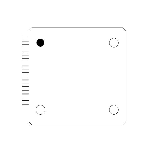
PIN CONFIGURATION (TOP VIEW)
P10-4 |
1 |
|||
P10-5 |
|
|
|
|
TM5EVT/P10-7 |
|
|
|
|
RXD1/P8-0 |
|
|
|
|
TXD1/P8-1 |
5 |
|||
RXC1/P8-2 |
|
|
|
|
TXC1/P8-3 |
|
|
|
|
TM4OUT/P8-4 |
|
|
|
|
PWM2OUT/P8-6 |
|
|
|
|
PWM3OUT/P8-7 |
|
|
10 |
|
|
|
|||
PWM0OUT/P7-6 |
|
|
|
|
|
|
|
|
|
PWM1OUT/P7-7 |
|
|
|
|
|
|
|
|
|
VDD |
|
|
|
|
|
|
|
|
|
GND |
|
|
|
|
HLDACK/P9-7 |
15 |
|||
EXINT4/P9-0 |
|
|
|
|
EXINT5/P9-1 |
|
|
|
|
P9-2 |
|
|
|
|
P9-3 |
|
|
|
|
EXINT0/P6-0 |
20 |
|||
EXINT1/P6-1 |
|
|
|
|
EXINT2/P6-2 |
|
|
|
|
|
|
|
|
|
EXINT3/P6-3 |
|
|
|
|
|
|
|
|
|
P6-4 |
|
|
|
|
|
|
|
|
|
P6-5 |
|
25 |
||
|
||||
P10-3 |
SIOO3/P10-2 SIOI3/P10-1 SIOCK3/P10-0 TM3EVT/P7-5 TM3OUT/P7-4 |
RXC0/P7-2 GND TXD0/P7-1 |
RXD0/P7-0 AGND |
AI7/P12-7 AI6/P12-6 |
AI5/P12-5 AI4/P12-4 AI3/P12-3 |
AI2/P12-2 AI1/P12-1 AI0/P12-0 V |
V A19/P2-3 |
A18/P2-2 A17/P2-1 |
A16/P2-0 |
||||||||||||||||||||||||||||||||||||||||||||||||||
|
|
|
|
|
|
|
|
|
|
|
|
|
|
|
|
|
|
|
|
|
|
|
|
|
|
|
|
|
|
|
|
|
|
|
|
|
|
|
|
|
|
|
|
REF |
DD |
|
|
|
|
|
|
|
|
||||||
|
|
|
|
|
|
|
|
|
|
|
|
|
|
|
|
|
|
|
|
|
|
|
|
|
|
|
|
|
|
|
|
|
|
|
|
|
|
|
|
|
|
|
|
|
|
|
|
|
|
|
|
|
|
|
|
|
|
|
|
100 |
95 |
|
|
|
|
|
|
|
90 |
|
|
|
|
|
85 |
|
|
|
|
|
|
|
|
|
80 |
|
|
|
|
|
|
|
|
|
|
||||||||||||||||||||||||
30 |
|
|
|
35 |
40 |
|
|
|
45 |
50 |
||||||||||||||||||||||||||||||||||||||||||||||||||||
|
|
|
|
|
|
|
|
|
|
|
|
|
|
|
|
|
|
|
|
|
|
|
|
|
|
|
|
|
|
|
|
|
|
|
|
|
|
|
|
|
|
|
|
|
|
|
|
|
|
|
|
|
|
|
|
|
|
|
|
|
|
|
|
|
|
|
|
|
|
|
|
|
|
|
|
|
|
|
|
|
|
|
|
|
|
|
|
|
|
|
|
|
|
|
|
|
|
|
|
|
|
|
|
|
|
|
|
|
|
|
|
|
|
|
|
|
|
|
|
|
|
|
|
|
|
6-P6 7-P6 4/CPCM0-P5 5/CPCM1-P5 6/TM0OUT-P5 |
7/TM0EVT-P5 |
RES NMI |
EA V |
XT0 |
XT1 GND OSC0 |
OSC1 |
V |
0/WAIT-P11 1/HOLD-P11 2/CLKOUT-P11 3/XTOUT-P11 |
6/TM9OUT-P11 7/TM9EVT-P11 |
1/PSEN-P3 |
2/RD-P3 3/WR-P3 |
|||||||||||||||||||||||||||||||||||||||||||||||||||
|
|
|
|
|
|
|
|
|
|
|
|
|
|
|
|
|
|
|
|
|
DD |
|
|
|
|
|
|
|
|
|
|
|
|
|
DD |
|
|
|
|
|
|
|
|
|
|
|
|
|
|
|
|
|
|
|
|
|
|
|
||||
|
|
|
|
|
|
|
|
|
|
|
|
|
|
|
|
|
|
|
|
|
|
|
|
|
|
|
|
|
|
|
|
|
|
|
|
|
|
|
|
|
|
|
|
|
|
|
|
|
|
|
|
|
|
|
|
|
|
|
|
|
|
|
75 
 P1-7/A15

 P1-6/A14

 P1-5/A13

 P1-4/A12
 P1-3/A11 70
  P1-2/A10
  P1-1/A9
  P1-0/A8
  P4-7/A7
  P4-6/A6
65  P4-5/A5

 P4-4/A4

 P4-3/A3

 P4-2/A2
 P4-1/A1 60
  P4-0/A0

 GND
GND

 P0-7/D7

 P0-6/D6
  P0-5/D5 55
  P0-4/D4
  P0-3/D3
  P0-2/D2
  P0-1/D1
  P0-0/D0
100-pin Plastic TQFP
5/28
PEDL66573-02
1Semiconductor |
MSM66573 Family |
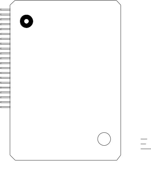
PIN CONFIGURATION (TOP VIEW) (continued)
SIOI3/P10-1 1 SIOO3/P10-2
P10-3
P10-4
P10-5 5 TM5EVT/P10-7
RXD1/P8-0
TXD1/P8-1
RXC1/P8-2 TXC1/P8-3 
 10
10
TM4OUT/P8-4  PWM2OUT/P8-6
  PWM3OUT/P8-7
  PWM0OUT/P7-6 PWM1OUT/P7-7 15
VDD
GND HLDACK/P9-7 EXINT4/P9-0 EXINT5/P9-1 20
P9-2
P9-3  EXINT0/P6-0
  EXINT1/P6-1
  EXINT2/P6-2
  25 EXINT3/P6-3
P6-4 
P6-5 
P6-6 
P6-7  30
30
SIOCK3/P10-0 |
TM3EVT/P7-5 TM3OUT/P7-4 RXC0/P7-2 GND TXD0/P7-1 |
RXD0/P7-0 |
AGND AI7/P12-7 AI6/P12-6 AI5/P12-5 |
AI4/P12-4 AI3/P12-3 AI2/P12-2 AI1/P12-1 AI0/P12-0 |
V |
V A19/P2-3 |
A18/P2-2 |
||||||||||||||||||||||||||||||||||||||||
|
|
|
|
|
|
|
|
|
|
|
|
|
|
|
|
|
|
|
|
|
|
|
|
|
|
|
|
|
|
|
|
|
|
|
|
|
REF |
DD |
|
|
|
||||||
|
|
|
|
|
|
|
|
|
|
|
|
|
|
|
|
|
|
|
|
|
|
|
|
|
|
|
|
|
|
|
|
|
|
|
|
|
|
|
|
|
|
|
|
|
|
|
|
100 |
95 |
|
|
|
90 |
85 |
|
|
|
|
|
|
|
|
|
|
|
||||||||||||||||||||||||||||||
35 |
|
|
|
|
|
|
|
|
40 |
|
|
|
|
|
|
|
|
|
|
|
45 |
50 |
||||||||||||||||||||||||||||
|
|
|
|
|
|
|
|
|
|
|
|
|
|
|
|
|
|
|
|
|
|
|
|
|
|
|
|
|
|
|
|
|
|
|
|
|
|
|
|
|
|
|
|
|
|
|
|
|
|
|
|
|
|
|
|
|
|
|
|
|
|
|
|
|
|
|
|
|
|
|
|
|
|
|
|
|
|
|
|
|
|
|
|
|
|
|
|
|
|
|
|
|
|
|
|
|
|
|
|
|
|
4/CPCM0-P5 5/CPCM1-P5 6/TM0OUT-P5 7/TM0EVT-P5 RES |
NMI |
EA V |
XT0 XT1 |
GND OSC0 OSC1 |
V |
-P110/WAIT |
1/HOLD-P11 2/CLKOUT-P11 3/XTOUT-P11 6/TM9OUT-P11 7/TM9EVT-P11 |
|||||||||||||||||||||||||||||||||||||||||||
|
|
|
|
|
|
|
|
|
|
|
|
|
|
|
|
|
DD |
|
|
|
|
|
|
|
|
|
|
|
|
|
|
DD |
|
|
|
|
|
|
|
|
|
|
|
|
|
|
||||
100-pin Plastic QFP
80  P2-1/A17

 P2-0/A16

 P1-7/A15

 P1-6/A14
 P1-5/A13 75
  P1-4/A12
  P1-3/A11
  P1-2/A10
  P1-1/A9
  P1-0/A8
70 
 P4-7/A7

 P4-6/A6

 P4-5/A5

 P4-4/A4

 P4-3/A3 65
 P4-2/A2
 P4-1/A1
 P4-0/A0

 GND
GND

 P0-7/D7 60
 P0-6/D6
 P0-5/D5
 P0-4/D4
 P0-3/D3
 P0-2/D2 55
  P0-1/D1
  P0-0/D0

 P3-3/WR

 P3-2/RD

 P3-1/PSEN
6/28
PEDL66573-02
1Semiconductor |
MSM66573 Family |
PIN DESCRIPTIONS
In the Type column, “I” indicates an input pin, “O” indicates an output pin, and “I/O” indicates an I/O pin.
Classification |
Symbol |
|
Function |
|
||
Type |
Primary function |
Type |
Secondary function |
|||
|
|
|||||
Port |
P0_0/D0 |
I/O |
8-bit I/O port |
I/O |
External memory access |
|
|
to |
|
10 mA sink capability |
|
Data I/O port |
|
|
P0_7/D7 |
|
Pull-up resistors can be |
|
|
|
|
|
specified for each individual bit |
|
|
||
|
|
|
|
|
||
|
|
|
|
|
|
|
|
P1_0/A8 |
I/O |
8-bit I/O port |
O |
External memory access |
|
|
to |
|
Pull-up resistors can be |
|
Address output port |
|
|
P1_7/A15 |
|
specified for each individual bit |
|
|
|
|
|
|
|
|
||
|
P2_0/A16 |
I/O |
4-bit I/O port |
O |
External memory access |
|
|
to |
|
Pull-up resistors can be |
|
Address output port |
|
|
P2_3/A19 |
|
specified for each individual bit |
|
|
|
|
|
|
|
|
||
|
P3_1/PSEN |
I/O |
3-bit I/O port |
O |
External program memory |
|
|
|
|
10 mA sink capability |
|
access |
|
|
|
|
Pull-up resistors can be |
|
Read strobe output pin |
|
|
P3_2/RD |
|
specified for each individual bit |
O |
External memory access |
|
|
|
|
|
|
Read strobe output pin |
|
|
P3_3/WR |
|
|
O |
External memory access |
|
|
|
|
|
|
Write strobe output pin |
|
|
P4_0/A0 |
I/O |
8-bit I/O port |
O |
External memory access |
|
|
to |
|
Pull-up resistors can be |
|
Address output port |
|
|
P4_7/A7 |
|
specified for each individual bit |
|
|
|
|
|
|
|
|
||
|
P5_4/CPCM0 |
I/O |
4-bit I/O port |
I/O |
Capture 0 input / Compare |
|
|
|
Pull-up resistors can be |
|
0 output pin |
||
|
P5_5/CPCM1 |
|
specified for each individual bit |
I/O |
Capture 1 input / Compare |
|
|
|
|
|
1 output pin |
||
|
P5_6/TM0OUT |
|
|
O |
Timer 0 timer output pin |
|
|
|
|
|
|
|
|
|
P5_7/TM0EVT |
|
|
I |
Timer 0 external event input pin |
|
|
|
|
|
|
|
|
|
P6_0/EXINT0 |
I/O |
8-bit I/O port |
I |
External interrupt 0 input pin |
|
|
|
Pull-up resistors can be |
||||
|
P6_1/EXINT1 |
|
specified for each individual bit |
I |
External interrupt 1 input pin |
|
|
|
|
||||
|
|
|
|
|
|
|
|
P6_2/EXINT2 |
|
|
I |
External interrupt 2 input pin |
|
|
|
|
|
|
|
|
|
P6_3/EXINT3 |
|
|
I |
External interrupt 3 input pin |
|
|
|
|
|
|
|
|
|
P6_4 to P6_7 |
|
|
— |
None |
|
|
|
|
|
|
|
|
7/28
PEDL66573-02
1Semiconductor |
MSM66573 Family |
Classification |
Symbol |
|
Function |
|
|
|
Type |
Primary function |
Type |
Secondary function |
|
||
|
|
|
||||
Port |
P7_0/RXD0 |
I/O |
7-bit I/O port |
I |
SIO0 receive data input pin |
|
Pull-up resistors can be |
|
|||||
|
P7_1/TXD0 |
O |
SIO0 transmit data output pin |
|
||
|
|
specified for each individual bit |
|
|||
|
P7_2/RXC0 |
|
|
I |
SIO0 external clock input pin |
|
|
P7_4/TM3OUT |
|
|
O |
Timer 3 timer output pin |
|
|
P7_5/TM3EVT |
|
|
I |
Timer 3 external event input pin |
|
|
P7_6/PWM0OUT |
|
|
O |
PWM0 output pin |
|
|
P7_7/PWM1OUT |
|
|
O |
PWM1 output pin |
|
|
|
|
|
|
|
|
|
P8_0/RXD1 |
I/O |
7-bit I/O port |
I |
SIO1 receive data input pin |
|
|
|
|
Pull-up resistors can be |
|
|
|
|
P8_1/TXD1 |
|
O |
SIO1 transmit data output pin |
|
|
|
|
specified for each individual bit |
|
|||
|
P8_2/RXC1 |
|
|
I/O |
SIO1 receive clock I/O pin |
|
|
P8_3/TXC1 |
|
|
I/O |
SIO1 transmit clock I/O pin |
|
|
P8_4/TM4OUT |
|
|
O |
Timer 4 timer output pin |
|
|
P8_6/PWM2OUT |
|
|
O |
PWM2 output pin |
|
|
|
|
|
|
|
|
|
P8_7/PWM3OUT |
|
|
O |
PWM3 output pin |
|
|
P9_0/EXINT4 |
I/O |
5-bit I/O port |
I |
External Interrupt 4 input pin |
|
|
|
Pull-up resistors can be |
|
|
||
|
P9_1/EXINT5 |
|
I |
External Interrupt 5 input pin |
|
|
|
|
specified for each individual bit |
|
|||
|
|
|
|
|||
|
P9_2, P9_3 |
|
|
— |
None |
|
|
|
|
|
|
||
|
P9_7/HLDACK |
|
|
O |
HOLD mode output pin |
|
|
|
|
|
|
||
|
P10_0/SIOCK3 |
I/O |
7-bit I/O port |
I/O |
SIO3 transmit-receive clock I/O pin |
|
|
|
Pull-up resistors can be |
|
|
||
|
P10_1/SIOCI3 |
|
I |
SIO3 receive data input pin |
|
|
|
|
specified for each individual bit |
|
|||
|
|
|
|
|||
|
P10_2/SIOO3 |
|
|
O |
SIO3 transmit data output pin |
|
|
|
|
|
|
||
|
P10_3 to P10_5 |
|
|
— |
None |
|
|
|
|
|
|
||
|
P10_7/TM5EVT |
|
|
I |
Timer 5 external event input pin |
|
|
|
|
|
|
||
|
P11_0/WAIT |
I/O |
6-bit I/O port |
I |
External data memory access |
|
|
|
10 mA sink capability |
|
wait input pin |
|
|
|
|
|
|
|
||
|
P11_1/HOLD |
|
Pull-up resistors can be |
I |
HOLD mode request input pin |
|
|
|
specified for each individual bit |
|
|
||
|
P11_2/CLKOUT |
|
O |
Main clock pulse output pin |
|
|
|
|
|
|
|||
|
|
|
|
|
||
|
P11_3/XTOUT |
|
|
O |
Sub clock pulse output pin |
|
|
|
|
|
|
||
|
P11_6/TM9OUT |
|
|
O |
Timer 9 timer output pin |
|
|
|
|
|
|
||
|
|
|
|
|
|
|
|
P11_7/TM9EVT |
|
|
I |
Timer 9 external event input pin |
|
|
|
|
|
|
||
|
P12_0/AI0 |
|
8-bit input port |
|
A/D converter analog input port |
|
|
to |
I |
I |
|
||
|
P12_7/AI7 |
|
|
|
|
|
8/28
PEDL66573-02
1Semiconductor |
MSM66573 Family |
Classification |
Symbol |
Type |
Function |
Power |
VDD |
I |
Power supply pin |
supply |
|
|
Connect all VDD pins to the power supply. |
|
GND |
I |
GND pin |
|
|
|
Connect all GND pins to GND. |
|
VREF |
I |
Analog reference voltage pin |
|
AGND |
I |
Analog GND pin |
Oscillation |
XT0 |
I |
Sub clock oscillation input pin |
|
|
|
Connect to a crystal oscillator of f = 32.768 kHz. |
|
XT1 |
O |
Sub clock oscillation output pin |
|
|
|
Connect to a crystal oscillator of f = 32.768 kHz. |
|
|
|
The clock output is opposite in phase to XT0. |
|
OSC0 |
I |
Main clock oscillation input pin |
|
|
|
Connect to a crystal or ceramic oscillator. Or, input an external |
|
|
|
clock. |
|
OSC1 |
O |
Main clock oscillation output pin |
|
|
|
Connect to a crystal or ceramic oscillator. |
|
|
|
The clock output is opposite in phase to OSC0. |
|
|
|
Leave this pin unconnected when an external clock is used. |
Reset |
RES |
I |
Reset input pin |
Other |
NMI |
I |
Non-maskable interrupt input pin |
|
EA |
I |
External program memory access input pin |
|
|
|
If the EA pin is enabled (low level), the internal program memory is |
|
|
|
masked and the CPU executes the program code in external |
|
|
|
program memory through all address space. |
9/28
 Loading...