


 Loading...
OKIPAGE 6e/6ex LED Page Printer
Maintenance Manual
ODA/OEL/INT
Approval
All specifications are subject to change without notice.
PREFACE
This Maintenance Manual describes the field maintenance methods for OKIPAGE 6e and OKIPAGE 6ex LED Page Printers.
This manual is written for use by service persons. Please note that you should refer to the Printer Handbook for the handling and operating methods of the equipment.

|
|
|
CONTENTS |
|
|
1. |
CONFIGURATION ..................................................................................... |
1 - 1 |
|||
|
1.1 |
System Configuration ........................................................................ |
1 - 1 |
||
|
1.2 |
Printer Configuration .......................................................................... |
1 - 2 |
||
|
1.3 |
Optional Configuration ....................................................................... |
1 - 3 |
||
|
1.4 |
Specification ...................................................................................... |
1 - 5 |
||
|
1.5 |
Safety Standards ............................................................................... |
1 - 7 |
||
|
|
1.5.1 |
Certification Label .................................................................................... |
1 |
- 7 |
|
|
1.5.2 |
Warning Label ......................................................................................... |
1 |
- 8 |
|
|
1.5.3 |
Warning/Caution Marking ........................................................................ |
1 |
- 9 |
2. |
OPERATION DESCRIPTION .................................................................... |
2 - 1 |
|||
|
2.1 |
Control Board..................................................................................... |
2 - 4 |
||
|
2.2 |
PS Board ........................................................................................... |
2 - 6 |
||
|
2.3 |
RAM Board ........................................................................................ |
2 - 7 |
||
|
2.4 |
Power Supply Board .......................................................................... |
2 - 8 |
||
|
2.5 |
Electrophotographic Process ............................................................. |
2 - 10 |
||
|
|
2.5.1 |
Electrophotographic Process Mechanism ............................................... |
2 |
- 10 |
|
|
2.5.2 |
Electrophotographic Process .................................................................. |
2 |
- 13 |
|
|
2.5.3 |
Process Operation Descriptions .............................................................. |
2 |
- 16 |
|
2.6 |
Paper Jam Detection ......................................................................... |
2 - 27 |
||
|
2.7 |
Cover Open ....................................................................................... |
2 - 30 |
||
|
2.8 |
Toner Low Detection.......................................................................... |
2 - 31 |
||
3. |
PARTS REPLACEMENT ........................................................................... |
3 - 1 |
|||
|
3.1 |
Precautions for Parts Replacement ................................................... |
3 - 1 |
||
|
3.2 |
Parts Layout....................................................................................... |
3 - 3 |
||
|
3.3 |
How to Change Parts......................................................................... |
3 - 6 |
||
|
|
3.3.1 |
Upper Cover ............................................................................................ |
3 |
- 7 |
|
|
3.3.2 |
Stacker .................................................................................................... |
3 |
- 8 |
|
|
3.3.3 |
LED Head ................................................................................................ |
3 |
- 9 |
|
|
3.3.4 |
Eject Roller Assy ..................................................................................... |
3 |
- 10 |
|
|
3.3.5 |
Pulse Motor (Main) .................................................................................. |
3 |
- 11 |
|
|
3.3.6 |
Pulse Motor (Registration) ....................................................................... |
3 |
- 12 |
|
|
3.3.7 |
Lower Base Unit ...................................................................................... |
3 |
- 13 |
|
|
3.3.8 |
Motor Assy .............................................................................................. |
3 |
- 14 |
|
|
3.3.9 |
Hopping Roller Assy ................................................................................ |
3 |
- 15 |
|
|
3.3.10 |
Stacker Cover Assy ................................................................................. |
3 |
- 16 |
|
|
3.3.11 |
Registration Roller ................................................................................... |
3 |
- 17 |
|
|
3.3.12 |
Transfer Roller ......................................................................................... |
3 |
- 18 |
|
|
3.3.13 |
Fusing Unit Assy ..................................................................................... |
3 |
- 19 |
|
|
3.3.14 |
Back-up Roller ......................................................................................... |
3 |
- 20 |
|
|
3.3.15 |
Sensor Plate (Inlet) .................................................................................. |
3 |
- 21 |
|
|
3.3.16 |
Toner Sensor (Adhesion) ........................................................................ |
3 |
- 22 |
|
|
3.3.17 |
Sensor Plate (Outlet) ............................................................................... |
3 |
- 23 |
|
|
3.3.18 |
Manual Feed Guide Assy ........................................................................ |
3 |
- 24 |
|
|
3.3.19 |
Sensor Plate (Paper Supply) ................................................................... |
3 |
- 25 |
|
|
3.3.20 |
Main Control PCB .................................................................................... |
3 |
- 26 |
|
|
3.3.21 |
Power Supply Board and Contact Assy .................................................. |
3 |
- 27 |
>>>>>
|
|
3.3.22 |
Transformer ............................................................................................. |
3 |
- 28 |
|
|
|
3.3.23 |
Cassette Guide L ..................................................................................... |
3 |
- 29 |
|
|
|
3.3.24 |
Cassette Guide R .................................................................................... |
3 |
- 30 |
|
4. |
ADJUSTMENT ........................................................................................... |
4 |
- 1 |
|||
|
4.1 |
Adjustment ......................................................................................... |
4 |
- 1 |
||
|
|
4.1.1 |
Maintenance Functions ........................................................................... |
4 |
- 1 |
|
|
4.2 |
Adjustment ......................................................................................... |
4 |
- 10 |
||
|
|
4.2.1 |
Maintenance Modes and Functions ........................................................ |
4 |
- 10 |
|
|
4.3 |
Adjustment When Replacing a Part ................................................... |
4 |
- 12 |
||
|
|
4.3.1 |
Adjustment at the Time of Part Replacement |
|
|
|
|
|
|
(OKIPAGE6e 300dpi LED head) ............................................................. |
4 |
- 12 |
|
|
|
4.3.2 |
Adjustment When Replacing a Part (OKIPAGE6ex 600dpi LED head) .. |
4 |
- 14 |
|
|
|
4.3.3 |
Uploading / Downloading EEPROM data ................................................ |
4 |
- 17 |
|
5. |
PERIODICAL MAINTENANCE ................................................................. |
5 |
- 1 |
|||
|
5.1 |
Periodical Replacement Parts ........................................................... |
5 |
- 1 |
||
|
5.2 |
Cleaning............................................................................................. |
5 |
- 1 |
||
|
|
5.2.1 |
Cleaning of LED Lens Array .................................................................... |
5 |
- 1 |
|
6. |
TROUBLESHOOTING PROCEDURES .................................................... |
6 |
- 1 |
|||
|
6.1 |
Troubleshooting Tips ......................................................................... |
6 |
- 1 |
||
|
6.2 |
Check Points before Correcting Image Problems .............................. |
6 |
- 1 |
||
|
6.3 |
Tips for Correcting Image Problems .................................................. |
6 |
- 1 |
||
|
6.4 |
Preparation for Troubleshooting ........................................................ |
6 |
- 2 |
||
|
6.5 |
Troubleshooting Flow ........................................................................ |
6 |
- 3 |
||
|
|
6.5.1 |
Status Message/Trouble List ................................................................... |
6 |
- 3 |
|
|
|
6.5.2 |
Status Message Troubleshooting ............................................................ |
6 |
- 24 |
|
|
|
6.5.3 |
Image Troubleshooting ............................................................................ |
6 |
- 36 |
|
7. |
WIRING DIAGRAM .................................................................................... |
7 |
- 1 |
|||
|
7.1 |
Interconnect Signal Diagram ............................................................. |
7 |
- 1 |
||
|
7.2 |
PCB Layout and Connector Signal List ............................................. |
7 |
- 3 |
||
|
7.3 |
Resistance Check .............................................................................. |
7 |
- 15 |
||
|
7.4 |
Short Plug Setting .............................................................................. |
7 |
- 17 |
||
8. |
PARTS LIST .............................................................................................. |
8 |
- 1 |
|||
Appendix A |
Centronics Parallel Interface ................................................. |
A - 1 |
||||
|
|
B LocalTalk (RS422) Serial Interface ........................................ |
B - 1 |
|||
|
|
C |
Diagnostics Test..................................................................... |
C - 1 |
||
|
|
D |
Maintenance Utility Overview................................................ |
D - 1 |
||
|
|
E |
Multi-Purpose Feeder Maintenance ...................................... |
E - 1 |
||
|
|
F High Capacity Second Paper Feeder Maintenance ............. |
F - 1 |
|||

1. CONFIGURATION
1.CONFIGURATION
1.1System Configuration
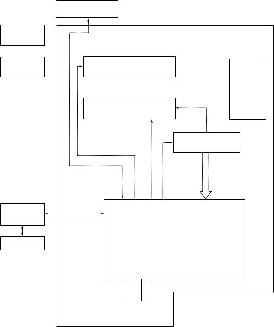
OKIPAGE 6e and OKIPAGE 6ex consist of control and engine blocks in the standard configuration, as shown in Figure 1-1.
In addition, the options marked with asterisk(*) are available.
|
Operator Panel |
|
|
(OKIPAGE 6ex Only) |
|
|
|
Engine Unit |
Paper |
|
|
Cassette |
|
|
* Legal/Universal |
Paper Feed Mechanism |
|
Paper Tray |
(First Tray Unit) |
Face |
|
|
Down |
|
Electrophotographic |
Stacker |
|
Processing Unit |
|
|
|
Power Supply |
|
|
and Sensor PCB |
* Hight Capacity |
Main Control PCB |
|
Second Paper Feeder |
|
|
* Multi-Purpose |
|
|
Feeder |
|
|
*OKIPAGE 6ex |
: PS Board with RAM |
* : Optional |
|
||
*OKIPAGE 6e/6ex |
: RAM Board |
|
|
|
|
Figure 1-1
1 - 1
1.2Printer Configuration
The printer unit consists of the following hardware components:
•Electrophotographic Processor
•Paper Feeder
•Main Control PCB
•Operator Panel (OKIPAGE 6ex Only)
•Power Supply Unit
•PS Board (OKIPAGE 6ex Only)
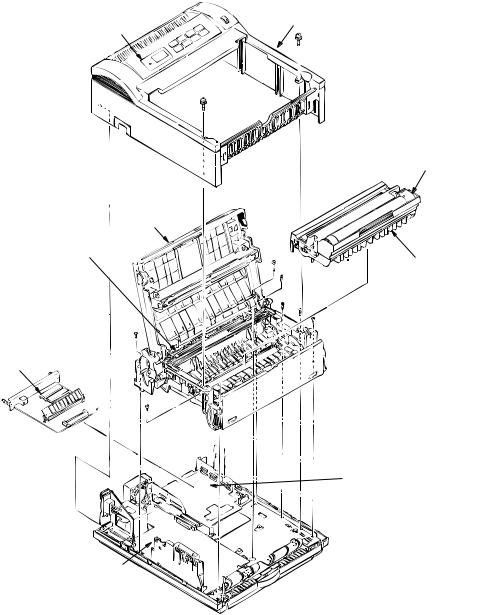
The printer unit configuration is shown in Figure 1-2.
Upper cover
Operator panel assy
Toner cartridge (consumables)
Stacker cover assy 
Fusing unit
Image drum unit (consumable)
PS Board
Main Control PCB |
||
• L5C or L5D: |
OKIPAGE6e |
|
• L6A |
: |
OKIPAGE 6ex |
Power supply board
Figure 1-2
1 - 2
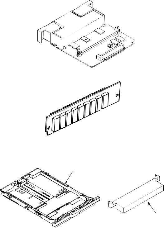
1.3Optional Configuration
The options shown below are available for use with OKIPAGE 6e and OKIPAGE 6ex. These are available separately from the printer unit.
(1) 1MB Memory Expansion Board (OKIPAGE 6e/6ex)
(2)SIMM Memory
OKIPAGE 6e :1/2/4/8/16 Mbyte OKIPAGE 6ex :1/2/4/8/16/32 Mbyte
(3) Legal/Universal Paper Cassette/
Legal/Universal cassette
Cassette cover
1 - 3
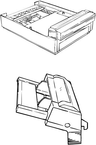
(4) High Capacity Second Paper Feeder
(5) Multi-Purpose Feeder
1 - 4
1.4Specification
(1) |
Type |
Desktop |
|
(2) |
External dimensions |
Height 6.3” |
(160 mm) |
|
(excludes protruding |
Width 12.6” |
(320 mm) |
|
portion) |
Depth 14.17” |
(360 mm) |
(3) |
Weight |
8 kg |
|
(4) |
Developing method |
Dry electrophotography |
|
|
Exposing method |
LED stationary head |
|
(5) |
Paper used |
<Type> |
|
•Standard paper
–Xerox 4200 (20 lbs)
•Application paper (manual face-up feed)
–Label
–Envelope
–OHP paper (Transparency)
<Size>
|
|
• |
Standard sizes |
|
|
|
|
– Letter (ODA) |
|
|
|
|
– Legal (option) |
|
|
|
|
– Executive |
|
|
|
|
– Envelope |
|
|
|
|
– A4 |
|
|
|
|
– A5 |
|
|
|
|
– B5 |
|
|
|
|
– A6 |
|
|
|
• |
Applicable sizes |
|
|
|
|
– Width: |
3.94” to 8.5” (100 to 216 mm) |
|
|
|
– Length: |
5.83” to 14” (148 to 355.6 mm) |
|
|
<Thickness> |
|
|
|
|
|
– Automatic feed: |
16 to 24 lbs (60 to 90 g/m2) |
|
|
|
– Manual feed: |
Label, OHP paper (transparency) |
|
|
|
|
Envelope |
(6) |
Printing speed |
First print: |
17 sec. |
|
|
|
Continuous print: |
6 sheets/min. for letter size paper |
|
|
|
Warm-up time: |
60 sec. [at room temperature 77˚F |
|
|
|
|
|
(25˚C) and rated voltage (120 VAC)] |
(7) |
Paper feeding method |
Automatic feed or manual feed |
||
(8) |
Paper delivery method |
Face down/face up |
|
|
(9) |
Resolution |
300 x 300 dots/inch (OKIPAGE 6e) |
||
|
|
600 x 600 dots/inch (OKIPAGE 6ex) |
||
|
|
600 x 1200 dots/inch (OKIPAGE 6ex) |
||
1 - 5
(10) Power input |
120 VAC +5.5%, –15% |
|
|
|
230 VAC +15 %, –15% |
|
|
(11) Power consumption |
Peak: |
Approx. 420W |
|
|
Typical operation: |
Approx. 160W |
|
|
Idle: |
Approx. 55W |
|
|
Power save mode: |
Approx. 15W |
|
(12) Temperature and humidity |
During operation: |
50 to 90°F (10 to 32°C) |
|
|
In storage: |
14 to 110°F (–10 to 43°C) |
|
(13) Noise |
During operation: |
48 dB (A) or less |
|
|
Standby: |
38 dB (A) or less |
|
(14) Consumables |
Toner cartridge kit |
2,000 (5% duty) |
|
|
Image drum cartridge |
20,000 |
(at continuous printing) |
|
|
15,000 |
(3 pages/job) |
|
|
10,000 |
(1 page/job) |
1 - 6

1.5Safety Standards
1.5.1Certification Label
The safety certification label is affixed to the printer at the location described below.
OKIPAGE 6e |
OKIPAGE 6ex |
230V
1 - 7
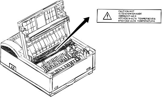
1.5.2Warning Label
The warning labels are affixed to the sections which may cause bodily injury. Follow the instructions on warning labels during maintenance.
1 - 8
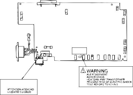
1.5.3Warning/Caution Marking
The following warning and caution markings are made on the power supply board.
 CAUTION
ENGLISH
Heatsink and transformer core present risk of electric shock. Test before touching. FRENCH
Le dissipateur thermique et le noyau du transformateur présentent des risques de choc électrique. Testez avant de, manipuler.
SPANISH
Las disipadores de color el núcel del transformador pueden producir un choque eléctrico. Compruebe antes de tocar.
PORTUGUESE
O dissipador de calor e o núcleo do fransiormador apresentam risco de choque elétrico. Teste antes de focar.
ENGLISH
Circuits maybe live after fuses open.
FRENCH
Il se peut que les circuits soient sous tension une fois que les fusibles ont éfé rerirés.
SPANISH
Las circuitos pueden estar activos una vez que se hayan abierio los fusibles.
PORTUGUESE
Os circuitos podem estar energizados após os fusiveis se queimarem.
1 - 9

2.OPERATION DESCRIPTION
2.OPERATION DESCRIPTION
OKIPAGE 6e, OKIPAGE 6ex consists of a Main Control PCB, a power supply/sensor board, a PostScript board (OKIPAGE 6ex), an operator panel and an electrophotographic process mechanism.
The soft operator panel is used for operation and status display of OKIPAGE 6e and OKIPAGE 6ex.
The operator panel is used for operation and status display of OKIPAGE 6ex.
The OKIPAGE 6e and OKIPAGE 6ex receive data via the host I/F, these then decode, edit and store the data in memory. Bit map image data is successively transferred to the LED head in one dot line units.
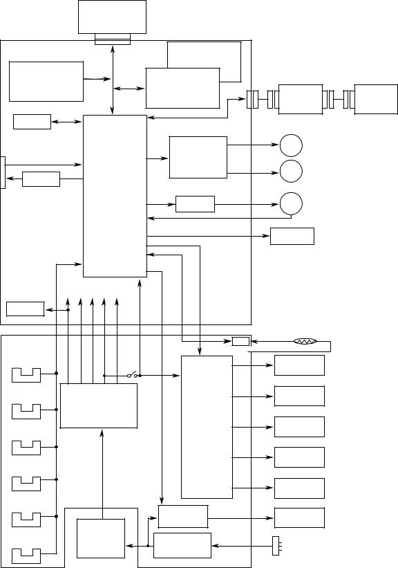
OKIPAGE 6e block diagram is shown in Figure 2-1.
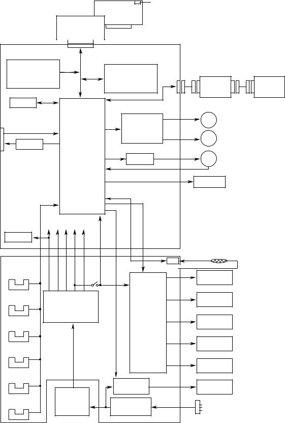
OKIPAGE 6ex block diagram is shown in Figure 2-2.
2 - 1
|
1MB Memory Board |
|
|
|
|
|
|
(Option) |
|
|
|
|
|
L5Cor L5D |
|
For optional |
L5D |
|
|
|
|
|
RAM board |
Resident RAM |
|
|
|
|
|
|
1M x 16 DRAM(2M Bytes) |
|
|
|
Program & Font |
|
L5C |
|
|
|
|
ROM |
|
Resident RAM |
|
|
|
|
4MB Mask ROM |
16 bits |
256k x 16 DRAM x 2 |
High Capacity |
|
||
|
|
(1M Bytes) |
Multi-Purpose |
|||
|
|
Second Paper |
||||
|
DATA |
|
|
Feeder (Option) |
||
|
|
|
Feeder (Option) |
|||
|
BUS |
|
|
|
||
|
|
|
|
|
|
|
EEPROM |
|
|
|
|
|
|
Centronics |
|
|
|
M |
Drum Motor |
|
parallel I/F |
|
|
Drum motor & |
|
||
|
|
|
|
|
||
|
|
|
Registration motor |
|
|
|
|
|
|
drive circuit |
M |
Registration Motor |
|
7407 |
|
|
|
|
||
|
|
|
|
|
|
|
|
1 Chip CPU |
|
|
|
|
|
|
|
|
FAN Driver |
FAN |
|
|
|
|
|
FAN ALM |
|
|
|
|
|
CH TR DB |
LED Head |
|
|
|
|
|
|
|
|
||
|
|
HEAT ON |
|
|
|
|
+8V -8V 0V +5V +30V |
|
|
|
|
||
Reset |
|
|
|
|
|
|
circuit |
|
|
|
|
|
|
|
|
|
LSI |
Thermistor |
|
|
Power Supply |
|
|
|
|
|
|
Board |
|
Cover |
+5V |
|
|
|
|
|
|
|
|
|
|
Inlet sensor 1 |
|
open |
|
Charge roller |
|
|
|
switch |
|
|
|||
|
|
|
|
|
|
|
Inlet sensor 2 |
Low voltage |
|
|
Transfer roller |
|
|
|
|
|
|
|
|
|
|
generation circuit |
|
High voltage |
|
|
|
|
|
|
|
|
|
|
|
|
|
generation |
Developing |
|
|
|
|
|
circuit |
|
||
Paper sensor |
|
|
roller |
|
||
|
|
|
|
|||
|
|
|
|
|
|
|
|
|
|
|
Toner supply |
|
|
|
|
|
|
roller |
|
|
Outlet sensor |
|
|
|
|
|
|
|
|
|
|
Cleaning |
|
|
|
|
|
|
roller |
|
|
Paper out sensor |
|
|
Heater drive |
|
|
|
|
|
|
Heater |
|
||
|
|
|
circuit |
|
||
|
|
|
|
|
|
|
Toner low sensor |
AC |
|
|
|
|
|
transformer |
|
Filter circuit |
AC IN |
|
|
|
|
|
|
|
|
||
Figure 2-1 OKIPAGE 6e Block Diagram
2 - 2
|
|
or |
LocalTalk I/F (RS422 I/F) |
|
|
|
|
|
|
|
|
|
|
|
|
PS Board with RAM |
|
|
|
|
|
1MB Memory Board |
|
|
|
|
|
L6A- |
|
For optional |
|
|
|
|
|
RAM board |
|
|
|
||
|
|
|
|
|
||
|
|
16 bit |
|
|
|
|
Program & Font |
32 bit |
|
Resident RAM |
|
|
|
ROM |
|
|
|
|
|
|
4MB Mask ROM |
DATA |
|
1M x 16 DRAM |
High Capacity |
|
|
|
16 bit |
(2MB) |
Multi-Purpose |
|||
|
Second Paper |
|||||
|
BUS |
|
|
Feeder (Option) |
Feeder (Option) |
|
|
|
|
|
|
||
EEPROM |
|
|
|
|
|
|
Centronics |
|
|
|
M |
Drum Motor |
|
parallel I/F |
|
|
Drum motor & |
|
||
|
|
|
|
|
||
|
|
|
Registration motor |
|
|
|
|
|
|
drive circuit |
M |
Registration Motor |
|
7407 |
|
|
|
|
||
|
|
|
|
|
|
|
|
1 Chip CPU |
FAN Driver |
FAN |
|
|
|
|
|
|
|
|
||
|
|
|
FAN ALM |
|
|
|
|
|
|
CH TR DB |
LED Head |
|
|
|
|
|
|
|
|
|
|
|
|
HEAT ON |
|
|
|
+8V -8V 0V +5V +30V |
|
|
|
|
||
Reset |
|
|
|
|
|
|
circuit |
|
|
|
|
|
|
|
|
|
|
Thermistor |
|
|
Power Supply |
|
|
|
LSI |
|
|
Board |
|
Cover |
|
+5V |
|
|
Inlet sensor 1 |
|
open |
|
Charge roller |
|
|
|
switch |
|
|
|||
|
|
|
|
|||
|
|
|
|
|
|
|
Inlet sensor 2 |
Low voltage |
|
|
Transfer roller |
|
|
|
|
|
|
|
|
|
|
generation circuit |
High voltage |
|
|
|
|
|
|
|
|
|
|
|
|
|
|
generation |
Developping |
|
|
|
|
|
circuit |
|
||
Paper sensor |
|
|
roller |
|
||
|
|
|
|
|||
|
|
|
|
|
|
|
|
|
|
|
Toner supply |
|
|
|
|
|
|
roller |
|
|
Outlet sensor |
|
|
|
|
|
|
|
|
|
|
Cleaning |
|
|
|
|
|
|
roller |
|
|
Paper out sensor |
|
|
Heater drive |
|
|
|
|
|
|
Heater |
|
||
|
|
|
circuit |
|
||
|
|
|
|
|
|
|
Toner low sensor |
AC |
|
|
|
|
|
transformer |
Filter circuit |
AC IN |
|
|
||
|
|
|
|
|
||
Figure 2-2 OKIPAGE 6ex Block Diagram
2 - 3
2.1Control Board
The control board consists of a single chip CPU, Program & Font ROM's, one or two DRAMs, an EEPROM, a host interface circuit, and a mechanism driving circuit.
(1)Single chip CPU
The single chip CPU is a custom CPU (32-bit internal bus, 16-bit or 32-bit external bus, 25.54 MHz clock with input frequency from a 12.27 MHz clock) which incorporates the RISC CPU and its peripheral devices, and has the following functions:
Built-in device |
Function |
|
|
Chip select controller |
Control of ROM, DRAM and I/O device |
Bus controller |
|
DRAM controller |
|
|
|
DMA controller |
Transfer of image data from DRAM to video output port |
|
|
Parallel interface controller |
Control of Centronics parallel interface |
|
|
Video output port |
Control of LED head |
LED STB output port |
|
|
|
Timer |
Generation of various control timing |
|
Monitoring of paper running and paper size |
|
|
Serial I/O port |
Control of operator panel, EEPROM, and options |
|
|
I/O port |
Input and output of sensor and motor signals |
|
|
(2)Program & Font ROM OKIPAGE 6e/6ex
The Program & Font ROM store the PCL5e emulation program and various types of fonts. Mask ROM is used for a Program & Font ROM. The mounting location of this Program & Font ROM varies depending on the type of ROM (for the mounting location see 7.2).
PS Board
The Program & Font ROM store the PostScript program and various types of fonts. Mask ROM is used for a Program & Font ROM (for the mounting location see 7.3).
2 - 4
(3)DRAM OKIPAGE 6e/6ex
The DRAM is a resident memory (OKIPAGE 6e: 1MB(L5C) or 2MB(L5D)/OKIPAGE 6ex: 2MB) used as a buffer, and it stores edited data, image data, DLL data and macro data.
OKIPAGE 6ex with PS Board
The DRAM is a resident memory (2MB on the OKIPAGE 6ex main board plus 0.5MB on the PS board) used as a buffer, and it stores edited data, image data, DLL data and macro data. In the Post Script emulation, it is used as VM and font cache also.
(4)EEPROM
1,024 bit-Electrically Erasable PROM (EEPROM), is loaded with the following kinds of data:
•Menu data
•Various counter data (Page counter, Drum counter)
•Adjusting parameters (LED head drive time, print start position, paper feed length)
(5)Parallel Interface
Parallel data is received from the host system via parallel interface which conforms to the Centronics specification. IEEE 1284 Bi-directional parallel is supported.
2 - 5
2.2PS Board (OKIPAGE 6ex option)
The PS board consists of two Program & Font ROM's, DRAM's, an EEPROM, and a host interface circuit.
(1)Program & Font ROM's
The Program & Font ROMs store the PostScript Level II program and its fonts. Mask ROM is used for the Program & Font ROMs.
(2)DRAM
0.5MB of DRAM's reside on the PS board.
(3)EEPROM
4.096 bit-Electrically Erasable PROM (EEPROM) is mounted on the PS board for storing the PostScript's menu settings.
(4)Local Talk I/F
Apple Talk protocol data is received from the host system via LocalTalk interface. The block diagram is shown in Figure 2-3.
(5)SIMM Socket
One SIMM Socket is mounted on the PS board.
|
|
|
|
|
|
|
|
|
|
|
Program & Font |
|
|
Resident RAM |
|
||
|
|
ROM |
|
|
|
|||
|
|
|
|
(0.5MB) |
|
|||
|
|
4MB Mask ROM |
|
|
|
|||
|
|
|
|
|
|
|
||
|
|
|
|
|
|
|
|
|
|
|
|
|
|
|
|
|
|
|
|
|
|
|
|
|
|
|
|
|
|
|
|
|
|
|
|
|
|
|
|
|
|
|
|
|
LocalTalk I/F
(RS422 I/F)
|
|
|
|
|
|
|
|
|
|
|
|
|
|
|
|
|
|
|
|
|
|
|
|
|
|
|
|
|
|
|
|
|
|
|
|
|
|
|
|
|
|
|
|
SCC |
|
SIMM |
|
EEPROM |
|
|
|
|
|
|
|
|
|
|
|
|
|
Socket |
|
(4K) |
|
||
|
|
|
|
|
|
|
|
|
|
85C30 |
|
|
|
|||
|
|
|
|
|
|
|
|
|
|
|
|
|
|
|
|
|
|
|
|
|
|
|
|
|
|
|
|
|
|
|
|
|
|
|
|
|
|
|
|
|
|
|
|
|
|
|
|
|
|
|
|
|
|
|
|
|
|
|
|
|
|
|
|
|
|
|
|
|
|
|
|
|
|
|
|
|
|
|
|
|
|
|
|
|
Figure 2-3 PS Board Block Diagram
2 - 6

2.3RAM Board (OKIPAGE 6e/6ex option)
The RAM board consists of DRAM's and a SIMM socket.
(1)DRAM
1MB of DRAM's reside on the RAM board.
(2)SIMM Socket
One SIMM socket is mounted on the RAM board.
|
SIMM Socket |
|
Resident RAM |
|
||
|
|
|
|
(1MB) |
|
|
|
|
|
|
|
|
|
|
|
|
|
|
|
|
|
|
|
|
|
|
|
|
|
|
|
|
|
|
Figure 2-4 RAM Board Block Diagram
2 - 7
2.4Power Supply Board
The power supply board consists of an AC filter circuit, a low voltage power supply circuit, a high voltage power supply circuit, heater drive circuit, and photosensors.
(1)Low Voltage Power Supply Circuit
This circuit generates the following voltages.
Output voltage |
Use |
|
|
+5 V |
Logic circuit supply voltage |
|
|
+30 V |
Motor and fan drive voltage and source voltage for high-voltage supply |
|
|
+8 V |
Analog supply voltage |
|
|
–8 V |
PS board and analog circuit supply voltage |
|
|
(2)High Voltage Power Supply Circuit
This circuit generates following voltages required for electrophotographic process from +5 V, according to the control sequence from the control board. When cover open state is detected, +5 V supply is interrupted automatically to stop the supply of all high-voltage outputs.
Output |
|
Voltage |
Use |
Remarks |
|
|
|
|
|
CH |
-1.35 KV |
Voltage applied to charging roller |
|
|
|
|
|
|
|
DB |
-300 |
V/+300 V |
Voltage applied to developing roller |
|
|
|
|
|
|
SB |
-450 |
V/ 0 V |
Voltage applied to toner supply roller |
|
|
|
|
|
|
TR |
+500 |
V to +4 KV/-750 V |
Voltage applied to transfer roller |
Variable |
|
|
|
|
|
CB |
+400 |
V |
Voltage applied to clearing roller |
|
|
|
|
|
|
(3)Photosensor
The photosensor mounted on this power supply board monitors the paper running state during printing.
2 - 8
The sensor layout diagram is shown in Figure 2-3.
Paper running direction
Exit roller
Outlet sensor
Heat roller
|
|
Transfer roller |
|
|
|
Paper sensor |
|
|
|
Inlet sensor 1 |
|
Toner |
Inlet |
Paper |
|
end sensor |
Registration roller |
||
sensor |
sensor 2 |
Hopping |
|
|
|
|
|
|
|
roller |
|
Figure 2-5
Sensor |
Function |
|
Sensing state |
|
|
|
|
Inlet sensor 1 |
Detects the leading edge of the paper and gives |
ON: |
Paper exists. |
|
the supervision timing for switching from |
OFF: |
No paper exists. |
|
hopping operation to feeding operation. |
|
|
|
Monitors paper feeding situation and paper size |
|
|
|
based on the paper arrival time and running |
|
|
|
time. |
|
|
|
|
|
|
Inlet sensor 2 |
Detects the form width. |
ON: |
A4 or larger |
|
|
OFF: |
Smaller than A4 |
|
|
|
|
Paper sensor |
Detects the leading portion of the paper. |
ON: |
Paper exists. |
|
Monitors the paper feeding situation. |
OFF: |
No paper exists. |
|
|
|
|
Outlet sensor |
Monitors the paper feeding and size according |
ON: |
Paper exists. |
|
to the time of arrival to and leaving past the |
OFF: |
No paper exists. |
|
sensor. |
|
|
|
|
|
|
Paper end sensor |
Detects the end of the paper. |
ON: |
Paper exists. |
|
|
OFF: |
No paper exists. |
|
|
|
|
Toner low sensor |
Detects the lack of toner. |
- - - - - |
|
|
|
|
|
2 - 9
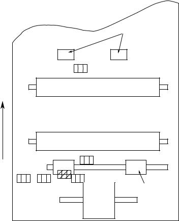
2.5Electrophotographic Process
2.5.1Electrophotographic Process Mechanism
This mechanism actuates the printing of image data supplied by the control board on the paper by electrophotographic process.
The layout of the electrophotographic process mechanism is shown in Figure 2-6.
2 - 10
Heat roller |
LED head |
Developing roller |
Toner cartridge |
Eject roller assy |
|
||
Charge roller |
|
||
|
|
||
|
Image drum unit |
|
|
|
|
|
11 - 2 |
2 Figure |
|
6- |
Outlet sensor lever |
Back-up roller |
|
Hopping roller |
|
|
Registration |
|
|
Cleaning roller |
|
|
Paper cassette |
roller |
|
|
|
|
||
|
Transfer roller |
Inlet sensor lever |
|
|
Paper sensor lever |
|
|
|
|
|
(1)Image Drum Unit
The image drum unit consists of a sensitive drum, a charger, and a developer. The unit forms a toner image on the sensitive drum, using a electrostatic latent image formed by the LED head.
(2)Registration Motor
The registration motor is a pulse motor of 48 steps/rotation, that is two-phase excited by the signal from the Main Control PCB. It drives the hopping and registration rollers via two oneway clutches according to the direction of rotation.
(3)Drum Motor
The drum motor is a pulse motor of 48 steps/rotation that is two-phase excited by the signal from the Main Control PCB and is the main motor of this mechanism.
(4)LED Head
Image data for each dot line from the control board is received by the shift register and latch register. The 2496 LED's (OKIPAGE 6e)/4992 LED's (OKIPAGE 6ex) are driven to radiate the image data on the image drum.
(5)Fuser
The fuser consists of a heater, a heat roller, a thermistor and a thermostat.
The AC voltage from the power supply board is applied to the heater controlled by the HEATON signal from the control board. This AC voltage heats the heater. The Main Control
PCB monitors the heat roller temperature via the thermistor, and regulates the heater roller to a predetermined temperature (165°C) by connecting or disconnecting the AC voltage supply to the heater.
When an abnormal rise of the heater roller temperature takes place, the thermostat of the heater voltage supply circuit becomes active and forcibly cuts the AC voltage supply.
2 - 12
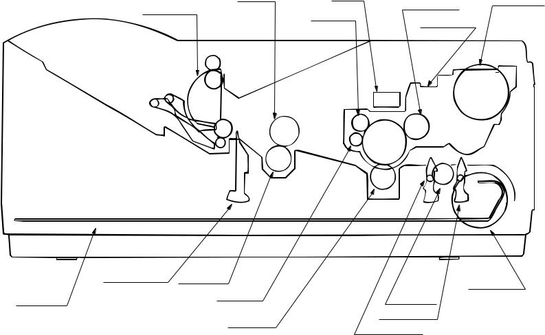
2.5.2Electrophotographic Process
The electrophotographic processing is outlined below. The electrophotographic printing process is shown in Figure 2-7.
1 Charging
The surface of the image drum is charged uniformly with a negative charge by applying the negative voltage to the charge roller.
2Exposure
Light emitted from the LED head irradiates the negatively charged surface of the image drum. The surface potential of the irradiated portion of the image drum surface becomes lower, forming the electrostatic latent image associated with the print image.
3Developing and toner recovery
When the negatively charged toner is brought into contact with the image drum, it is attracted to the electrostatic latent image by static electricity, making the image visible.
At the same time, the residual toner on the image drum is attracted to the developing roller by static electricity.
4 Transfer
When paper is placed over the image drum surface, the positive charge which is opposite in polarity to that of the toner, is applied to the reverse side by the transfer roller. The toner is attracted by the positive charge and is transferred onto the paper. This results in the transfer of the toner image formed on the image drum onto the paper.
5Temporary cleaning
Residual toner which remains on the image drum without being transferred is evened out by the cleaning roller and is temporarily attracted to the cleaning roller by static electricity.
6Fusing
The toner image transferred onto the paper is fused to the paper by heat and pressure.
An electrophotographic process timing chart is shown in Figure 2-8.
2 - 13
14 - 2 |
2 Figure |
|
7- |
Paper eject roller
|
|
Paper |
|
Image data |
|
|
|
|
|
eject |
|
|
|
|
|
|
|
(Face down) |
|
|
|
|
|
|
|
Power |
|
LED head |
|
|
|
|
|
supply |
|
|
|
|
|
|
|
|
|
|
|
|
|
|
|
Charger |
|
|
|
|
|
|
|
roller |
|
|
|
|
|
Paper |
|
|
|
|
|
Power |
|
eject |
|
Power |
|
Exposure |
Doctor |
supply |
Toner |
roller |
|
|
blade |
(Bias voltage) |
cartridge |
||
|
supply |
|
|
|
|||
|
|
|
|
|
|
|
|
|
Paper |
|
Charging |
|
|
|
|
|
|
|
|
|
|
|
|
Paper |
path |
Cleaning |
|
|
Developing |
Toner |
|
selector |
roller |
Cleaning |
Developing |
roller |
supply |
|
|
eject |
|
roller |
|
(Face up)
Outlet sensor |
Fusing |
|
|
|
Paper sensor |
Inlet sensor |
|
|
|
|
|
|
|
|
|
|
|
||
|
|
|
|
|
|
|
|
Paper |
|
|
|
|
|
Transfer |
|
Paper |
|
Paper |
|
|
|
|
|
|
registration |
|
supply |
tray |
|
|
|
|
|
|
|
|
|||
Heater roller |
Back-up roller |
Power |
Transfer |
|
Registration roller |
Hopping |
|
||
supply |
roller |
|
roller |
|
|||||
|
|
|
|
|
|
|
|||
Paper eject |
Fusing |
Cleaning |
|
Transfer |
Image |
Paper feed |
|
Paper hopping |
|
|
production |
|
|
||||||
|
|
|
|
|
developing |
|
|
|
|
Path of paper feeding
Direction of rotation of the image drum
15 - 2 |
2 Figure |
|
8- |
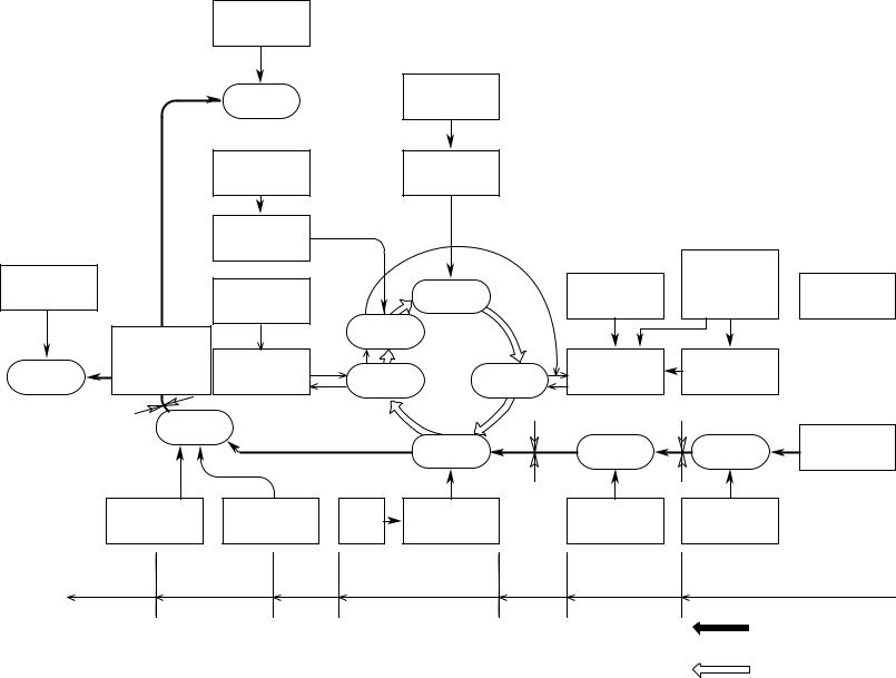
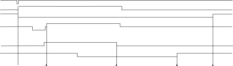
PRINT-N
PRDY-N DM-ON-N
RM-ON
INSNS
OUTSNS-N
Feed start |
Inlet Sensor OFF |
Outlet Sensor OFF |
Feed stop |
Loading...