


OKI MSM66201-xxxSS, MSM66201-xxxGSBK, MSM66207-xxxSS, MSM66207-xxxGSBK, MSM66P207-xxxSS Datasheet
...E2E1027-27-Y4
This version: Jan. 1998
Semiconductor MSM66201/66P201/66207/66P207
¡ Semiconductor
Previous version: Nov. 1996
MSM66201/66P201/66207/
66P207
OLMS-66K Series 16-Bit Microcontroller
GENERAL DESCRIPTION
The MSM66201/66207 is a high performance microcontroller that employs OKI original nX-8/ 200 CPU core. This chip includes a 16-bit CPU, ROM, RAM, I/O ports, multifunction 16-bit timers, 10-bit A/D converter, serial I/O port, and pulse width modulator (PWM). The MSM66P201/66P207 is the OTP (One-Time Programmable) version of the MSM66201/66207.
FEATURES
•64K address space for program memory
•64K address space for data memory
•High-speed execution
Minimum cycle for instruction
•Powerful instruction set
•Abundant addressing modes
•I/O port
Input-output port
Input port
•Built-in multifunctional 16-bit timer Following 4 modes can be set for each timer
•Serial port
•16-bit pulse width modulator
•Watchdog timer
•Transition detector
•10-bit A/D converter
•Interrupts
Nonmaskable Maskable
• Stand-by function STOP mode HALT mode HOLD mode
: Internal ROM : MSM66201 |
16K bytes |
MSM66207 |
32K bytes |
: Internal RAM : MSM66201 |
512 bytes |
MSM66207 |
1024 bytes |
:400ns @ 10MHz
:Instruction set superior in orthogonal matrix 8/16-bit data transfer instructions
8/16-bit arithmetic instructions Multiplication and division operation instructions Bit manipulation instructions
Bit logic instrucitons
ROM table reference instructions
:Register addressing Page addressing
Pointing register indirect addressing Stack addressing
Immediate value addressing
:5 ports ´ 8 bits
(Each bit can be assigned to input or output)
:1 port ´ 8 bits
:4
:Auto-reload timer mode Clock output mode Capture register mode Real time output mode
:1 channel (Synchronous/UART switchable mode with baud rate generators)
:2
:4
:8 channels
:1
:Internal 16/external 2
:Software clock stop mode
:Software CPU stop mode
:Hardware CPU stop mode
1/30
¡ Semiconductor |
MSM66201/66P201/66207/66P207 |
• Package |
: (MSM66201-´´´SS) (MSM66P201-´´´SS) |
64-pin plastic shrink DIP (SDIP64-P-750-1.78) |
|
|
(MSM66207-´´´SS) (MSM66P207-´´´SS) |
64-pin plastic QFP (QFP64-P-1414-0.80-BK) |
: (MSM66201-´´´GSBK)(MSM66207´´´GS- |
|
BK) |
68-pin plastic QFJ (PLCC) (QFJ68-P-S950-1.27) |
: (MSM66201-´´´JS) (MSM66P201-´´´JS) |
|
(MSM66207-´´´JS) (MSM66P207-´´´JS) |
64-pin ceramic piggyback (ADIP64-C-750-1.78) : (MSM66G207VS)
(´´´ indicates the code number.)
*The piggyback type is used only for engineering samples.
2/30

P4.0/TM0CK
P4.1/TM1CK
P3.4/TM0IO
P3.7/TM3IO
P3.1/RXD
P3.0/TXD
P2.7/RXC
P2.6/TXC
P4.4/TRNS0
P4.7/TRNS3
VREF
P5.0/AI 0
P5.7/AI 7
AGND
P4.2/PWM0
P4.3/PWM1
NMI
P3.2/INT0
P3.3/INT1
P2.3/CLKOUT
RESOUT
3/30
TIMER 0–3
SERIAL
PORT
TRANSI-
TION D.
A/D
CONV.
PWM 0,1
INTERRUPT
CONT.
PERIPHERAL
CONT.
WDT
SSP |
LRB |
PSW
ALU
ALU CONT.
ACCUMULATOR
TEMPORARY R. INSTRUCTION CONSTANTS
DECODER
MEMORY
CONT.
PC
RAP
IR
*2
RAM 1024 ´ 8 bits
*1
ROM 32K ´ 8 bits
B U S
P O R T
C O N
T
.
EA
READY  ALE
ALE
 PSEN
PSEN
 RD
RD
 WR
WR
AD0/P0.0
AD7/P0.7
A8 /P1.0
A15/P1.7
DIAGRAM BLOCK
|
|
|
|
|
SYSTEM |
|
|
|
|
|
PORT |
|
*1 MSM66201 16K ´ 8 |
||||
|
|
|
|
|
|
CONTROLLER |
|
|
|
|
|
*2 MSM66201 512 ´ 8 |
|||||
|
|
|
|
|
|
|
|
|
|
|
|
|
|
|
|
|
|
DD |
GND |
FLT RES OSC1 OSC0 |
5.HLDA/P2 4.HOLD/P2 |
P0 |
P1 |
P2 |
P3 |
P4 |
P5 |
||||||||
V |
|
|
|
|
|
|
|
|
|
|
|
|
|
|
|
|
|
Semiconductor ¡
MSM66201/66P201/66207/66P207

¡ Semiconductor |
MSM66201/66P201/66207/66P207 |
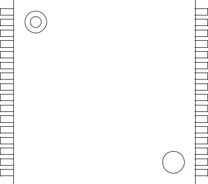
PIN CONFIGURATION (TOP VIEW)
|
|
|
|
|
AD0/P0.0 |
1 |
|
64 |
VDD |
AD1/P0.1 |
|
|
|
VREF |
2 |
63 |
|||
AD2/P0.2 |
|
|
|
AGND |
3 |
62 |
|||
AD3/P0.3 |
|
|
|
P5.7/AI7 |
4 |
61 |
|||
AD4/P0.4 |
|
|
|
P5.6/AI6 |
5 |
60 |
|||
AD5/P0.5 |
|
|
|
P5.5/AI5 |
6 |
59 |
|||
AD6/P0.6 |
|
|
|
P5.4/AI4 |
7 |
58 |
|||
AD7/P0.7 |
|
|
|
P5.3/AI3 |
8 |
57 |
|||
A8/P1.0 |
|
|
|
P5.2/AI2 |
9 |
56 |
|||
A9/P1.1 |
|
|
|
P5.1/AI1 |
10 |
|
55 |
||
A10/P1.2 |
|
|
|
P5.0/AI0 |
11 |
54 |
|||
A11/P1.3 |
|
|
|
P4.7/TRNS3 |
12 |
53 |
|||
A12/P1.4 |
|
|
|
P4.6/TRNS2 |
13 |
52 |
|||
A13/P1.5 |
|
|
|
P4.5/TRNS1 |
14 |
51 |
|||
A14/P1.6 |
|
|
|
P4.4/TRNS0 |
15 |
50 |
|||
A15/P1.7 |
|
|
|
P4.3/PWM1 |
16 |
49 |
|||
P2.0 |
|
|
|
P4.2/PWM0 |
17 |
48 |
|||
P2.1 |
|
|
|
P4.1/TM1CK |
18 |
47 |
|||
P2.2 |
|
|
|
P4.0/TM0CK |
19 |
46 |
|||
CLKOUT/P2.3 |
|
|
|
|
20 |
|
45 |
P3.7/TM3IO |
|
RESOUT |
|
|
|
P3.6/TM2IO |
21 |
|
44 |
||
|
|
|
|
|
ALE |
22 |
|
43 |
P3.5/TM1IO |
PSEN |
|
|
|
|
23 |
|
42 |
P3.4/TM0IO |
|
RD |
|
|
|
P3.3/INT1 |
24 |
|
41 |
||
WR |
|
|
|
P3.2/INT0 |
25 |
|
40 |
||
READY |
|
|
|
P3.1/RXD |
26 |
|
39 |
||
EA |
|
|
|
P3.0/TXD |
27 |
|
38 |
||
FLT |
|
|
|
P2.7/RXC |
28 |
|
37 |
||
RES |
|
|
|
P2.6/TXC |
29 |
|
36 |
||
OSC0 |
|
|
|
P2.5/HLDA |
30 |
|
35 |
||
OSC1 |
|
|
|
P2.4/HOLD |
31 |
|
34 |
||
GND |
|
|
|
NMI |
32 |
|
33 |
||
|
|
|
|
|
64-Pin Plastic Shrink DIP
4/30
¡ Semiconductor |
MSM66201/66P201/66207/66P207 |
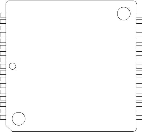
PIN CONFIGURATION (TOP VIEW) (Continued)
A8/P1.0 1
A9/P1.1 2
A10/P1.2 3
A11/P1.3 4
A12/P1.4 5
A13/P1.5 6
A14/P1.6 7
A15/P1.7 8
P2.0 9
P2.1 10
P2.2 11 CLKOUT/P2.3 12 RESOUT 13 ALE 14
PSEN 15
RD 16
|
P0.7/AD7 |
|
P0.6/AD6 |
|
P0.5/AD5 |
|
P0.4/AD4 |
|
P0.3/AD3 |
|
P0.2/AD2 |
|
P0.1/AD1 |
|
P0.0/AD0 |
|
V |
|
V |
|
AGND |
|
P5.7/AI7 |
|
P5.6/AI6 |
|
P5.5/AI5 |
|
P5.4/AI4 |
|
P5.3/AI3 |
|
|
|
|
|
|
|
|
|
|
|
|
|
|
|
|
|
|
DD |
|
REF |
|
|
|
|
|
|
|
|
|
|
|
|
|
|
64 |
|
63 |
|
62 |
|
61 |
|
60 |
|
59 |
|
58 |
|
57 |
|
56 |
|
55 |
|
54 |
|
53 |
|
52 |
|
54 |
|
50 |
|
49 |
|
|
|
|
|
|
|
|
|
|
|
|
|
|
|
|
|
|
|
|
|
|
|
|
|
|
|
|
|
|
|
|
|
|
|
17 |
|
18 |
|
19 |
|
20 |
|
21 |
|
22 |
|
23 |
|
24 |
|
25 |
|
26 |
|
27 |
|
28 |
|
29 |
|
30 |
|
31 |
|
32 |
|
|
|
|
|
|
|
|
|
|
|
|
|
|
|
|
|
|
|
|
|
|
|
|
|
|
|
|
|
|
|
|
|
|
WR |
|
READY |
EA |
FLT |
RES |
|
OSC0 |
OSC1 |
|
GND |
NMI |
|
HOLD/P2.4 |
|
HLDA/P2.5 |
|
TXC/P2.6 |
|
RXC/P2.7 |
|
TXD/P3.0 |
|
RXD/P3.1 |
INT0/P3.2 |
|
|||||||
64-Pin Plastic QFP
48 P5.2/AI2
47 P5.1/AI1
46 P5.0/AI0
45 P4.7/TRNS3
44 P4.6/TRNS2
43 P4.5/TRNS1
42 P4.4/TRNS0
41 P4.3/PWM1
40 P4.2/PWM0
39 P4.1/TM1CK
38 P4.0/TM0CK
37 P3.7/TM3IO
36 P3.6/TM2IO
35 P3.5/TM1IO
34 P3.4/TM0IO
33 P3.3/INT1
5/30
¡ Semiconductor |
MSM66201/66P201/66207/66P207 |
PIN CONFIGURATION (TOP VIEW) (Continued)
AI3/P5.3 61 AI4/P5.4 62 AI5/P5.5 63 AI6/P5.6 64 AI7/P5.7 65
AGND 66
VREF 67
VDD 68
VDD 1 AD0/P0.0 2 AD1/P0.1 3 AD2/P0.2 4 AD3/P0.3 5 AD4/P0.4 6 AD5/P0.5 7 AD6/P0.6 8 AD7/P0.7 9
P5.2/AI2 |
|
P5.1/AI1 |
|
P5.0/AI0 |
|
P4.7/TRNS3 |
|
P4.6/TRNS2 |
|
P4.5/TRNS1 |
|
P4.4/TRNS0 |
|
P4.3/PWM1 |
|
P4.2/PWM0 |
|
P4.1/TM1CK |
|
P4.0/TM0CK |
|
NC |
|
P3.7/TM3IO |
|
P3.6/TM2IO |
|
P3.5/TM1IO |
|
P3.4/TM0IO |
P3.3/INT1 |
|
|
|
|
|
|
|
|
|
|
|
|
|
|
|
|
|
|
|
|
|
|
|
|
|
|
|
|
|
|
|
|
|
|
60 |
|
59 |
|
58 |
|
57 |
|
56 |
|
55 |
|
54 |
|
53 |
|
52 |
|
51 |
|
50 |
|
49 |
|
48 |
|
47 |
|
46 |
|
45 |
|
44 |
10 |
|
11 |
|
12 |
|
13 |
|
14 |
|
15 |
|
16 |
|
17 |
|
18 |
|
19 |
|
20 |
|
21 |
|
22 |
|
23 |
|
24 |
|
25 |
|
26 |
A8/P1.0 |
|
A9/P1.1 |
|
A10/P1.2 |
|
A11/P1.3 |
|
A12/P1.4 |
|
A13/P1.5 |
|
A14/P1.6 |
|
A15/P1.7 |
|
NC |
|
P2.0 |
|
P2.1 |
|
P2.2 |
|
CLKOUT/P2.3 |
|
RESOUT |
|
ALE |
PSEN |
|
RD |
|
NC : No-connection pin
68-Pin Plastic QFJ (PLCC)
43 P3.2/INT0
42 P3.1/RXD
41 P3.0/TXD
40 P2.7/RXC
39 P2.6/TXC
38 P2.5/HLDA
37 P2.4/HOLD
36 NMI
35 GND
34 GND
33 OSC1
32 OSC0
31 RES
30 FLT
29 EA
28 READY
27 WR
6/30

¡ Semiconductor MSM66201/66P201/66207/66P207
PIN DESCRIPTION
Symbol |
Type |
Description |
|
|
|
|
|
P0.0–P0.7/ |
I/O |
P0: 8-bit input-output port. Each bit can be assigned to input or output. |
|
AD0–AD7 |
|
AD: Outputs the lower 8 bits of program counter during external program memory fetch, |
|
|
|
and receives the addressed instruction under the control of PSEN. This pin also |
|
|
|
outputs the address and outputs or inputs data during an external data memory |
|
|
|
access instruction, under the control of ALE, RD, and WR. |
|
|
|
|
|
P1.0–P1.7/ |
I/O |
P1: 8-bit input-output port. Each bit can be assigned to input or output. |
|
A8–A15 |
|
A: Outputs the upper 8 bits of program counter (PC8–15) during external program |
|
|
|
memory fetch. This pin also outputs the upper 8 bits of address during external |
|
|
|
data memory access instructions. |
|
|
|
|
|
P2.0–P2.2 |
I/O |
P2: 8-bit input-output port. Each bit can be assigned to input or output. |
|
P2.3/CLKOUT |
|
CLKOUT: Output pin for supplying a clock to peripheral circuits. |
|
P2.4/HOLD |
|
HOLD: Input pin to request the CPU to enter the hardware power-down state. |
|
P2.5/HLDA |
|
HLDA: HOLD ACKNOWLEDGE: the HLDA signal appears in response to the HOLD |
|
|
|
signal and indicates that the CPU has entered the power-down state. |
|
P2.6/TXC |
|
TXC: Transmitter clock input/output pin. |
|
P2.7/RXC |
|
RXC: Receiver clock input/output pin. |
|
P3.0/TXD |
I/O |
P3: 8-bit input-output port. Each bit can be assigned to input or output. |
|
P3.1/RXD |
|
TXD: Transmitter data output pin. |
|
P3.2/INT0 |
|
RXD: Receiver data input pin. |
|
P3.3/INT1 |
|
INT: Interrupt request input pin. |
|
P3.4/TM0IO |
|
Falling edge trigger or level trigger is selectable. |
|
|
TM0IO-TM3IO: One of the following signals is output or input. |
||
P3.5/TM1IO |
|
||
|
• Clock at twice the frequency range of the 16-bit timer overflow |
||
P3.6/TM2IO |
|
||
P3.7/TM3IO |
|
• Load trigger signal to the capture register input |
|
|
|
• Setting value output |
|
|
|
Whether the signal is input or output depends on the mode. |
|
|
|
|
|
P4.0/TM0CK |
I/O |
P4: 8-bit input-output port. Each bit can be assigned to input or output. |
|
P4.1/TM1CK |
|
TM0CK, TM1CK: Clock input pins of timer 0, timer 1. |
|
P4.2/PWM0 |
|
TRANS: Transition detector. |
|
P4.3/PWM1 |
|
The input pins which sense the falling edge and set the flag. |
|
P4.4 – P4.7/ |
|
PWM: 16-bit pulse-width modulator output pin. |
|
TRANS0 – |
|
|
|
TRANS3 |
|
|
|
|
|
|
|
P5.0 – P5.7/ |
I |
P5: 8-bit input port. |
|
AI0 –AI7 |
|
AI: Analog signal input pin for A/D converter. |
|
|
|
|
|
7/30

¡ Semiconductor MSM66201/66P201/66207/66P207
PIN DESCRIPTION (Continued)
Symbol |
Type |
|
Description |
|
|
|
|
RESOUT |
O |
Outputs "H" level in the case of internal reset. |
|
|
|
Reset to"L" level by program. |
|
|
|
|
|
ALE |
O |
Address Latch Enable: |
The timing pulse to latch the lower 8 bits of the address |
|
|
|
output from port 0 when the CPU accesses the external |
|
|
|
memory. |
|
|
|
|
PSEN |
O |
Program Strobe Enable: |
The strobe pulse to fetch to external program |
|
|
|
memory. |
RD |
O |
Output strobe activated during a bus read cycle. |
|
|
|
Used to enable data onto the bus from the external data memory. |
|
WR |
O |
Output strobe during a bus write cycle. |
|
|
|
Used as write strobe to external data memory. |
|
READY |
I |
Used when the CPU accesses low-speed peripherals. |
|
|
|
|
|
EA |
I |
Normaly set to "H" level. |
|
|
|
If set to "L" level, the CPU fetches the code from external program memory. |
|
|
|
|
|
FLT |
I |
If FLT is "H" level, ALE, WR, RD, PSEN are set to "H" level when reset. |
|
|
|
If FLT is set to "L", ALE, WR, RD, PSEN are set to floating level when reset. |
|
RES |
I |
RESET input pin. |
|
|
|
|
|
OSC0 |
I |
Basic clock oscillation pin. |
|
|
|
|
|
OSC1 |
O |
Basic clock oscillation pin. |
|
NMI |
I |
Non-maskable interrupt input pin (falling edge). |
|
VREF |
— |
Reference voltage input pin for A/D converter. |
|
AGND |
— |
Ground for A/D converter. |
|
|
|
|
|
VDD |
— |
System power supply. |
|
GND |
— |
Ground. |
|
8/30

¡ Semiconductor |
MSM66201/66P201/66207/66P207 |
REGISTERS
Accumulator
15 |
0 |
ACC
Control Register (CR)
15 |
0 |
|
PSW |
|
|
Bit 15 |
: Carry flag (CY) |
Bit 14 |
: Zero flag (ZF) |
Bit 13 |
: Half carry flag (HC) |
Bit 12 |
: Data descriptor (DD) |
Bit 8 |
: Master interrupt priority flag (MIP) |
Bit 9,5,4: User flag (MIP) |
|
Bit 2-0 : System control base 2-0 (SCB2-0) |
|
15 |
|
|
|
|
0 |
|
|
|
|
|
||||||
|
|
|
|
|
|
|
|
PC |
|
|
|
|
|
|||
|
|
|
|
|
|
|
|
|
|
|
|
|
|
|
|
|
|
|
|
|
|
|
|
|
LRB |
|
|
|
|
|
|||
|
|
|
|
|
|
|
|
|
|
|
|
|
|
|
|
|
|
|
|
|
|
|
|
|
|
|
|
|
|
|
|
|
|
|
|
|
|
|
|
|
|
SSP |
|
|
|
|
|
|||
|
|
|
|
|
|
|
|
|
|
|
|
|
|
|
|
|
Pointing Register (PR) |
|
|
|
|
|
|
|
|
|
|||||||
15 |
0 |
|||||||||||||||
|
|
|
|
|
|
|
|
|
|
|
|
|
|
|
||
|
|
|
|
|
|
|
|
|
|
|
|
|
|
|
|
|
|
|
|
|
|
|
|
|
|
|
|
|
|
|
|
||
|
|
|
|
|
|
|
|
|
|
|
|
|
|
|
|
|
|
|
|
|
|
|
|
|
|
|
|
|
|
|
|
|
|
|
|
|
|
|
|
|
|
|
|
|
|
|
|
|
|
|
|
|
|
|
|
|
|
|
|
|
|
|
|
|
|
|
|
Index Register 1 |
|
|
|
|
|
|
|
X1 |
|
|
|
|
|
|
|
|
|
|
|
|
|
|
|
|
|
|
|
|
|
|
|
||
Index Register 2 |
|
|
|
|
|
|
|
X2 |
|
|
|
|
|
|
|
|
|
|
|
|
|
|
|
|
|
|
|
|
|
|
|
||
Data Pointer |
|
|
|
|
|
|
|
DP |
|
|
|
|
|
|
|
|
|
|
|
|
|
|
|
|
|
|
|
|
|
|
|||
User Stack Pointer |
|
|
|
|
|
USP |
|
|
|
|
|
|||||
|
|
|
|
|
|
|
|
|
|
|
||||||
|
|
|
|
|
|
|
|
|
||||||||
|
|
|
|
|
|
|
|
|
|
|
|
|
|
|||
|
|
|
|
|
|
|
|
|
|
|
|
|
|
|
|
|
Local Register
|
7 |
0 |
7 |
0 |
|
|
|
|
|
ER0 |
R1 |
|
|
R0 |
|
|
|
|
|
ER1 |
R3 |
|
|
R2 |
|
|
|
|
|
ER2 |
R5 |
|
|
R4 |
|
|
|
|
|
ER3 |
R7 |
|
|
R6 |
|
|
|
|
|
|
|
|
|
|
|
|
|
|
|
9/30
 Loading...