


D-link DSR-500, DSR-1000N, DSR-250N, DSR-150N, DSR-250 User Manual
...Building Networks for People
Unified Services Router
User Manual
DSR-150 / 150N / 250 / 250N / 500 / 500N / 1000 / 1000N
Ver. 1.05
Small Business Gateway Solution

User Manual
Unified Services Router
D-Link Corporation
Copyright © 2012.
http://www.dlink.com

Unified Services Router User Manual
User Manual
DSR-150 / 150N /250 / 250N / DSR-500 / 500N / 1000 / 1000N
Unified Services Router
Version 1.05
Co p y rig h t © 2012
Copyright Notice
Th is p u b licat io n , in clu d in g all p h o t o g rap h s , illu s t rat io n s an d s o ft ware, is p ro t ect ed |
u n d er |
|
in t ern at io n al co p y rig h t laws , wit h all rig h t s |
res erv ed . Neit h er t h is man u al, n o r an y |
o f t h e |
mat erial co n t ain ed h erein , may b e rep ro d u ced |
wit h o u t writ t en co n s en t o f t h e au t h o r. |
|
Disclaimer
Th e in fo rmat io n in t h is d o cumen t is s ubject t o ch ange wit h o ut n o tice . Th e man u fact u rer makes n o rep res ent at ions o r warran t ies wit h res p ect t o t h e co n t en t s h ereo f an d s p ecifically d is claim an y imp lied warran t ies o f merch an t ab ilit y o r fit n es s fo r an y p art icu lar p u rp o s e . Th e man u fact u rer res erv es t h e rig h t t o rev is e t h is p u b licat io n an d t o make ch an g es fro m t ime t o t ime in t h e co n t ent h ereof wit h o ut o b lig at ion o f t h e man u factu rer t o n o t ify an y p ers o n o f s u ch rev is io n o r ch an g es .
Limitations of Liability
UNDER NO CIRCUM STA NCES SHA LL D -LINK OR ITS SUPPLIERS BE LIA BLE FOR DA M A GES OF A NY CHA RA CTER (E.G. DA M A GES FOR LOSS OF PROFIT, SOFTW A RE RESTORA TION, W ORK STOPPA GE, LOSS OF SA VED DA TA OR A NY OTHER COM M ERCIA L DA M A GES OR LOSSES) RESULTING FROM THE A PPLICA TION OR IM PROPER USE OF THE D -LINK PRODUCT OR FA ILURE OF THE PRODUCT, EVEN IF D-LINK IS INFORM ED OF THE POSSIBILITY OF SUCH DA M A GES. FURTHERM ORE, D- LINK W ILL NOT BE LIA BLE FOR THIRD -PA RTY CLA IM S A GA INST CUSTOM ER FOR LOSSES OR DA M A GES. D-LINK W ILL IN NO EVENT BE LIA BLE FOR A NY DA M A GES IN EXCESS OF THE A M OUNT D -LINK RECEIVED FROM THE END -USER FOR THE PRODUCT.
1

Unified Services Router User Manual
Table of Contents
Chapter |
1. |
Introduction.......................................................................................................................................... |
11 |
|
|
|
1.1 |
About this User Manual .................................................................................................... |
12 |
|
|
1.2 |
Typographical Conventions ............................................................................................. |
12 |
Chapter |
2. |
Configuring Your Network: LAN Setup ...................................................................................... |
13 |
|
|
|
2.1 |
LAN Configuration .............................................................................................................. |
13 |
|
|
2.1.1 |
LAN DHCP Reserved IPs ................................................................................................ |
16 |
|
|
2.1.2 |
LAN DHCP Leas ed Clients.............................................................................................. |
17 |
|
|
2.1.3 |
LAN Configuration in an IPv6 Network ........................................................................ |
18 |
|
|
2.1.4 |
Configuring IPv6 Router Advertisements ................................................................... |
21 |
|
|
2.2 |
VLAN Configuration ........................................................................................................... |
23 |
|
|
2.2.1 |
Associating VLANs to ports ............................................................................................. |
24 |
|
|
2.2.2 |
Multiple VLAN Subnets ..................................................................................................... |
26 |
|
|
2.2.3 |
VLAN configuration ............................................................................................................ |
27 |
|
|
2.3 |
Configurable Port: DMZ Setup ....................................................................................... |
28 |
|
|
2.4 |
Universal Plug and Play (UPnP).................................................................................... |
29 |
|
|
2.5 |
Captive Portal ....................................................................................................................... |
31 |
|
|
2.6 |
Captive portal setup ........................................................................................................... |
32 |
Chapter |
3. |
Connecting to the Internet: WAN Setup .................................................................................... |
35 |
|
|
|
3.1 |
Internet Setup Wizard........................................................................................................ |
35 |
|
|
3.2 |
WAN Configuration............................................................................................................. |
36 |
|
|
3.2.1 |
WAN Port IP address ........................................................................................................ |
37 |
|
|
3.2.2 |
WAN DNS Servers ............................................................................................................. |
37 |
|
|
3.2.3 |
DHCP WAN .......................................................................................................................... |
37 |
|
|
3.2.4 |
PPPoE .................................................................................................................................... |
38 |
|
|
3.2.5 |
Russia L2TP and PPTP WAN ........................................................................................ |
41 |
|
|
3.2.6 |
Russia Dual Access PPPoE............................................................................................ |
42 |
|
|
3.2.7 |
WAN Configuration in an IPv6 Network ...................................................................... |
43 |
|
|
3.2.8 |
Checking WAN Status....................................................................................................... |
45 |
|
|
3.3 |
Bandwidth Controls ............................................................................................................ |
47 |
|
|
3.4 |
Features with Multiple WAN Links ................................................................................ |
49 |
|
|
3.4.1 |
Auto Failover ........................................................................................................................ |
49 |
|
|
3.4.2 |
Load Balancing .................................................................................................................... |
50 |
|
|
3.4.3 |
Protocol Bindings ................................................................................................................ |
52 |
|
|
3.5 |
Routing Configuration........................................................................................................ |
53 |
|
|
3.5.1 |
Routing Mode ....................................................................................................................... |
53 |
|
|
3.5.2 |
Dynamic Routing (RIP) ..................................................................................................... |
56 |
|
|
3.5.3 |
Static Routing ....................................................................................................................... |
57 |
|
|
3.5.4 |
OSPFv2 .................................................................................................................................. |
58 |
|
|
3.5.5 |
OSPFv3 .................................................................................................................................. |
60 |
|
|
3.5.6 |
6to4 Tunneling ..................................................................................................................... |
62 |
|
|
3.5.7 |
ISATAP Tunnels .................................................................................................................. |
63 |
|
|
3.6 |
Configurable Port - WAN Option ................................................................................... |
64 |
|
|
3.7 |
WAN 3 (3G) Configuration............................................................................................... |
64 |
|
|
3.8 |
WAN Port Settings.............................................................................................................. |
66 |
2

Unified Services Router |
User Manual |
|||
Chapter |
4. |
Wireless Access Point Setup ........................................................................................................ |
68 |
|
|
|
4.1 |
Wireless Settings Wizard ................................................................................................. |
68 |
|
|
4.1.1 |
Wireless Network Setup Wizard .................................................................................... |
69 |
|
|
4.1.2 |
Add Wireless Device with WPS ..................................................................................... |
69 |
|
|
4.1.3 |
Manual Wireless Network Setup ................................................................................... |
70 |
|
|
4.2 |
Wireless Profiles.................................................................................................................. |
70 |
|
|
4.2.1 |
WEP Security ....................................................................................................................... |
71 |
|
|
4.2.2 |
WPA or WPA2 with PSK .................................................................................................. |
73 |
|
|
4.2.3 |
RADIUS Authentication .................................................................................................... |
73 |
|
|
4.3 |
Creating and Using Access Points ............................................................................... |
75 |
|
|
4.3.1 |
Primary benefits of Virtual APs: ..................................................................................... |
77 |
|
|
4.4 |
Tuning Radio Specific Settings ...................................................................................... |
78 |
|
|
4.5 |
WMM....................................................................................................................................... |
79 |
|
|
4.6 |
Wireless distribution system (WDS) ............................................................................. |
80 |
|
|
4.7 |
Advanced Wireless Settings ........................................................................................... |
81 |
|
|
4.8 |
Wi-Fi Protected Setup (WPS)......................................................................................... |
82 |
Chapter |
5. |
Securing the Private Network ....................................................................................................... |
85 |
|
|
|
5.1 |
Firewall Rules ....................................................................................................................... |
85 |
|
|
5.2 |
Defining Rule Schedules .................................................................................................. |
86 |
|
|
5.3 |
Configuring Firewall Rules ............................................................................................... |
87 |
|
|
5.4 |
Configuring IPv6 Firewall Rules ..................................................................................... |
92 |
|
|
5.4.1 |
Firewall Rule Configuration Examples......................................................................... |
93 |
|
|
5.5 |
Security on Custom Servic es.......................................................................................... |
97 |
|
|
5.6 |
ALG support .......................................................................................................................... |
99 |
|
|
5.7 |
VPN Passthrough for Firewall ...................................................................................... |
100 |
|
|
5.8 |
Application Rules .............................................................................................................. |
101 |
|
|
5.9 |
Web Content Filtering...................................................................................................... |
102 |
|
|
5.9.1 |
Content Filtering ................................................................................................................ |
102 |
|
|
5.9.2 |
Approved URLs ................................................................................................................. |
103 |
|
|
5.9.3 |
Blocked Keywords ............................................................................................................ |
104 |
|
|
5.9.4 |
Export Web Filter .............................................................................................................. |
105 |
|
|
5.10 |
IP/MAC Binding ................................................................................................................. |
106 |
|
|
5.11 |
Intrusion Prevention (IPS).............................................................................................. |
107 |
|
|
5.12 |
Protecting from Internet Attacks .................................................................................. |
108 |
Chapter |
6. |
IPsec / PPTP / L2TP VPN ............................................................................................................ |
111 |
|
|
|
6.1 |
VPN Wizard ........................................................................................................................ |
113 |
|
|
6.2 |
Configuring IPsec Policies ............................................................................................. |
115 |
|
|
6.2.1 |
Extended Authentication (XAUTH) ............................................................................. |
119 |
|
|
6.2.2 |
Internet over IPSec tunnel ............................................................................................. |
120 |
|
|
6.3 |
Configuring VPN clients .................................................................................................. |
120 |
|
|
6.4 |
PPTP / L2TP Tunnels ...................................................................................................... |
120 |
|
|
6.4.1 |
PPTP Tunnel Support ..................................................................................................... |
120 |
|
|
6.4.2 |
L2TP Tunnel Support ...................................................................................................... |
122 |
|
|
6.4.3 |
OpenVPN Support ............................................................................................................ |
123 |
|
|
6.4.4 |
OpenVPN Remote Network .......................................................................................... |
125 |
|
|
6.4.5 |
OpenVPN Authentication ............................................................................................... |
126 |
3

Unified Services Router |
User Manual |
|||
Chapter |
7. |
SSL VPN ............................................................................................................................................ |
129 |
|
|
|
7.1 |
Groups and Users............................................................................................................. |
131 |
|
|
7.1.1 |
Users and Passwords ..................................................................................................... |
137 |
|
|
7.2 |
Using SSL VPN Policies ................................................................................................. |
138 |
|
|
7.2.1 |
Using Network Res ourc es ............................................................................................. |
141 |
|
|
7.3 |
Application Port Forwarding .......................................................................................... |
142 |
|
|
7.4 |
SSL VPN Client Configuration...................................................................................... |
144 |
|
|
7.5 |
User Portal .......................................................................................................................... |
147 |
|
|
7.5.1 |
Creating Portal Layouts .................................................................................................. |
147 |
Chapter |
8. |
Advanced Configuration Tools ................................................................................................... |
150 |
|
|
|
8.1 |
USB Device Setup ............................................................................................................ |
150 |
|
|
8.2 |
USB share port .................................................................................................................. |
151 |
|
|
8.3 |
SMS service........................................................................................................................ |
153 |
|
|
8.4 |
Authentication Certificates ............................................................................................. |
154 |
|
|
8.5 |
Advanced Switch Configuration ................................................................................... |
156 |
Chapter |
9. |
Administration & Management ................................................................................................... |
157 |
|
|
|
9.1 |
Configuration Access Control ....................................................................................... |
157 |
|
|
9.1.1 |
Admin Settings ................................................................................................................... |
157 |
|
|
9.1.2 |
Remote Management ...................................................................................................... |
158 |
|
|
9.1.3 |
CLI Access .......................................................................................................................... |
159 |
|
|
9.2 |
SNMP Configuration ........................................................................................................ |
159 |
|
|
9.3 |
Configuring Time Zone and NTP ................................................................................. |
161 |
|
|
9.4 |
Log Configuration.............................................................................................................. |
162 |
|
|
9.4.1 |
Defining What to Log ....................................................................................................... |
162 |
|
|
9.4.2 |
Sending Logs to E-mail or Syslog ............................................................................... |
167 |
|
|
9.4.3 |
Event Log Viewer in GUI ................................................................................................ |
169 |
|
|
9.5 |
Backing up and Restoring Configuration Settings ................................................. |
170 |
|
|
9.6 |
Upgrading Router Firmware.......................................................................................... |
171 |
|
|
9.7 |
Upgrading Router Firmware via USB......................................................................... |
172 |
|
|
9.8 |
Dynamic DNS Setup ........................................................................................................ |
173 |
|
|
9.9 |
Using Diagnostic Tools ................................................................................................... |
174 |
|
|
9.9.1 |
Ping........................................................................................................................................ |
175 |
|
|
9.9.2 |
Trace Route ........................................................................................................................ |
175 |
|
|
9.9.3 |
DNS Lookup ....................................................................................................................... |
176 |
|
|
9.9.4 |
Router Options ................................................................................................................... |
176 |
|
|
9.10 |
Localization ......................................................................................................................... |
177 |
Chapter |
10. |
Router Status and Statistics........................................................................................................ |
178 |
|
|
|
10.1 |
System Overview .............................................................................................................. |
178 |
|
|
10.1.1 |
Device Status ..................................................................................................................... |
178 |
|
|
10.1.2 |
Resource Utilization ......................................................................................................... |
180 |
|
|
10.2 |
Traffic Statistics ................................................................................................................. |
183 |
|
|
10.2.1 |
Wired Port Statistics......................................................................................................... |
183 |
|
|
10.2.2 |
Wireless Statistics............................................................................................................. |
184 |
|
|
10.3 |
Active Connections........................................................................................................... |
185 |
|
|
10.3.1 |
Sessions through the Router ........................................................................................ |
185 |
4

Unified Services Router |
User Manual |
|||
|
|
10.3.2 |
Wireless Clients ................................................................................................................. |
187 |
|
|
10.3.3 |
LAN Clients ......................................................................................................................... |
187 |
|
|
10.3.4 |
Active VPN Tunnels ......................................................................................................... |
188 |
Chapter |
11. |
Trouble Shooting ............................................................................................................................. |
190 |
|
|
|
11.1 |
Internet connection ........................................................................................................... |
190 |
|
|
11.2 |
Date and time ..................................................................................................................... |
192 |
|
|
11.3 |
Pinging to Test LAN Connectivity................................................................................ |
192 |
|
|
11.3.1 |
Testing the LAN path from your PC to your router ................................................ |
192 |
|
|
11.3.2 |
Testing the LAN path from your PC to a remote device ...................................... |
193 |
|
|
11.4 |
Restoring factory-default configuration settings ..................................................... |
194 |
Chapter |
12. |
Credits |
................................................................................................................................................. |
195 |
Appendix A. |
Glossary ............................................................................................................................................. |
196 |
||
Appendix B. |
Factory Default Settings................................................................................................................ |
199 |
||
Appendix C. |
Standard Services Available for Port Forwarding & Firewall Configuration |
................ 200 |
||
Appendix D. |
Log Output Reference ................................................................................................................... |
201 |
||
Appendix E. |
RJ-45 Pin-outs.................................................................................................................................. |
255 |
||
Appendix F. |
Product Statement .......................................................................................................................... |
256 |
||
5

Unified Services Router |
User Manual |
List of Figures |
|
Figure 1: Setup page for LAN TCP/IP settings ................................................................................................. |
15 |
Figure 2: LAN DHCP Reserved IPs ..................................................................................................................... |
17 |
Figure 3: LAN DHCP Leased Clients ................................................................................................................... |
18 |
Figure 4: IPv6 LAN and DHCPv6 configuration ............................................................................................... |
19 |
Figure 5: Configuring the Router Advertisement Daemon ........................................................................... |
22 |
Figure 6: IPv6 Advertisement Prefix settings .................................................................................................... |
23 |
Figure 7: Adding VLAN memberships to the LAN ........................................................................................... |
24 |
Figure 8: Port VLAN list ............................................................................................................................................ |
25 |
Figure 9: Configuring VLAN membership for a port........................................................................................ |
26 |
Figure 10: Multiple VLAN Subnets........................................................................................................................ |
27 |
Figure 11: VLAN Configuration .............................................................................................................................. |
28 |
Figure 12: DMZ configuration ................................................................................................................................. |
29 |
Figure 13: UPnP Configuration .............................................................................................................................. |
30 |
Figure 14: Active Runtime sessions ..................................................................................................................... |
32 |
Figure 15: Captive Portal Setup............................................................................................................................. |
33 |
Figure 16: Customized Captive Portal Setup .................................................................................................... |
34 |
Figure 17: Internet Connection Setup Wizard ................................................................................................... |
35 |
Figure 18: Manual WAN configuration ................................................................................................................. |
38 |
Figure 19: PPPoE configuration for standard ISPs ......................................................................................... |
39 |
Figure 20: WAN configuration for Japanese Multiple PPPoE (part 1) ...................................................... |
40 |
Figure 21: WAN configuration for Multiple PPPoE (part 2) .......................................................................... |
41 |
Figure 22: Russia L2TP ISP configuration ......................................................................................................... |
42 |
Figure 23: Russia Dual access PPPoE configuration .................................................................................... |
43 |
Figure 24: IPv6 WAN Setup page ......................................................................................................................... |
44 |
Figure 25: Connection Status information for both WAN ports ................................................................... |
46 |
Figure 26: List of Configured Bandwidth Profiles ............................................................................................ |
47 |
Figure 27: Bandwidth Profile Configuration page ............................................................................................ |
48 |
Figure 28: Traffic Selector Configuration ............................................................................................................ |
49 |
Figure 29: Load Balancing is available when multiple WAN ports are configured and Protocol |
|
Bindings have been defined ............................................................................................................... |
52 |
Figure 30: Protocol binding setup to associate a service and/or LAN source to a WAN and/or |
|
destination network ................................................................................................................................ |
53 |
Figure 31: Routing Mode is used to configure traffic routing between WAN and LAN, as well as |
|
Dynamic routing (RIP) .......................................................................................................................... |
55 |
Figure 32: Static route configuration fields......................................................................................................... |
58 |
6

Unified Services Router |
User Manual |
|
Figure 33: OSPFv2 configured parameters ....................................................................................................... |
|
59 |
Figure 34: OSPFv2 configuration .......................................................................................................................... |
|
60 |
Figure 35: OSPFv3 configured parameters ....................................................................................................... |
|
61 |
Figure 36: OSPFv3 configuration .......................................................................................................................... |
|
62 |
Figure 37: 6 to 4 tunneling ....................................................................................................................................... |
|
63 |
Figure 38: ISATAP Tunnels Configuration ......................................................................................................... |
|
64 |
Figure 39: WAN3 configuration for 3G internet ................................................................................................ |
|
66 |
Figure 40: Physical WAN port settings ................................................................................................................ |
|
67 |
Figure 41: Wireless Network Setup Wizards ..................................................................................................... |
|
69 |
Figure 42: List of Available Profiles shows the options available to secure the wireless link .......... |
71 |
|
Figure 43: Profile configuration to set network security ................................................................................. |
|
73 |
Figure 44: RADIUS server (External Authentication) configuration .......................................................... |
|
75 |
Figure 45: Virtual AP configuration ....................................................................................................................... |
|
76 |
Figure 46: List of configured access points (Virtual APs) shows one enabled access point on the |
||
radio, broadcasting its SSID ............................................................................................................... |
|
77 |
Figure 47: Radio card configuration options ...................................................................................................... |
|
78 |
Figure 48: Wi-Fi Multimedia .................................................................................................................................... |
|
79 |
Figure 49: Wireless Distribution System ............................................................................................................. |
|
80 |
Figure 50: Advanced Wireless communication settings ................................................................................ |
|
82 |
Figure 51: WPS configuration for an AP with WPA/WPA2 profile ............................................................. |
|
83 |
Figure 52: List of Available Firewall Rules ......................................................................................................... |
|
86 |
Figure 53: List of Available Schedules to bind to a firewall rule ................................................................. |
|
87 |
Figure 54: Example where an outbound SNAT rule is used to map an external IP address |
|
|
(209.156.200.225) to a private DMZ IP address (10.30.30.30) ............................................. |
|
90 |
Figure 55: The firewall rule configuration page allows you to define the To/From zone, service, |
|
|
action, schedules, and specify source/destination IP addresses as needed. ................... |
91 |
|
Figure 56: The IPv6 firewall rule configuration page allows you to define the To/From zone, |
|
|
service, action, schedules, and specify source/destination IP addresses as needed. .. |
92 |
|
Figure 57: List of Available IPv6 Firewall Rules ............................................................................................... |
|
93 |
Figure 58: Schedule configuration for the above example. .......................................................................... |
|
96 |
Figure 59: List of us er defined services. ............................................................................................................. |
|
98 |
Figure 60: Custom Services configuration ......................................................................................................... |
|
98 |
Figure 61: Available ALG support on the router. ........................................................................................... |
|
100 |
Figure 62: Passthrough options for VPN tunnels .......................................................................................... |
|
101 |
Figure 63: List of Available Application Rules showing 4 unique rules .................................................. |
|
102 |
Figure 64: Content Filtering used to block access to proxy servers and prevent |
ActiveX controls |
|
from being downloaded...................................................................................................................... |
|
103 |
7

Unified Services Router |
User Manual |
|
Figure 65: Two trusted domains added to the Approved URLs List ....................................................... |
|
104 |
Figure 66: One keyword added to the block list............................................................................................. |
|
105 |
Figure 67: Export Approved URL list ................................................................................................................. |
|
106 |
Figure 68: The following example binds a LAN host’s MAC Address to a |
||
DSR. If there is an IP/MAC Binding violation, the violating |
packet will be dropped and |
|
logs will be captured............................................................................................................................ |
|
107 |
Figure 69: Intrusion Prevention features on the router ................................................................................ |
|
108 |
Figure 70: Protecting the router and LAN from internet attacks ............................................................... |
|
109 |
Figure 71: Example of Gateway-to-Gateway IPsec VPN tunnel using two DSR routers connected |
||
to the Internet......................................................................................................................................... |
|
111 |
Figure 72: Example of three IPsec client connections to the internal network through the DSR |
|
|
IPsec gateway ....................................................................................................................................... |
|
112 |
Figure 73: VPN Wizard launch screen .............................................................................................................. |
|
113 |
Figure 74: IPsec policy configuration ................................................................................................................. |
|
116 |
Figure 75: IPsec policy configuration continued (Auto policy via IKE) ................................................... |
|
117 |
Figure 76: IPsec policy configuration continued (Auto / Manual Phas e 2) ........................................... |
119 |
|
Figure 77: PPTP tunnel configuration – PPTP Client................................................................................... |
|
121 |
Figure 78: PPTP VPN connection status.......................................................................................................... |
|
121 |
Figure 79: PPTP tunnel configuration – PPTP Server ................................................................................. |
|
122 |
Figure 80: L2TP tunnel configuration – L2TP Server................................................................................... |
|
123 |
Figure 81: OpenVPN configuration ..................................................................................................................... |
|
125 |
Figure 82: OpenVPN Remote Network ............................................................................................................. |
|
126 |
Figure 83: OpenVPN Authentication .................................................................................................................. |
|
127 |
Figure 84: Example of clientless SSL VPN connections to the DSR ...................................................... |
|
130 |
Figure 85: List of groups ......................................................................................................................................... |
|
131 |
Figure 86: User group configuration ................................................................................................................... |
|
132 |
Figure 87: SSLVPN Settings................................................................................................................................. |
|
133 |
Figure 88: Group login policies options ............................................................................................................. |
|
134 |
Figure 89: Browser policies options ................................................................................................................... |
|
135 |
Figure 90: IP policies options................................................................................................................................ |
|
136 |
Figure 91: Available Users with login status and associated Group ....................................................... |
|
137 |
Figure 92: User configuration options ................................................................................................................ |
|
138 |
Figure 93: List of SSL VPN polices (Global filter) .......................................................................................... |
|
139 |
Figure 94: SSL VPN policy configuration ......................................................................................................... |
|
140 |
Figure 95: List of configured resources, which are available to assign to SSL VPN policies ........ |
142 |
|
Figure 96: List of Available Applications for SSL Port Forwarding .......................................................... |
|
144 |
Figure 97: SSL VPN client adapter and access configuration .................................................................. |
|
145 |
8
Unified Services Router |
User Manual |
Figure 98: Configured client routes only apply in split tunnel mode........................................................ |
146 |
Figure 99: List of configured SSL VPN portals. The configured portal can then be associated with |
|
an authentication domain .................................................................................................................. |
147 |
Figure 100: SSL VPN Portal configuration ....................................................................................................... |
149 |
Figure 101: USB Device Detection ..................................................................................................................... |
151 |
Figure 102: USB SharePort................................................................................................................................... |
152 |
Figure 103: SMS Service –Send SMS ............................................................................................................. |
153 |
Figure 104: SMS Service – Receive SMS ....................................................................................................... |
154 |
Figure 105: Certificate summary for IPsec and HTTPS management ................................................... |
155 |
Figure 106: Advanced Switch Settings.............................................................................................................. |
156 |
Figure 107: User Login policy configuration .................................................................................................... |
157 |
Figure 108: Admin Settings ................................................................................................................................... |
158 |
Figure 109: Remote Management from the WAN ......................................................................................... |
159 |
Figure 110: SNMP Users, Traps, and Access Control ................................................................................ |
160 |
Figure 111: SNMP system information for this router .................................................................................. |
161 |
Figure 112: Date, Time, and NTP server setup ............................................................................................. |
162 |
Figure 113: Facility settings for Logging ........................................................................................................... |
164 |
Figure 114: Log configuration options for traffic through router ................................................................ |
166 |
Figure 115: IPv6 Log configuration options for traffic through router ..................................................... |
167 |
Figure 116: E-mail configuration as a Remote Logging option ................................................................. |
168 |
Figure 117: Syslog server configuration for Remote Logging (continued)............................................ |
169 |
Figure 118: VPN logs displayed in GUI event viewer .................................................................................. |
170 |
Figure 119: Restoring configuration from a saved file will result in the current configuration being |
|
overwritten and a reboot .................................................................................................................... |
171 |
Figure 120: Firmware version information and upgrade option ................................................................ |
172 |
Figure 121: Firmware upgrade and configuration restore/backup via USB .......................................... |
173 |
Figure 122: Dynamic DNS configuration .......................................................................................................... |
174 |
Figure 123: Router diagnostics tools available in the GUI ......................................................................... |
175 |
Figure 124: Sample trace route output .............................................................................................................. |
176 |
Figure 125: Localization ......................................................................................................................................... |
177 |
Figure 126: Device Status display ...................................................................................................................... |
179 |
Figure 127: Device Status display (continued) ............................................................................................... |
180 |
Figure 128: Resource Utilization statistics....................................................................................................... |
181 |
Figure 129: Resource Utilization data (continued) ........................................................................................ |
182 |
Figure 130: Resource Utilization data (continued) ........................................................................................ |
183 |
Figure 131: Physical port statistics ..................................................................................................................... |
184 |
9

Unified Services Router |
User Manual |
Figure 132: AP specific statistics......................................................................................................................... |
185 |
Figure 133: List of current Active Firewall Sessions ..................................................................................... |
186 |
Figure 134: List of connected 802.11 clients per AP .................................................................................... |
187 |
Figure 135: List of LAN hosts ............................................................................................................................... |
188 |
Figure 136: List of current Active VPN Sessions ........................................................................................... |
189 |
10

Unified Services Router User Manual
Chapter 1. Introduction
D-Lin k Un ified Serv ices Ro u t ers o ffer a s ecu re, h ig h p erforman ce n et wo rkin g s o lu t io n t o ad d ress t h e g rowin g n eed s o f s mall an d med iu m b u s in es s es . In t eg rat ed h ig h -s p eed
IEEE 802.11n |
an d 3G |
wireles s |
t ech n o lo g ies |
o ffer co mp arab le p erfo rman ce t o |
|
t rad it io n al wired n et wo rks , |
b u t |
wit h fewer limit at io n s . Op t imal n et wo rk s ecu rit y is |
|||
p ro v id ed v ia |
feat u res |
s u ch |
as |
v irt u al p riv at e |
n et wo rk (VPN) t u n n els , IP Secu rit y |
(IPs ec ), Po in t -t o -Poin t Tu n nelin g Pro t ocol (PPTP), Lay er 2 Tu n n elin g Pro t ocol (L2TP), an d Secu re So cket s Lay er (SSL). Emp o wer y o u r ro ad warrio rs wit h clien t les s remo t e acces s an y wh ere an d an y t ime u s in g SSL VPN t u n n els .
W it h t h e D-Lin k Un ified Serv ices Ro u t er y o u are ab le t o exp erien ce a d iv ers e s et o f b en efit s :
Co mp reh en s iv e M an ag emen t Cap ab ilit ies
Th e DSR-500, DSR-500N, DSR-1000 an d DSR-1000N in clu d e d u al-W A N
Gig ab it Et h ern et wh ich p ro v id es |
p o licy -b as ed s erv ice man ag emen t en s u rin g |
maximu m p ro d u ct iv it y fo r y o u r |
b u s in es s o p erat io n s . Th e failo v er feat u re |
main t ain s d at a t raffic wit h o ut d is conn ectin g wh en a lan d lin e co nnect io n is lo s t . Th e Ou t b o u nd Lo ad Balan cin g featu re ad ju sts o u tgo ing t raffic acro ss t wo W AN in t erfaces and o pt imizes t h e s ystem p erfo rman ce res u lt in g in h ig h av ailab ilit y . Th e s eco nd W AN p o rt can b e co n figu red as a DM Z p o rt allo win g y o u t o is o late s erv ers fro m y o u r LA N.
DSR-150/ 150N/ 250 / 250N h av e a s in g le W A N in t erface, an d t h u s it d o es n o t s u p p o rt A u t o Failo v er an d Lo ad Balan cin g s cen ario s .
Su p erio r W ireles s Perfo rman ce
Des ig n ed t o d eliv er s u p erio r wireles s p erfo rman ce, t h e DSR -500N an d DSR1000N in clu d e 802.11 a/ b / g / n, allo win g fo r o p erat io n o n eit h er t h e 2.4 GHz o r 5 GHz rad io b an d s . M u lt ip le In M u lt ip le Ou t (M IM O) t ech n o lo g y allo ws t h e DSR-500N an d DSR-1000N t o p ro v id e h ig h d at a rat es wit h min imal “d ead s p o t s ” t h ro u g h o u t t h e wireles s co v erag e area .
DSR-150N, 250N an d DSR-500N s u p p o rt s t h e 2.4GHz rad io b an d o n ly .
Flexib le Dep lo y men t Op t io n s
Th e DSR-1000 / 1000N s u p p o rt s Th ird Gen erat io n (3G) Net wo rks v ia an ext en d ab le USB 3G d o n g le . Th is 3G n et wo rk cap ab ilit y o ffers an ad d it io n al s ecu re d at a co n n ect io n fo r n et wo rks t h at p ro v id e crit ical s erv ices . Th e DSR - 1000N can b e co n fig u red t o au t o mat ically s wit ch t o a 3G n et wo rk wh en ev er a p h y s ical lin k is lo s t .
Ro b u s t VPN feat u res
A fu lly feat u red v irt u al p riv at e n et wo rk (VPN) p ro v id es y o u r mo b ile wo rkers
an d b ran ch o ffices |
wit h a s ecu re lin k t o y o u r n et wo rk. |
Th e DSR- |
150/ 150N/ 250/ 250N, |
DSR-500/ 500N an d DSR-1000 / 1000N are |
cap ab le o f |
s imu lt an eo usly man ag in g 5, 5, 10, 20 Secu re So cket s Lay er (SSL) VPN t u n n els res p ectiv ely , emp o werin g y o u r mo b ile u s ers b y p ro v id in g remo t e acces s t o a
11

Unified Services Router |
|
|
|
User Manual |
cen t ral co rp o rat e d at ab as e . Sit e -t o -s it e VPN t u n n els |
u s e IP Secu rit y ( IPs ec ) |
|||
Pro t o co l, Po in t -t o -Po in t Tu n n elin g |
Pro t o co l (PPTP), |
o r |
Lay er 2 |
Tu n n elin g |
Pro t o co l (L2TP) t o facilit at e b ran ch |
o ffice co n n ect iv it y |
t h ro u g h |
en cry p t ed |
|
v irt u al lin ks . Th e DSR-150/ 150N, DSR-250/ 250N, DSR-500/ 500N an d DSR1000/ 1000N s u p p o rt 10, 25, 35 an d 75 s imu lt an eo u s IPSec VPN t u n n els res p ect iv ely .
Efficien t D-Lin k Green Tech n o lo g y
A s a co n cern ed memb er o f t h e |
g lo b al co mmu n it y , D -Lin k |
is d ev o t ed t o |
p ro v id in g eco -frien d ly p ro d u ct s . |
D-Lin k Green W iFi an d |
D-Lin k Green |
Et h ern et s av e p o wer an d p rev en t was t e . Th e D -Lin k Green W LA N s ch ed u ler red u ces wireles s p o wer au t o mat ically d u rin g o ff-p eak h o u rs . Likewis e t h e D - Lin k Green Et h ern et p ro gram ad ju s ts p o wer u s ag e b ased o n t h e d et ect ed cab le len g t h an d lin k s t at u s . In ad d it io n , co mp lian ce wit h Ro HS (Res t rict io n o f Hazard o u s Su b stances) an d W EEE (W as t e Elect rical an d Elect ro ni c Eq u ip ment) d irect iv es make D-Lin k Green cert ified d ev ices t h e en viro nmen tally res ponsible ch o ice .
Su p p o rt fo r t h e 3G wireles s W A N USB d o n g le is o n ly av ailab le fo r DSR-1000 an d DSR-1000N.
1.1About this User Manual
Th is |
d o cu men t is a h ig h lev el man u al t o allo w n ew D-Lin k Un ified Serv ices Ro u t er |
u s ers |
t o co n fig u re co n n ect iv it y , s et u p VPN t u n n els , es t ab lis h firewall ru les an d |
p erfo rm g en eral ad min is t rativ e t asks. Ty p ical d ep lo ymen t an d u se cas e s cen ario s are |
|
d es crib ed in each s ect io n . Fo r mo re d et ailed s et u p in s t ru ct io n s an d exp lan at io n s o f each co n fig u rat ion p aramet er, refer t o t h e o n lin e h elp t h at can b e acces s ed fro m each p ag e in t h e ro u t er GUI.
1.2 Typographical Conventions
Th e fo llo win g is a lis t o f t h e v ario u s t erms , fo llo wed b y an examp le o f h o w t h at t erm is rep res en t ed in t h is d o cu men t :
Pro d u ct Name – D-Lin k Un ified Serv ices Ro u t er.
oM o d el n u mb ers DSR-500/ 500N/ 1000/ 1000N/ 250/ 250N/ 150/ 150N
GUI M en u Pat h / GUI Nav ig at io n – Monitoring > Router Status
Imp o rt an t n o t e –
12

Chapter 2. Configuring Your Network:
LAN Setup
It is as s umed t h at t h e u ser h as a mach in e fo r man ag emen t co nnected t o t h e LA N t o t h e ro u t er. Th e LA N co n n ectio n may b e t h ro u gh t h e wired Et h ern et p o rt s av ailab le o n t h e ro u t er, o r o n ce t h e in it ial s et up is co mp let e, t h e DSR may als o b e ma n ag ed t h ro u g h it s wireles s in t erface as it is b rid g ed wit h t h e LA N . A cces s t h e ro u t er’s g rap h ical u s er in t erface (GUI) fo r man ag emen t b y u s in g an y web b ro wser, s uch as M icro s o ft In t ern et Exp lo rer o r M o zilla Firefo x:
Go t o http:/ / 1 9 2 .1 6 8 .1 0 .1 (d efau lt IP ad d res s ) t o d is p lay t h e ro u t er’s
man ag emen t lo g in s creen .
Defau lt lo g in cred en t ials fo r t h e man ag emen t GUI:
Us ern ame: admi n
Pas s wo rd : admi n
If t h e ro u t er’s LA N IP ad d res s was ch ang ed, u s e t h at IP ad d res s in t h e n av ig at io n
b ar o f t h e b ro ws er t o acces s t h e ro u t er ’s man ag emen t UI.
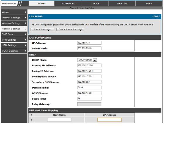
2.1 LAN Configuration
Setup > Network Settings > LAN Configuration
By d efau lt , t h e ro u t er fu n ct io n s as a Dy n amic Ho s t Co n fig u rat io n Pro t o co l (DHCP) s erv er t o t h e h ost s o n t h e W LA N o r LA N n et wo rk. W it h DHCP, PCs an d o t h er LA N d ev ices can b e assig ned IP ad d resses as well as ad d resses fo r DNS s erv ers , W in d o ws In t ern et Name Serv ice (W INS) s erv ers , an d t h e d efau lt g at eway . W it h t h e DHCP s erv er en ab led t h e ro u t er’s IP ad d res s s erv es as t h e g at eway ad d res s fo r LA N an d W LA N clien t s . Th e PCs in t h e LA N are as s ig n ed IP ad d res s es fro m a p o o l o f ad d res ses s pecified in t h is p ro cedu re. Each p o o l ad dress is t ested b efore it is as sig ned t o av o id d u p licat e ad d res s es o n t h e LA N.
Fo r mo s t ap p licat ion s t he d efault DHCP an d TCP/ IP s et t in g s are s at is fact o ry . If y o u wan t an o t h er PC o n y o u r n et wo rk t o b e t h e DHCP s erv er o r if y o u are man u ally
co n fig u rin g |
t h e n et wo rk s et t in g s o f all o f y o u r PCs , s et t h e DHCP mo d e t o ‘n o n e’ . |
|||
DHCP relay |
can b e u s ed t o |
fo rward DHCP leas e in fo rmat io n |
fro m an o t h er LA N |
|
d ev ice |
t h at |
is t h e n et wo rk’s |
DHCP s erv er; t h is is p art icu larly |
u s efu l fo r wireles s |
clien t s . |
|
|
|
|
In s t ead |
o f u s in g a DNS s erv er, y o u can u s e a W in d o ws In t ern et Namin g Serv ice |
|||
(W INS) |
s erv er. A W INS s erv er is t h e eq u iv alen t o f a DNS s erv er b u t u s es t h e |
|||
Net BIOS p ro t o co l t o res o lv e h o s t n ames . Th e ro u t er in clu d es |
t h e W INS s erv er IP |
|||
ad d res s |
in t h e DHCP co n fig u rat io n wh en ackn o wled g in g a DHCP req u es t fro m a |
|||
DHCP clien t . |
|
|
||
Yo u can als o en able DNS p ro xy fo r t h e LA N. W h en t h is is e n abled t he ro u t er t h en as a p ro xy fo r all DNS req u es t s an d co mmu n icat es wit h t h e ISP’s DNS s erv ers . W h en d is ab led all DHCP clien t s receiv e t h e DNS IP ad d res s es o f t h e ISP.

Unified Services Router |
User Manual |
To co n fig u re LA N Co n n ect iv it y , p leas e fo llo w t h e s t ep s b elo w:
1. In the LAN Setup page, enter the following information for your router:
IP ad d res s (fact o ry d efau lt : 192.168.10.1).
If y o u ch an g e t h e IP ad d res s an d click Sav e Set t in g s , t h e GUI will n o t res p o n d . Op en a n ew co n n ect io n t o t h e n ew IP ad d res s an d lo g in ag ain . Be s u re t h e LA N h o s t (t h e mach in e u sed t o man ag e t h e ro u t er) h as o b t ain ed IP ad d res s fro m n ewly as s ig n ed p o o l (o r h as a s t at ic IP ad d res s in t h e ro u t er’s LA N s u b n et ) b efo re acces s in g t h e ro u t er v ia ch an g ed IP ad d res s .
Su b n et mas k (fact o ry d e fau lt : 255.255.255.0).
2. In the DHCP section, select the DHCP mode:
No n e: t h e ro u t er’s DHCP s erv er is d is ab led fo r t h e LA N
DHCP Serv er. W it h t h is o p tio n t h e ro u ter assig ns an IP ad d res s wit h in t h e
s p ecified ran g e p lu s ad d it io n al s p ecified in fo rmat io n t o an y LA N d ev ice
t h at req u es t s DHCP s erv ed ad d res s es .
DHCP Relay : W it h t h is o p t io n en ab led , DHCP clien t s o n t h e LA N can
receiv e IP ad d res s leas es an d co rres p o n d in g in fo rmat io n fro m a DHCP
s erv er o n a d ifferen t s u b n et . Sp ecify t h e Relay Gat eway , an d wh en LA N
clien t s make a DHCP req u es t it will b e p as s ed alo n g t o t h e s erv er
acces s ib le v ia t h e Relay Gat eway IP ad d res s .
If DHCP is b ein g en ab led , en t er t h e fo llo win g DHCP s erv er p aramet ers :
St art in g an d |
En d in g IP A d d res s es : En t er t h e firs t an d las t co n t in u o u s |
||
ad d res ses in t h e IP ad d ress p o ol. A n y n ew DHCP clien t jo in in g t h e LA N is |
|||
as s ig n ed an |
IP ad d res s in |
t h is ran g e . Th e |
d efau lt s t art in g ad d res s is |
192.168.10.2. |
Th e d efau lt |
en d in g ad d res s |
is 192.168.1 0.100. Th es e |
ad d res ses s ho uld b e in t h e s ame IP ad d res s s u b n et as t h e ro u t er’s LA N IP
ad d res s . Yo u may wis h t o s av e p art o f t h e s u b n et ran g e fo r d ev ices wit h
s t at ically as s ig n ed IP ad d res s es in t h e LA N .
Primary an d Seco n d ary DNS s erv ers : If co n fig u red d o main n ame s y s t em
(DNS) s erv ers are av ailab le o n t h e LA N en t er t h eir IP ad d res s es h ere .
W INS Serv er (o p t io n al): En t er t h e IP ad d res s fo r t h e W INS s erv er o r, if p res en t in y o u r n et wo rk, t h e W in d o ws Net Bio s s erv er.
14
Unified Services Router |
User Manual |
Leas e Time: En t er t h e t ime, in h o u rs , fo r wh ich IP ad d res s es are leas ed t o clien t s .
|
|
Relay Gat eway : En t er t h e g at eway add res s . Th is is t h e o n ly co n fig u rat io n |
|
|
|
p aramet er req u ired in t h is s ect io n wh en DHCP Relay |
is s elect ed as it s |
|
|
DHCP mo d e |
|
3. |
In the DNS Host Name Mapping section: |
|
|
|
|
Ho s t Name: Pro v id e a v alid h o s t n ame |
|
|
|
IP ad d res s : Pro v id e t h e IP ad d res s o f t h e h o s t n ame, |
|
4. |
In the LAN proxy section: |
|
|
|
|
En ab le DNS Pro xy : To en ab le t h e ro u t er t o act as a |
p ro xy fo r all DNS |
|
|
req u es ts an d co mmu n icat e wit h t h e ISP’s DNS s erv ers , click t h e ch eckb o x. |
|
5. |
Click Save Settings to apply all changes . |
|
|
Figure 1: Se tup page for LAN TCP/IP s e ttings
15

Unified Services Router User Manual
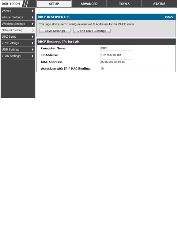
2.1.1 LAN DHCP Reserved IPs
Setup > Network Settings > LAN DHCP Reserved IPs
Th is ro u t er DHCP s erv er can as sig n TCP/ IP co n fig urat io n s t o co mp u t ers in t h e LA N exp licit ly b y ad d in g clien t 's n etwo rk in t erface h ardware ad dress an d t he IP ad d ress t o b e as s ig ned t o t h at clien t in DHCP s erv er's d atabase . W h enever DHCP s erv er receiv es a req u est fro m c lien t , h ard ware ad dress o f t h at clien t is co mp ared wit h t h e h ard ware
ad d res s lis t |
p res en t |
in |
t h e d at ab as e, if an |
IP ad d res s is |
alread y as s ig n ed t o t h at |
co mp u t er o r |
d ev ice |
in |
t h e d at ab as e , t h e |
cu s t o mized |
IP ad d res s is co n fig u red |
o t h erwis e an IP ad d ress is ass ig n ed t o t h e clien t au t o mat ically fro m t h e DHCP p o o l.
Computer Name : Th e u s er d efin ed n ame fo r t h e LA N h o s t .
IP Addres s es : Th e LA N IP ad d res s o f a h o s t t h at is res erv ed b y t h e DHCP s erv er.
MAC Addres s es : Th e M A C ad d res s t h at will b e as s ig n ed t h e res e rv ed IP ad d res s wh en it is o n t h e LA N.
As s ociate with IP/MAC Binding : W h en t h e u s er en ab les t h is o p t io n t h e Co mp u t er Name, IP an d M A C ad d res s es are as s o ciat ed wit h t h e IP/ M A C b in d in g .
Th e act io n s t h at can b e t aken o n lis t o f res erv ed IP ad d res s es are:
S elect: Select s all t h e res erv ed IP ad d res s es in t h e lis t .
Edit: Op en s t h e LA N DHCP Res erv ed IP Co n fig u rat io n p ag e t o ed it t h e s elect ed b in d in g ru le .
Delete : Delet es t h e s elect ed IP ad d res s res erv at io n (s )
Add: Op en s t h e LA N DHCP Res erv ed IP Co n fig u rat io n p ag e t o ad d a n ew b in d in g ru le .
16
Unified Services Router |
User Manual |
Figure 2: LAN DHCP Re s e rve d IPs |
|
2.1.2 LAN DHCP Leased Clients
Setup > Network Settings > LAN DHCP Leased Clients
Th is p ag e p ro v id es t h e lis t o f clien t s co n n ect t o LA N DHCP s erv er.
17

Unified Services Router |
User Manual |
Figure 3: LAN DHCP Le as e d Clie nts |
|
IP Addres s es : Th e LA N IP ad d res s o f a h o s t t h at mat ch es t h e res erv ed IP lis t .
MAC Addres s es : Th e M A C ad d ress o f a LA N h o s t t h at h as a co n figu red IP ad d res s
res erv at io n .
2.1.3 LAN Configuration in an IPv6 Network
Advanced > IPv6 > IPv6 LAN > IPv6 LAN Config
(1) In IPv 6 mo d e, t h e LA N DHCP s erv er is en ab led b y d efau lt (s imilar t o IPv 4 mo d e). Th e DHCPv 6 s erv er will s erv e IPv 6 ad d resses fro m co n fig u red ad d res s p o o ls wit h t h e IPv 6 Prefix Len g t h as s ig n ed t o t h e LA N.
IPv 4 / IPv 6 mo d e mu s t b e en ab led in t h e Advanced > IPv6 > IP mode t o en ab le
IPv 6 co n fig u rat io n o p t io n s .
LAN Settings
Th e d efau lt IPv 6 LA N ad d ress fo r t h e ro u ter is fec0 ::1 . Yo u can ch ang e t h is 128 b it IPv 6 ad d res s b ased o n y o ur n et wo rk req u iremen t s . Th e o t h er field t h at d efin es t h e
LA N s et t in g s |
fo r |
t h e ro u t er is t h e p refix len g t h . Th e IPv 6 |
n et wo rk (s u b n et ) is |
id en t ified b y |
t h e |
in it ial b it s o f t h e ad d res s called t h e p refix. |
By d efau lt t h is is 6 4 |
b it s lo n g . A ll h o s ts in t h e n etwo rk h av e co mmo n in it ial b it s fo r t h eir IPv 6 ad d res s ; t h e n u mb er o f co mmo n in it ial b it s in t h e n et wo rk’s ad d res s es is s et b y t h e p refix len g t h field .
18

Unified Services Router |
User Manual |
Figure 4: IPv6 LAN and DHCPv6 configurat io n
If y o u ch an g e t h e IP ad d res s an d click Sav e Set t in g s , t h e GUI will n o t res p o n d . Op en a n ew co n n ect io n t o t h e n ew IP ad d res s an d lo g in ag ain . Be s u re t h e LA N h o s t (t h e mach in e u sed t o man ag e t h e ro u t er) h as o b t ain ed IP ad d res s fro m n ewly as s ig n ed p o o l (o r h as a s t at ic IP ad d res s in t h e ro u t er’s LA N s u b n et ) b efo re acces s in g t h e ro u t er v ia ch an g ed IP ad d res s .
19

Unified Services Router |
User Manual |
A s wit h an IPv 4 LA N n et wo rk, t h e |
ro u t er h as a DHCPv 6 s erv er. If en ab led , t h e |
ro u t er as s ig n s an IP ad d res s wit h in t h e s p ecified ran g e p lu s ad d it io n al s p ecified in fo rmat io n t o an y LA N PC t h at req u es t s DHCP s erv ed ad d res s es .
Th e fo llo win g s et t in g s are u s ed t o co n fig u re t h e DHCPv 6 s erv er:
DHCP M o d e: Th e IPv 6 DHCP s erv er is eit h er s t at eless o r s t at efu l. If s t ateless is
s elect ed an ext ern al IPv 6 DHCP s erv er is n o t req u ired as t h e IPv 6 LA N h o s t s
are au t o -co nfig ured b y t h is ro u ter. In t h is case t h e ro u ter ad vertis emen t d aemo n
(RA DVD) mu s t b e co n fig u red o n t h is d ev ice an d ICM Pv 6 ro u t er d is co v ery
mes s ag es are u s ed b y t h e h o s t fo r au t o -co n fig u rat io n . Th ere are n o man ag ed
ad d res ses t o s erv e t h e LA N n o d es. If s t at efu l is s elected t h e IPv 6 LA N h o s t will
rely o n an ext ern al DHCPv 6 s erv er t o p ro v id e req u ired co n fig u rat io n s et t in g s
Th e d o main n ame o f t h e DHCPv 6 s erv er is an o p t io n al s et t in g
Serv er Preferen ce is u s ed t o in d icat e t h e p re feren ce lev el o f t h is DHCP s erv er.
DHCP ad v ert is e mes s ag es wit h t h e h ig h es t s erv er p referen ce v alu e t o a LA N
h o s t are p referred o v er o t h er DHCP s erv er ad v ert is e mes s ag es . Th e d efau lt is
255.
Th e DNS s erv er d et ails can b e man u ally en t ered h ere (p rimary / s eco n d ary
o p t io n s . A n alt ern at iv e is t o allo w t h e LA N DHCP clien t t o receiv e t h e DNS
s erv er d et ails fro m t h e ISP d irect ly . By s elect in g Us e DNS p ro xy , t h is ro u t er
act s as a p ro xy fo r all DNS req u es t s an d co mmu n icat es wit h t h e ISP’s DNS
s erv ers (a W A N co n fig u ra t io n p aramet er).
Primary an d Seco n d ary DNS s erv ers : If t h ere is co n fig u red d o main n ame
s y s t em (DNS) s erv ers av ailab le o n t h e LA N en t er t h e IP ad d res s es h ere .
Leas e/ Reb in d t ime s et s t h e d uratio n o f t h e DHCPv 6 leas e fro m t h is ro u t er to the
LA N clien t .
IPv6 Address Pools
Th is feat u re allo ws y o u t o d efin e t h e IPv 6 d eleg at io n p refix fo r a ran g e o f IP ad d res ses t o b e s erv ed b y t h e g at eway ’s DHCPv 6 s erv er . Us in g a d eleg at io n p refix y o u can au t omat e t he p ro cess o f in fo rmin g o t h er n et workin g eq uip men t o n t h e LA N o f DHCP in fo rmat io n s p ecific fo r t h e as s ig n ed p refix.
Prefix Delegation
Th e fo llo win g s et t in g s are u s ed t o co n fig u re t h e Prefix Deleg at io n :
Prefix Deleg at io n : Select t h is o p t io n t o en ab le p refix d eleg at io n in DHCPv 6
s erv er. Th is o p t io n can b e s elect ed o n ly in St at eles s A d d res s A u t o
Co n fig u rat io n mo d e o f DHCPv 6 s erv er.
20

Unified Services Router |
User Manual |
Prefix A d d res s : IPv 6 p refix ad d res s in t h e DHCPv 6 s erv er p refix p o o l
Prefix Len g t h : Len g t h p refix ad d res s
2.1.4Configuring IPv6 Router Advertisements
Ro u t er A d v ertis emen ts are an alo go us t o IPv 4 DHCP as s ig nmen ts fo r LA N clien t s , in t h at t h e ro u t er will as s ig n an IP ad d res s an d s u p p o rt in g n et wo rk in fo rmat io n t o d ev ices t hat are co n fig ured t o accept s uch d etails. Ro u t er A dv ert isemen t is req u ired in an IPv 6 n et wo rk is req u ired fo r s t at eless au to con fig u rat io n o f t h e IPv 6 LA N. By co n fig u rin g t he Ro u ter A d vertisemen t Daemo n o n t h is ro u ter, t h e DSR will lis t en o n t h e LA N fo r ro u t er s o licit at io n s an d res p o n d t o t h es e LA N h o s t s wit h ro u t er ad v is emen t s .
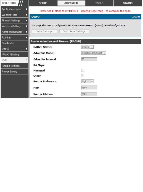
RADVD
Advanced > IPv6 > IPv6 LAN > Router Advertisement
To s u p p ort s tateless IPv 6 au t o co nfig uratio n o n t h e LA N, s et t h e RA DVD s t at u s t o En ab le . Th e fo llo win g s et t in g s are u s ed t o co n fig u re RA DVD:
A d v ert ise M o de: Select Un solicit ed M u lt icast t o send ro ut er ad v ert is emen t s
|
(RA ’s ) |
t o all in t erfaces |
in |
t h e mu lt icas t g ro u p . To res t rict RA ’s t o |
well- |
||
|
kn o wn |
IPv 6 ad d res s es |
o n |
t h e LA N, an d t h ereb y red u ce o v erall n et wo rk |
|||
|
t raffic, s elect Un icas t o n ly . |
|
|
|
|||
|
A d v ert ise In t erv al: W h en ad vert isemen ts are u n s o licit ed mu lt icas t p acket s , |
||||||
|
t h is in t erv al s et s t h e |
maximu m t ime b et ween ad v ert is emen t s fro m t h e |
|||||
|
in t erface . Th e act u al d u rat io n b et ween ad v ert is emen t s is a ran d o m v alu e |
||||||
|
b et ween o n e t h ird o f t h is field an d t h is field . Th e d efau lt is 30 s eco n d s . |
||||||
|
RA Flag s : Th e ro u t er ad vertis emen ts (RA ’s ) can b e s en t wit h o n e o r b o t h o f |
||||||
|
t h es e flag s. Ch o se M an ag ed t o u s e t h e ad min is t ered / s t a t efu l p ro t o co l fo r |
||||||
|
ad d res s |
au t o co n fig u rat io n . If t h e Ot h er flag |
is s elect ed t h e h o s t |
u s es |
|||
|
ad min is t ered / s t at efu l p ro t o co l fo r n o n -ad d res s au t o co n fig u rat io n . |
|
|||||
|
Ro u t er |
Preferen ce : |
t h is |
lo w/ med iu m/ h ig h |
p aramet er d et ermin es |
t h e |
|
|
p referen ce asso ciat ed wit h t h e RA DVD p ro ces s o f t h e ro u t er. Th is is u s efu l |
||||||
|
if t h ere are o t h er RA DVD en ab led d ev ices o n t h e LA N as it h elp s av o id |
||||||
|
co n flict s fo r IPv 6 clien t s . |
|
|
|
|||
|
M TU: Th e ro u t er ad v ert is emen t will s et t h is |
maximu m t ran s mis s io n u n it |
|||||
|
(M TU) v alu e fo r all n o d es in t h e LA N t h at are au t o co n fig ured b y t he ro uter. |
||||||
|
Th e d efau lt is 1500. |
|
|
|
|
|
|
|
Ro u t er Lifet ime : Th is v alu e is p res en t in RA ’s an d in d icat es t h e u s efu ln es s |
||||||
|
o f t h is |
ro u t er as a |
d efau lt |
ro u t er fo r t h e in t erface . Th e d efau lt is |
3600 |
||
21
Unified Services Router |
User Manual |
s eco n ds. Up o n exp irat io n o f t h is v alu e, a n ew RA DVD exch an g e mu s t t ake
p lace b et ween t h e h o s t an d t h is ro u t er.
Figure 5: Configu ri ng the Route r Adve rtis e me nt Dae mon
Advertisement Prefixes
Advanced > IPv6 > IPv6 LAN > Advertisement Prefixes
Th e ro u t er ad v ert isemen ts co nfig ured wit h ad v ert is emen t p refixes allo w t h is ro u t er t o in fo rm h o s t s h o w t o p erfo rm s t at eles s ad d res s au t o co n fig u rat io n . Ro u t er ad v ert is emen ts co n t ain a lis t o f s u b n et p refixes t h at allo w t h e ro u t er t o d et ermin e n eig h b o u rs an d wh et h er t h e h o s t is o n t h e s ame lin k as t h e ro u t er .
Th e fo llo win g p refix o p t io n s are av ailab le fo r t h e ro u t er ad v ert is emen t s :
IPv 6 Prefix Ty p e : To en s u re h o s t s s u p p o rt IPv 6 t o IPv 4 t u n n el s elect t h e
6t o 4 p refix t y p e . Select in g Glo b al/ Lo cal/ ISA TA P will allo w t h e n o d es t o
s u p p o rt all o t h er IPv 6 ro u t in g o p t io n s
SLA ID: Th e SLA ID (Sit e -Lev el A g g reg at io n Id en t ifier) is av ailab le wh en
6t o 4 Prefixes are s elect ed . Th is s h o u ld b e t h e in t erface ID o f t h e ro u t er’s
LA N in t erface u s ed fo r ro u t er ad v ert is emen t s .
22

Unified Services Router |
User Manual |
IPv 6 Prefix: W h en u s ing Glo b al/ Lo cal/ISA TAP p refixes , t h is field is u s ed to
d efin e t h e IPv 6 n et wo rk ad v ert is ed b y t h is ro u t er.
IPv 6 Prefix Len g t h : Th is v alu e in d icat e s t h e n u mb er co n t ig u o u s , h ig h er
o rd er b it s o f t h e IPv 6 ad d res s t h at d efin e u p t h e n et wo rk p o rt io n o f t h e
ad d res s . Ty p ically t h is is 64.
Prefix Lifet ime: Th is d efin es t h e d u rat io n (in s eco n d s ) t h at t h e req u es t in g
n o d e is allo wed t o u s e t h e adv ert is ed p refix. It is an alo g o u s t o DHCP leas e
t ime in an IPv 4 n et wo rk.
Figure 6: IPv6 Adve rtis e me nt Pre fix s e ttings
2.2 VLAN Configuration
Th e ro u t er s u p p o rt s v irt u al n et wo rk is o lat io n o n t h e LA N wit h t h e u s e o f VLA Ns . LA N d ev ices can b e co n fig u red t o co mmu n icat e in a s u b n et wo rk d efin ed b y VLA N id en t ifiers . LA N p o rt s can b e as s ig n ed u n iq u e VLA N IDs s o t h at t raffic t o an d fro m t h at p h y s ical p o rt can b e is o lat ed fro m t h e g en eral LA N. VLA N filt erin g is p art icu larly u s efu l t o limit b ro ad cas t p acket s o f a d ev ice in a larg e n et wo rk
VLA N s u p p ort is d is abled b y d efault in t h e ro u ter. In t h e VLA N Co n fig u rat io n p ag e, en ab le VLA N s u p po rt o n t h e ro u ter a n d t h en p ro ceed t o t he n ext s ectio n t o d efin e t h e v irt u al n et wo rk.
Setup > VLAN Settings > Available VLAN
Th e A v ailab le VLA N p ag e s h o ws a lis t o f co n fig ured VLA Ns b y n ame an d VLA N ID. A VLA N memb ers h ip can b e creat ed b y clickin g t h e A d d b u t t o n b elo w t h e Lis t o f A v ailab le VLA Ns .
A VLA N memb ers h ip en t ry co n s is t s o f a VLA N id en t ifier an d t h e n u merical VLA N ID wh ich is as s ig n ed t o t h e VLA N memb ers h ip . Th e VLA N ID v alu e can b e an y
23

Unified Services Router User Manual
n u mb er fro m 2 t o 4091. VLA N ID 1 is res erv ed fo r t h e d efau lt VLA N, wh ich is u s e d fo r u n t ag ged frames receiv ed o n t h e in t erface. By en ab lin g In t er VLA N Ro u t in g , y o u will allo w t raffic fro m LA N h o s ts b elo ng ing t o t his VLA N ID t o p as s t h roug h t o o ther co n fig u red VLA N IDs t h at h av e In t er VLA N Ro u t in g en ab led .
Figure 7: Adding VLAN me mbe rs hips to the LAN
2.2.1 Associating VLANs to ports
In o rd er t o t ag all t raffic t h ro u g h a s p ecific LA N p o rt wit h a VLA N ID, y o u can as s o ciat e a VLA N t o a p h y s ical p o rt .
Setup > VLAN Settings > Port VLAN
VLA N memb ers h ip p ro p ert ies fo r t h e LA N an d wireles s LA N are lis t ed o n t h is page. Th e VLA N Po rt t ab le d is p lay s t he p o rt id en tifier, t h e mo d e s ett ing fo r t h at p o rt an d VLA N memb ers h ip in fo rmat io n . Th e co n fig u rat io n p ag e is acces s ed b y s elect in g o n e o f t h e fo u r p h y s ical p o rt s o r a co n fig u r ed acces s p o in t an d clickin g Ed it .
Th e ed it p ag e o ffers t h e fo llo win g co n fig u rat io n o p t io n s :
M o d e: Th e mo d e o f t h is VLA N can b e Gen eral, A cces s , o r T ru n k. Th e
d efau lt is acces s .
In Gen eral mo d e t h e p o rt is a memb er o f a u s er s elect ab le s et o f VLA Ns .
Th e p o rt s en ds an d receiv es d at a t h at is t ag g ed o r u n t ag g ed wit h a VLA N
ID. If t h e d at a in t o t h e p ort is u n tagged, it is as sig n ed t h e d efin ed PVID. In
t h e co n fig u rat io n fro m Fig u re 4, Po rt 3 is a Gen eral p o rt wit h PVID 3, s o
u n t ag ged d at a in t o Po rt 3 will b e as s ig ned PVID 3. A ll t ag g ed d ata s ent o u t
o f t h e p o rt wit h t h e s ame PVID will b e u n t ag ged. Th is is mo d e is t y p ically
u s ed wit h IP Ph o n es t h at h ave d ual Et h ern et p o rts. Dat a co min g fro m p h o ne
t o t h e s wit ch p o rt o n t h e ro u t er will b e t ag g ed . Dat a p as s in g t h ro u g h t h e
p h o n e fro m a co n n ect ed d ev ice will b e u n t ag g ed .
24

Unified Services Router User Manual
Figure 8: Port VLAN lis t
|
In A cces s mo d e t h e p o rt is a memb er o f a s in g le VLA N (an d o n ly o n e). A ll |
||||||||
|
d at a g o in g in t o an d o u t o f t h e p o rt is u n t ag g ed . Traffic t h ro u g h a p o rt in |
||||||||
|
acces s mo d e lo o ks like an y o t h er Et h ern et frame . |
|
|
|
|||||
|
In Tru n k mo d e t h e p o rt is a memb er o f a u s er s elect ab le s et o f VLA Ns . A ll |
||||||||
|
d at a g o in g in t o an d o u t o f t h e p o rt is t ag ged. Un t agged co min g in t o t he p o rt |
||||||||
|
is n o t fo rward ed , excep t fo r t h e |
d efau lt VLA N wit h PVID=1, wh ich is |
|||||||
|
u n t ag ged. Tru n k p o rt s mu lt ip lex t raffic fo r mu lt ip le VLA Ns o v er t h e s ame |
||||||||
|
p h y s ical lin k. |
|
|
|
|
|
|
|
|
|
Select PVID fo r t h e p o rt wh en t h e Gen eral mo d e is s elect ed . |
|
|
||||||
|
Co n fig u red |
VLA N |
memb ers h ip s |
will b e |
d is p lay ed |
o n |
t h e |
VLA N |
|
|
M emb ers h ip |
Co n fig u rat io n |
fo r t h e p o rt . By |
s elect in g |
o n e |
mo re |
VLA N |
||
|
memb ers h ip |
o p t io n s |
fo r a |
Gen eral o r Tru n k p o rt , t raffic can b e |
ro u t ed |
||||
b et ween t h e s elect ed VLA N memb ers h ip IDs
25
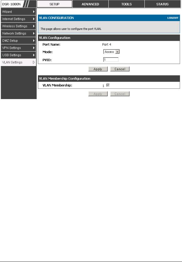
Unified Services Router |
User Manual |
Figure 9: Configu ri ng |
VLAN me mbe rs hip for a port |
2.2.2 Multiple VLAN Subnets
Setup > VLAN Settings > Multi VLAN Settings
Th is p ag e s ho ws a lis t o f av ailab le mu lt i-VLA N s u b n ets . Each co n fig u red VLA N ID can map d irect ly t o a s u b n et wit h in t h e LA N. Each LA N p o rt can b e as s ig n ed a u n iq u e IP ad d ress an d a VLA N s p ecific DHCP s erv er can b e co nfig ured t o ass ig n IP ad d res s leas es t o d ev ices o n t h is VLA N.
VLAN ID: Th e PVID o f t h e VLA N t h at will h av e all memb er d ev ices b e p art o f t h e s ame s u b n et ran g e .
IP Addres s : Th e IP ad d res s as s o ciat ed wit h a p o rt as s ig n ed t h is VLA N ID.
S ubnet Mas k : Su b n et M as k fo r t h e ab o v e IP A d d res s
26
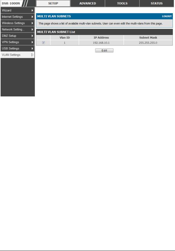
Unified Services Router |
User Manual |
Figure 10: M ultiple |
VLAN Subne ts |
2.2.3 VLAN configuration
Setup > VLAN Settings > VLANconfiguration
Th is p ag e allo ws en ab lin g o r d is ab lin g t h e VLA N fu n ct io n o n t h e ro u t er. Virt u al LA Ns can b e creat ed in t h is ro ut er t o p ro vid e seg men t at io n cap ab ilit ies fo r firewall ru les an d VPN p o licies . Th e LA N n et wo rk is co n s id ered t h e d efau lt VLA N. Ch eck t h e En ab le VLA N b o x t o ad d VLA N fu n ct io n alit y t o t h e LA N.
27

Unified Services Router |
User Manual |
Figure 11: VLAN Configu rat ion
2.3 Configurable Port: DMZ Setup
DSR-150/ 150N/ 250/ 250N d o es n o t h av e a co n fig u rab le p o rt – t h ere is n o DM Z s u p p o rt .
Th is ro u t er s up port s o ne o f t h e p hy sical p o rt s t o b e co n fig u red as a s eco n d ary W A N Et h ern et p o rt o r a d ed icated DM Z p o rt . A DM Z is a s u b n et wo rk t h at is o p en t o t h e p u b lic b u t b eh ind t h e firewall. Th e DM Z ad d s an ad d it io n al lay er o f s ecu rit y t o t h e LA N, as s p ecific s erv ices/p ort s t h at are exp o s ed t o t h e in t ern et o n t h e DM Z d o n o t h av e t o b e exp o s ed o n t he LA N. It is reco mmen d ed t h at h osts t h at mu s t b e exp o sed t o t h e in t ern et (s u ch as web o r email s erv ers ) b e p laced in t h e DM Z n et wo rk. Firewall ru les can b e allo wed t o p ermit acces s s p ecific s erv ices / p o rt s t o t h e DM Z fro m b o t h t h e LA N o r W A N. In t h e ev en t o f an at t ack t o an y o f t h e DM Z n o d es , t h e LA N is n o t n eces s arily v u ln erab le as well.
Setup > DMZ Setup > DMZ Setup Configuration
DM Z co n fig u ratio n is id en tical t o t h e LA N co n fig u ratio n. Th ere are n o rest rictio ns on t h e IP ad d res s o r s u bnet as sign ed t o t h e DM Z p o rt , o t h er t h an t h e fact t h at it can n o t b e id en t ical t o t h e IP ad d res s g iv en t o t h e LA N in t erface o f t h is g at eway .
28
 Loading...